2009 INFINITI QX56 service indicator
[x] Cancel search: service indicatorPage 3155 of 4171

REAR SUSPENSION ASSEMBLYRSU-7
< ON-VEHICLE MAINTENANCE >
C
DF
G H
I
J
K L
M A
B
RSU
N
O P
If vehicle height is not within ± 10 mm (0.39 in) of the specification, perform the control unit initialization
procedure. Refer to SCS-7, "CONSULT-III Function"
.
GENERAL INFORMATION AND RECOMMENDATIONS
1. A Four-Wheel Thrust Alignment should be performed.
This type of alignment is re commended for any NISSAN vehicle.
The four-wheel “thrust” process helps ensure that the vehicle is properly aligned and the steering wheel
is centered.
The alignment machine itself should be ca pable of accepting any NISSAN vehicle.
The alignment machine should be checked to ensure that it is level.
2. Make sure the alignment machine is properly calibrated. Your alignment machine should be regularly calibrated in order to give correct information.
Check with the manufacturer of your specific a lignment machine for their recommended Service/Cali-
bration Schedule.
THE ALIGNMENT PROCESS
IMPORTANT: Use only the alignment specifications listed in this Service Manual. Refer to RSU-29, "Wheel
Alignment (Unladen*1)".
1. When displaying the alignment settings, many alignm ent machines use “indicators”: (Green/red, plus or
minus, Go/No Go). Do NOT use these indicators.
The alignment specifications programmed into your alignment machine that operate these indicators
may not be correct.
This may result in an ERROR.
2. Some newer alignment machines are equipped with an optional “Rolling Compensation” method to “com- pensate” the sensors (alignment targets or head units). Do NOT use this “Rolling Compensation”
method.
Use the “Jacking Compensation” method. After installing the alignment targets or head units, raise the vehicle and rotate the wheels 1/2 turn both ways.
See Instructions in the alignment machine you are using for more information.
CAMBER
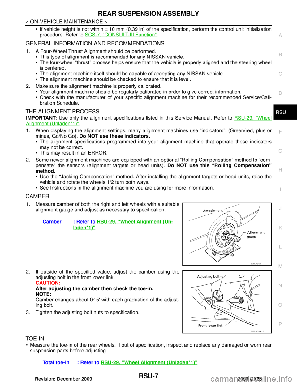
1. Measure camber of both the right and left wheels with a suitable alignment gauge and adjust as necessary to specification.
2. If outside of the specified val ue, adjust the camber using the
adjusting bolt in the front lower link.
CAUTION:
After adjusting the camber then check the toe-in.
NOTE:
Camber changes about 0 ° 5' with each graduation of the adjust-
ing bolt.
3. Tighten the adjusting bolt nuts to specification.
TOE-IN
Measure the toe-in of the rear wheels. If out of s pecification, inspect and replace any damaged or worn rear
suspension parts before adjusting. Camber : Refer to
RSU-29, "Wheel Alignment (Un-
laden*1)"
SRA096A
LEIA0041E
Total toe-in : Refer to RSU-29, "Wheel Alignment (Unladen*1)"
Revision: December 20092009 QX56
Page 3416 of 4171
![INFINITI QX56 2009 Factory Service Manual SEC-106
< SYMPTOM DIAGNOSIS >[WITH INTELLIGENT KEY SYSTEM]
INFINITI VEHICLE IMMOBILI
ZER SYSTEM-NATS SYMPTOMS
INFINITI VEHICLE IMMOBILIZER SYSTEM-NATS SYMPTOMS
Symptom TableINFOID:0000000003775946
NOT INFINITI QX56 2009 Factory Service Manual SEC-106
< SYMPTOM DIAGNOSIS >[WITH INTELLIGENT KEY SYSTEM]
INFINITI VEHICLE IMMOBILI
ZER SYSTEM-NATS SYMPTOMS
INFINITI VEHICLE IMMOBILIZER SYSTEM-NATS SYMPTOMS
Symptom TableINFOID:0000000003775946
NOT](/manual-img/42/57031/w960_57031-3415.png)
SEC-106
< SYMPTOM DIAGNOSIS >[WITH INTELLIGENT KEY SYSTEM]
INFINITI VEHICLE IMMOBILI
ZER SYSTEM-NATS SYMPTOMS
INFINITI VEHICLE IMMOBILIZER SYSTEM-NATS SYMPTOMS
Symptom TableINFOID:0000000003775946
NOTE:
• Before performing the diagnosis in the following table, check “ SEC-3, "
Work Flow"”.
• Check that vehicle is under the condition shown in “Conditions of vehicle” before starting diagnosis, and
check each symptom.
• If the following symptoms are detected, check syst ems shown in the “Diagnosis/service procedure” column
in this order.
CONDITIONS OF VEHICLE (OPERATING CONDITIONS)
• Mechanical key is not inserted into key cylinder.
• Ignition knob switch is not depressed.
Symptom Diagnosis/service procedure Reference page
Security indicator does not turn ON or flash. 1. Check vehicle security indicator
SEC-47
2. Check Intermittent Incident GI-38
Revision: December 20092009 QX56
Page 3452 of 4171

SN-30
< ECU DIAGNOSIS >
SONAR CONTROL UNIT FOR REAR SONAR SYSTEM
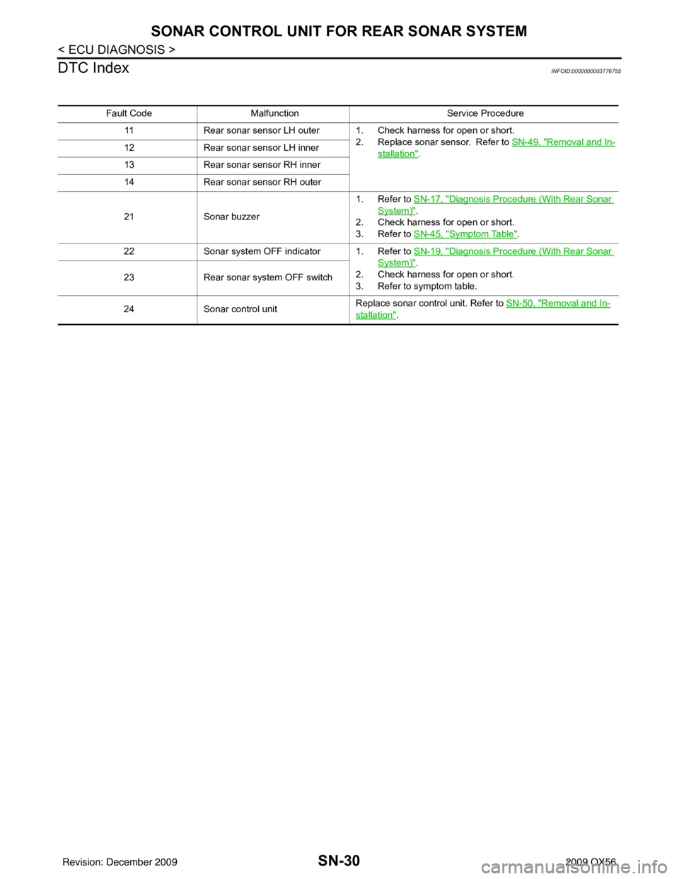
DTC Index
INFOID:0000000003776755
Fault Code Malfunction Service Procedure
11 Rear sonar sensor LH outer 1. Check harness for open or short.
2. Replace sonar sensor. Refer to SN-49, "
Removal and In-
stallation".
12
Rear sonar sensor LH inner
13 Rear sonar sensor RH inner
14 Rear sonar sensor RH outer
21 Sonar buzzer 1. Refer to SN-17, "
Diagnosis Procedure (With Rear Sonar
System)".
2. Check harness for open or short.
3. Refer to SN-45, "
Symptom Table".
22 Sonar system OFF indicator 1. Refer to SN-19, "
Diagnosis Procedure (With Rear Sonar
System)".
2. Check harness for open or short.
3. Refer to symptom table.
23
Rear sonar system OFF switch
24 Sonar control unit Replace sonar control unit. Refer to
SN-50, "
Removal and In-
stallation".
Revision: December 20092009 QX56
Page 3824 of 4171

TM-176
< PRECAUTION >
PRECAUTIONS
All parts should be carefully cleaned with a general purpose, non-flammable solvent before inspection orreassembly.
Gaskets, seals and O-rings should be replaced any time the transmission is disassembled.
It is very important to perform functional tests whenever they are indicated.
The valve body contains precision parts and requires extreme care when parts are removed and serviced. Place disassembled valve body parts in order for easier and proper assembly. Care will also prevent springs
and small parts from becoming scattered or lost.
Properly installed valves, sleeves, plugs, etc. will s lide along bores in valve body under their own weight.
Before assembly, apply a coat of recommended ATF to all parts. Apply petroleum jelly to protect O-rings and
seals, or hold bearings and washers in place during assembly. Do not use grease.
Extreme care should be taken to avoid damage to O-rings, seals and gaskets when assembling.
Clean or replace ATF cooler if excessive foreign material is found in oil pan or clogging strainer. Refer to TM-
183, "A/T Fluid Cooler Cleaning".
After overhaul, refill the transmission with new ATF.
When the A/T drain plug is removed, only some of the fluid is drained. Old A/T fluid will remain in torque con- verter and ATF cooling system.
Always follow the procedures under “Changing A/T Fluid” in the AT section when changing A/T fluid. Refer to
TM-181, "Changing the A/T Fluid (ATF)"
.
Service Notice or PrecautionINFOID:0000000003772016
ATF COOLER SERVICE
If A/T fluid contains fictional material (clutches, bands, etc.), or if an A/T is repaired, overhauled, or replaced,
inspect and clean the A/T fluid cooler mounted in the radiat or or replace the radiator. Flush cooler lines with
cleaning solvent and compressed air after repair. For A/T fluid cooler cleaning procedure, refer to TM-183,
"A/T Fluid Cooler Cleaning". For radiator replacement, refer to CO-15, "Removal and Installation".
CHECKING AND CHANGING A/T FLUID
Increase ATF oil temperature to 80 °C (176 °F) first, then check and adjust oil level at 65 °C (149 °F).
NOTE:
The A/T has both water cooling and air cooling systems . The air cooling system has a bypass valve. When
ATF oil temperature is at or below 50 °C (122 °F), it does not flow through the air cooled system. If A/T oil
level is adjusted without flow throughout the entir e system, the level will be 10mm lower than required.
Therefore, all piping should be filled with oil when adjusting level.
OBD-II SELF-DIAGNOSIS
A/T self-diagnosis is performed by the TCM in combination with the ECM. Refer to the table on TM-32,
"CONSULT-III Function (TRANSMISSION)" for the indicator used to display each self-diagnostic result.
The self-diagnostic results indicated by the MIL ar e automatically stored in both the ECM and TCM memo-
ries.
Always perform the procedure on TM-30, "OBD-II Diagnostic Trouble Code (DTC)"
to complete the
repair and avoid unnecessary blinking of the MIL.
For details of OBD-II, refer to TM-30
.
Certain systems and components, especially those related to OBD, may use the new style slide-
locking type harness connector. For descrip tion and how to disconnect, refer to PG-68
.
Revision: December 20092009 QX56
Page 3866 of 4171

TM-218
< REMOVAL AND INSTALLATION >
TRANSMISSION ASSEMBLY
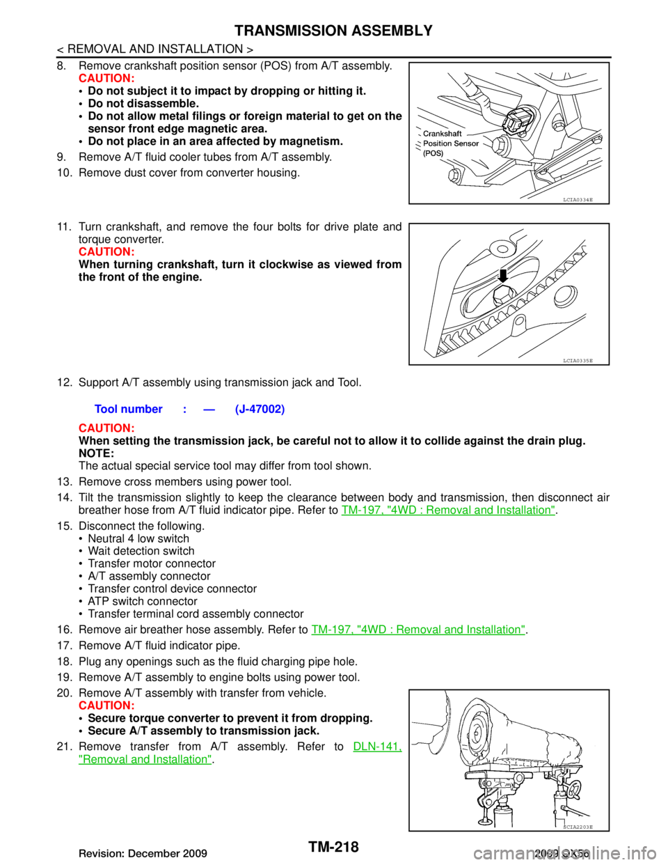
8. Remove crankshaft position sensor (POS) from A/T assembly.CAUTION:
Do not subject it to impact by dropping or hitting it.
Do not disassemble.
Do not allow metal filings or fo reign material to get on the
sensor front edge magnetic area.
Do not place in an area affected by magnetism.
9. Remove A/T fluid cooler tubes from A/T assembly.
10. Remove dust cover from converter housing.
11. Turn crankshaft, and remove the four bolts for drive plate and torque converter.
CAUTION:
When turning crankshaft, turn it clockwise as viewed from
the front of the engine.
12. Support A/T assembly using transmission jack and Tool. CAUTION:
When setting the transmission jack, be careful not to allow it to collide against the drain plug.
NOTE:
The actual special service tool may differ from tool shown.
13. Remove cross members using power tool.
14. Tilt the transmission slightly to keep the cl earance between body and transmission, then disconnect air
breather hose from A/T fluid indicator pipe. Refer to TM-197, "4WD : Removal and Installation"
.
15. Disconnect the following. Neutral 4 low switch
Wait detection switch
Transfer motor connector
A/T assembly connector
Transfer control device connector
ATP switch connector
Transfer terminal cord assembly connector
16. Remove air breather hose assembly. Refer to TM-197, "4WD : Removal and Installation"
.
17. Remove A/T fluid indicator pipe.
18. Plug any openings such as the fluid charging pipe hole.
19. Remove A/T assembly to engine bolts using power tool.
20. Remove A/T assembly with transfer from vehicle. CAUTION:
Secure torque converter to prevent it from dropping.
Secure A/T assembly to transmission jack.
21. Remove transfer from A/T assembly. Refer to DLN-141,
"Removal and Installation".
LCIA0334E
LCIA0335E
Tool number : — (J-47002)
SCIA2203E
Revision: December 20092009 QX56