2009 INFINITI QX56 diagram
[x] Cancel search: diagramPage 3745 of 4171
A/T SHIFT LOCK SYSTEMTM-97
< COMPONENT DIAGNOSIS >
CEF
G H
I
J
K L
M A
B
TM
N
O P
A/T SHIFT LOCK SYSTEM
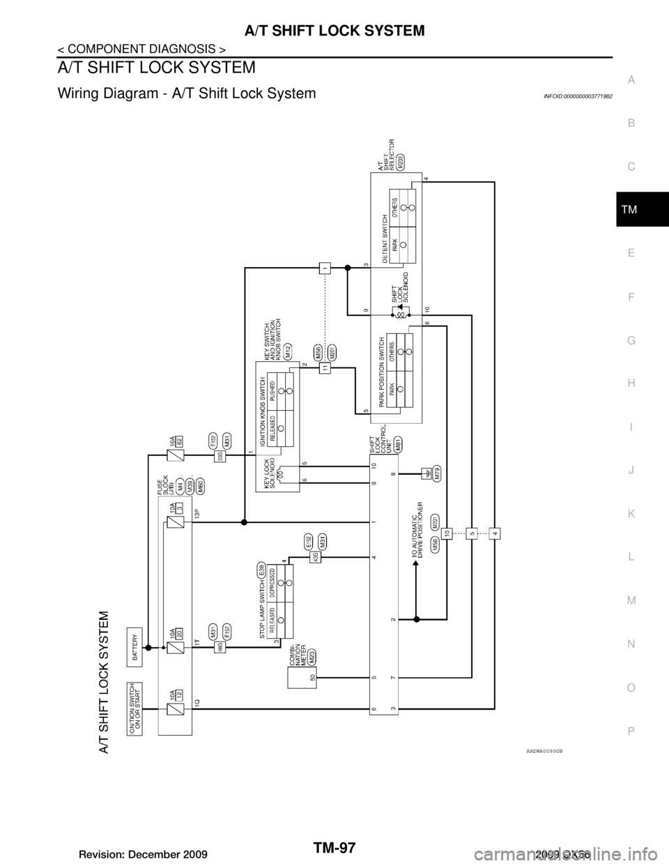
Wiring Diagram - A/ T Shift Lock SystemINFOID:0000000003771982
AADWA0090GB
Revision: December 20092009 QX56
Page 3754 of 4171
TM-106
< ECU DIAGNOSIS >
TCM
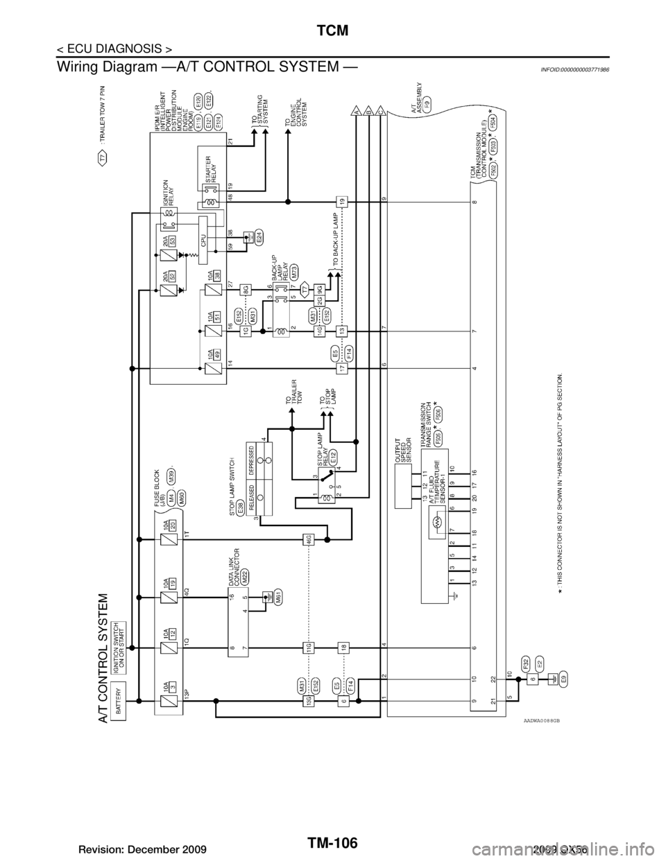
Wiring Diagram —A/T CONTROL SYSTEM —
INFOID:0000000003771986
AADWA0088GB
Revision: December 20092009 QX56
Page 3957 of 4171
HEATER & COOLING UNIT ASSEMBLYVTL-17
< ON-VEHICLE REPAIR >
C
DE
F
G H
J
K L
M A
B
VTL
N
O P
Removal
1. Move the two front seats to the rear most position on the seat track.
2. Disconnect the battery negative terminal and battery positive terminal.
3. Discharge the refrigerant from the A/C system. Refer to
HA-20, "
HFC-134a (R-134a) Service Procedure".
4. Drain the coolant from the engine cooling system. Refer to CO-11, "
Changing Engine Coolant".
5. Disconnect the front heater hoses from the front heater core.
6. Disconnect the high/low pressure pipes from the front expansion valve.
7. Remove the instrument panel and console panel. Refer to IP-13, "
Removal and Installation".
8. Disconnect the instrument panel wire harness at t he RH and LH in-line connector brackets, and the fuse
block (J/B) electrical connectors. Refer to PG-9, "
Wiring Diagram — Battery Power Supply —".
9. Disconnect the steering member from each side of the vehicle body.
10. Remove the front heater and cooling unit assembly with it attached to the steering member, from the vehi- cle.
CAUTION:
Use care not to damage the seats and interior trim panels when removing the front heater and
cooling unit assembly with it at tached to the steering member.
11. Remove the front heater and cooling uni t assembly from the steering member.
Installation
Installation is in the reverse order of removal.
CAUTION:
• Replace the O-ring of the low-pressure pipe and high-pressure pipe with a new one, and apply com-
pressor oil to it when installing it.
• After charging the refrigerant, check for leaks.
NOTE:
• Fill the engine cooling system with the specified coolant mixture. Refer to CO-11, "
Changing Engine Cool-
ant".
• Recharge the A/C system. Refer to HA-20, "
HFC-134a (R-134a) Service Procedure".
REAR HEATER AND COOLING UNIT ASSEMBLY
Removal
1. Discharge the refrigerant from the A/C system. Refer to HA-20, "HFC-134a (R-134a) Service Procedure".
2. Drain the coolant from the engine cooling system. Refer to CO-11, "
Changing Engine Coolant".
3. Remove the luggage side finisher lower and upper RH. Refer to INT-19, "
Removal and Installation".
4. Disconnect the rear heater core hoses from the rear heater core.
5. Disconnect the rear A/C pipes from the rear expansion valve.
6. Disconnect the following electrical connectors: • Rear blower motor
• Rear variable blower control
• Rear air mix door motor
• Rear mode door motor
7. Disconnect the ducts and drain tube from the rear heater and cooling unit assembly.
8. Remove the rear heater and cooling unit assembly.
Installation
Installation is in the reverse order of removal.
CAUTION:
• Replace the O-ring of the low-pressure pipe and high-pressure pipe with a new one, and apply com- pressor oil to it when installing it.
• After charging the refrigerant, check for leaks.
NOTE:
• Fill the engine cooling system with the specified coolant mixture. Refer to CO-11, "
Changing Engine Cool-
ant".
• Recharge the A/C system. Refer to HA-20, "
HFC-134a (R-134a) Service Procedure".
Revision: December 20092009 QX56
Page 3978 of 4171
WCS
WCS-1
DRIVER INFORMATION & MULTIMEDIA
C
DE
F
G H
I
J
K L
M B
SECTION WCS
A
O P
CONTENTS
WARNING CHIME SYSTEM
BASIC INSPECTION ....... .............................3
DIAGNOSIS AND REPAIR WORKFLOW ..... .....3
Work Flow ........................................................... ......3
FUNCTION DIAGNOSIS ...............................4
WARNING CHIME SYSTEM .......................... .....4
WARNING CHIME SYSTEM .......................................4
WARNING CHIME SYSTEM : System Diagram . ......4
WARNING CHIME SYSTEM : System Description
......
4
WARNING CHIME SYSTEM : Component Parts
Location ............................................................... ......
5
WARNING CHIME SYSTEM : Component De-
scription .....................................................................
5
LIGHT REMINDER WARNING CHIME ................. ......6
LIGHT REMINDER WARNING CHIME : System
Diagram .....................................................................
6
LIGHT REMINDER WARNING CHIME : System
Description ................................................................
6
LIGHT REMINDER WARNING CHIME : Compo-
nent Parts Location ...................................................
7
LIGHT REMINDER WARNING CHIME : Compo-
nent Description ........................................................
7
SEAT BELT WARNING CHIME ............................ ......7
SEAT BELT WARNING CHIME : System Diagram
......
8
SEAT BELT WARNING CHIME : System Descrip-
tion ...................................................................... ......
8
SEAT BELT WARNING CHIME : Component
Parts Location ...........................................................
9
SEAT BELT WARNING CHIME : Component De-
scription .....................................................................
9
KEY WARNING CHIME ......................................... ....10
KEY WARNING CHIME : System Diagram ............10
KEY WARNING CHIME : System Description ........10
KEY WARNING CHIME : Component Parts Loca-
tion ....................................................................... ....
11
KEY WARNING CHIME : Component Description ....11
DIAGNOSIS SYSTEM (METER) .......................12
CONSULT-III Function (METER/M&A) ....................12
DIAGNOSIS SYSTEM (BCM) ...........................14
BUZZER ................................................................. ....14
BUZZER : CONSULT-III Function (BCM - BUZZ-
ER) ..........................................................................
14
COMPONENT DIAGNOSIS .........................15
POWER SUPPLY AND GROUND CIRCUIT ....15
COMBINATION METER ........................................ ....15
COMBINATION METER : Diagnosis Procedure .....15
COMBINATION METER : Diagnosis Procedure .....16
BCM (BODY CONTROL MODULE) ...................... ....16
BCM (BODY CONTROL MODULE) : Diagnosis
Procedure ............................................................ ....
16
METER BUZZER CIRCUIT ...............................18
Description ...............................................................18
Component Function Check ....................................18
Diagnosis Procedure ..............................................18
SEAT BELT BUCKLE SWITCH SIGNAL CIR-
CUIT ..................................................................
19
Description ...............................................................19
Component Function Check ..................................19
Diagnosis Procedure ..............................................19
Component Inspection .............................................20
KEY SWITCH SIGNAL CIRCUIT ......................21
Description ...............................................................21
Component Function Check ..................................21
Diagnosis Procedure ..............................................21
Component Inspection .............................................22
Revision: December 20092009 QX56
Page 3979 of 4171

WCS-2
WARNING CHIME SYSTEM .............................23
Wiring Diagram .................................................... ...23
ECU DIAGNOSIS ..................................... ...28
COMBINATION METER ................................. ...28
Reference Value .................................................. ...28
Wiring Diagram .......................................................30
Fail Safe .................................................................46
DTC Index ..............................................................47
BCM (BODY CONTROL MODULE) ..................49
Reference Value .................................................. ...49
Terminal Layout ......................................................51
Physical Values ......................................................51
Wiring Diagram .......................................................57
SYMPTOM DIAGNOSIS .............................62
THE LIGHT REMINDER WARNING DOES
NOT SOUND ................................................... ...
62
Description ........................................................... ...62
Diagnosis Procedure ...............................................62
THE SEAT BELT WARNING CONTINUES
SOUNDING, OR DOES NOT SOUND ...............
63
Description ........................................................... ...63
Diagnosis Procedure ...............................................63
THE KEY WARNING DOES NOT SOUND .......64
Description ........................................................... ...64
Diagnosis Procedure ...............................................64
PRECAUTION ............................................65
PRECAUTIONS .............................................. ...65
Precaution for Supplemental Restraint System
(SRS) "AIR BAG" and "SEAT BELT PRE-TEN-
SIONER" .............................................................. ...
65
Revision: December 20092009 QX56
Page 3981 of 4171
WCS-4
< FUNCTION DIAGNOSIS >
WARNING CHIME SYSTEM
FUNCTION DIAGNOSIS
WARNING CHIME SYSTEM
WARNING CHIME SYSTEM
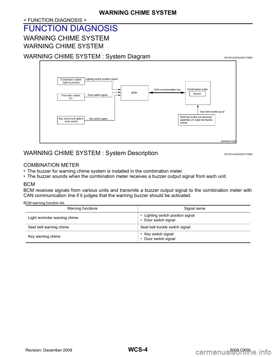
WARNING CHIME SYSTEM : System DiagramINFOID:0000000003776688
WARNING CHIME SYSTEM : System DescriptionINFOID:0000000003776689
COMBINATION METER
• The buzzer for warning chime system is installed in the combination meter.
• The buzzer sounds when the combination meter receives a buzzer output signal from each unit.
BCM
BCM receives signals from various units and transmits a buzzer output signal to the combination meter with
CAN communication line if it judges that the warning buzzer should be activated.
BCM warning function list
AWNIA0210GB
Warning functions Signal name
Light reminder warning chime • Lighting switch position signal
• Door switch signal
Seat belt warning chime Seat belt buckle switch signal
Key warning chime • Key switch signal
• Door switch signal
Revision: December 20092009 QX56
Page 3983 of 4171
WCS-6
< FUNCTION DIAGNOSIS >
WARNING CHIME SYSTEM
LIGHT REMINDER WARNING CHIME
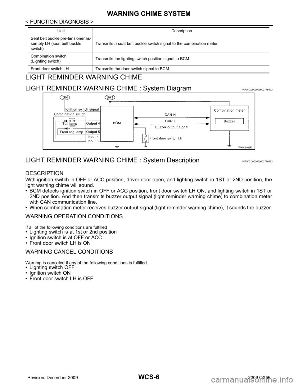
LIGHT REMINDER WARNING CHIME : System DiagramINFOID:0000000003776692
LIGHT REMINDER WARNING CHIME : System DescriptionINFOID:0000000003776693
DESCRIPTION
With ignition switch in OFF or ACC position, driver door open, and lighting switch in 1ST or 2ND position, the
light warning chime will sound.
• BCM detects ignition switch in OFF or ACC position, front door switch LH ON, and lighting switch in 1ST or2ND position. And then transmits buzzer output signal (light reminder warning chime) to combination meter
with CAN communication line.
• When combination meter receives buzzer output signal ( light reminder warning chime), it sounds the buzzer.
WARNING OPERATION CONDITIONS
If all of the following conditions are fulfilled• Lighting switch is at 1st or 2nd position
• Ignition switch is at OFF or ACC
• Front door switch LH is ON
WARNING CANCEL CONDITIONS
Warning is canceled if any of the following conditions is fulfilled.
• Lighting switch OFF
• Ignition switch ON
• Front door switch LH is OFF
Seat belt buckle pre-tensioner as-
sembly LH (seat belt buckle
switch)Transmits a seat belt buckle switch signal to the combination meter.
Combination switch
(Lighting switch) Transmits the lighting switch position signal to BCM.
Front door switch LH Transmits the door switch signal to BCM.
Unit
Description
WKIA5465E
Revision: December 20092009 QX56
Page 3985 of 4171
WCS-8
< FUNCTION DIAGNOSIS >
WARNING CHIME SYSTEM
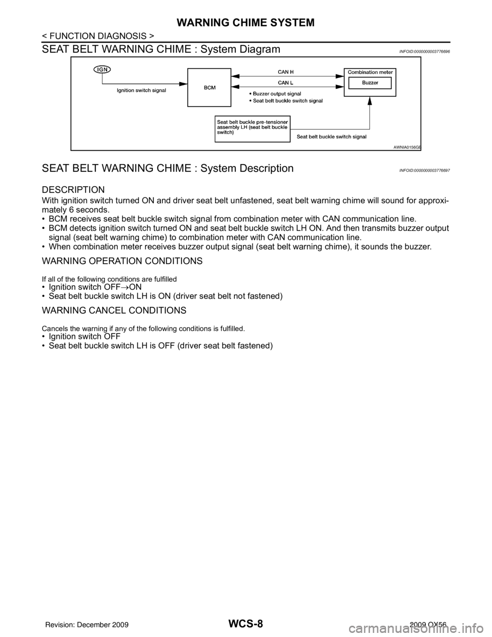
SEAT BELT WARNING CHIME : System Diagram
INFOID:0000000003776696
SEAT BELT WARNING CHIME : System DescriptionINFOID:0000000003776697
DESCRIPTION
With ignition switch turned ON and driver seat belt unfastened, seat belt warning chime will sound for approxi-
mately 6 seconds.
• BCM receives seat belt buckle switch signal from combination meter with CAN communication line.
• BCM detects ignition switch turned ON and seat belt buckle switch LH ON. And then transmits buzzer output signal (seat belt warning chime) to combination meter with CAN communication line.
• When combination meter receives buzzer output signal (seat belt warning chime), it sounds the buzzer.
WARNING OPERATION CONDITIONS
If all of the following conditions are fulfilled• Ignition switch OFF→ON
• Seat belt buckle switch LH is ON (driver seat belt not fastened)
WARNING CANCEL CONDITIONS
Cancels the warning if any of the following conditions is fulfilled.
• Ignition switch OFF
• Seat belt buckle switch LH is OFF (driver seat belt fastened)
AWNIA0156GB
Revision: December 20092009 QX56