Page 3987 of 4171
WCS-10
< FUNCTION DIAGNOSIS >
WARNING CHIME SYSTEM
KEY WARNING CHIME
KEY WARNING CHIME : System DiagramINFOID:0000000003776700
KEY WARNING CHIME : System DescriptionINFOID:0000000003776701
WHEN MECHANICAL KEY IS USED
With the key inserted into the key switch, and the ignition switch in the LOCK or ACC position, when driver's
door is opened, the warning chime will sound.
• BCM detects key inserted into the ignition switch, and sends key warning signal to combination meter with CAN communication line.
• When combination meter receives key warning signal, it sounds the warning chime.
WHEN INTELLIGENT KEY IS CARRIED WITH THE DRIVER
Refer to DLK-6, "Work Flow".
WKIA5464E
Revision: December 20092009 QX56
Page 4000 of 4171
WCS
WARNING CHIME SYSTEMWCS-23
< COMPONENT DIAGNOSIS >
C
DE
F
G H
I
J
K L
M B A
O P
WARNING CHIME SYSTEM
Wiring DiagramINFOID:0000000003776719
ABNWA0073GB
Revision: December 20092009 QX56
Page 4007 of 4171
WCS-30
< ECU DIAGNOSIS >
COMBINATION METER
Wiring Diagram
INFOID:0000000004115461
AANWA0124GB
Revision: December 20092009 QX56
Page 4034 of 4171
WCS
BCM (BODY CONTROL MODULE)WCS-57
< ECU DIAGNOSIS >
C
DE
F
G H
I
J
K L
M B A
O P
Wiring DiagramINFOID:0000000004115467
AAMWA0236GB
Revision: December 20092009 QX56
Page 4043 of 4171

WT-1
SUSPENSION
C
DF
G H
I
J
K L
M
SECTION WT
A
B
WT
N
O PCONTENTS
ROAD WHEELS & TIRES
BASIC INSPECTION ....... .............................3
DIAGNOSIS AND REPAIR WORKFLOW ..... .....3
Repair Work Flow ................................................ ......3
INSPECTION AND ADJUSTMENT .....................5
Preliminary Check ............................................... ......5
Transmitter Wake Up Operation ...............................5
ID Registration Procedure .........................................6
FUNCTION DIAGNOSIS ...............................8
TPMS .............................................................. .....8
System Diagram .................................................. ......8
System Description ...................................................8
System Component .................................................10
DIAGNOSIS SYSTEM (BCM) ............................11
CONSULT-III Function (BCM) ............................. ....11
Self-Diagnosis (With CONSULT-III) ........................12
Self-Diagnosis (Without CONSULT-III) ...................13
COMPONENT DIAGNOSIS .........................14
C1708 - C1711 DATA FROM TRANSMITTER
NOT BEING RECEIVED ................................. ....
14
Description .......................................................... ....14
DTC Logic ...............................................................14
Data from Transmitter Not Being Received ............14
Special Repair Requirement ...................................15
C1712 - C1715, C1720 - C1723, C1724 -
C1727 TRANSMITTER MALFUNCTION ....... ....
16
Description .......................................................... ....16
DTC Logic ...............................................................16
Transmitter Malfunction ...........................................16
Special Repair Requirement ...................................17
C1716 - C1719 TRANSMITTER PRESSURE
MALFUNCTION .............................................. ....
18
Description .......................................................... ....18
DTC Logic ...............................................................18
Transmitter Pressure Malfunction ............................18
Special Repair Requirement ................................ ....18
C1729 VEHICLE SPEED SIGNAL ....................19
Description ...............................................................19
DTC Logic ................................................................19
Vehicle Speed Signal ..............................................19
C1735 IGNITION SIGNAL .................................20
Description ...............................................................20
DTC Logic ................................................................20
Diagnosis Procedure ...............................................20
ECU DIAGNOSIS .........................................21
BCM (BODY CONTROL MODULE) .................21
Reference Value .................................................. ....21
Wiring Diagram ........................................................23
Self-Diagnosis (With CONSULT-III) ........................26
Self-Diagnosis (Without CONSULT-III) ...................27
SYMPTOM DIAGNOSIS ..............................29
TPMS .................................................................29
Symptom Table ................................................... ....29
LOW TIRE PRESSURE WARNING LAMP
DOES NOT TURN ON .......................................
30
Low Tire Pressure Warning Lamp Does Not Come
On When Ignition Switch Is Turned On ...................
30
LOW TIRE PRESSURE WARNING LAMP
STAYS ON ........................................................
31
Low Tire Pressure Warning Lamp Stays On When
Ignition Switch Is Turned On ............................... ....
31
LOW TIRE PRESSURE WARNING LAMP
BLINKS .............................................................
32
Low Tire Pressure Warning Lamp Flashes When
Ignition Switch Is Turned On ...................................
32
HAZARD WARNING LAMPS FLASH ..............33
Revision: December 20092009 QX56
Page 4047 of 4171

INSPECTION AND ADJUSTMENTWT-5
< BASIC INSPECTION >
C
DF
G H
I
J
K L
M A
B
WT
N
O P
INSPECTION AND ADJUSTMENT
Preliminary CheckINFOID:0000000003772364
1.TIRE PRESSURE
Check all tire pressures. Refer to WT-45, "
Tire".
Do tire pressures match specification?
YES >> GO TO 2.
NO >> Adjust tire pressures to specified value.
2.LOW TIRE PRESSURE WARNING LAMP
Check low tire pressure warning lamp activation.
Does the low tire pressure warning lamp activate for one second when ignition switch is turned ON?
YES >> GO TO 3.
NO >> GO TO WT-30, "
Low Tire Pressure Warning Lamp Does Not Come On When Ignition Switch Is
Turned On".
3.BCM CONNECTOR
1. Disconnect BCM harness connectors.
2. Check terminals for damage or loose connections.
3. Reconnect harness connectors.
Are BCM connectors damaged or loose?
YES >> Repair or replace damaged parts.
NO >> GO TO 4.
4.TRANSMITTER ACTIVATION TOOL
Check battery in transmitter activation tool.
Is transmitter activation tool battery fully charged?
YES >> Perform self-diagnosis. Refer to WT-26, "Self-Diagnosis (With CONSULT-III)".
NO >> Replace battery in transmitter activation tool.
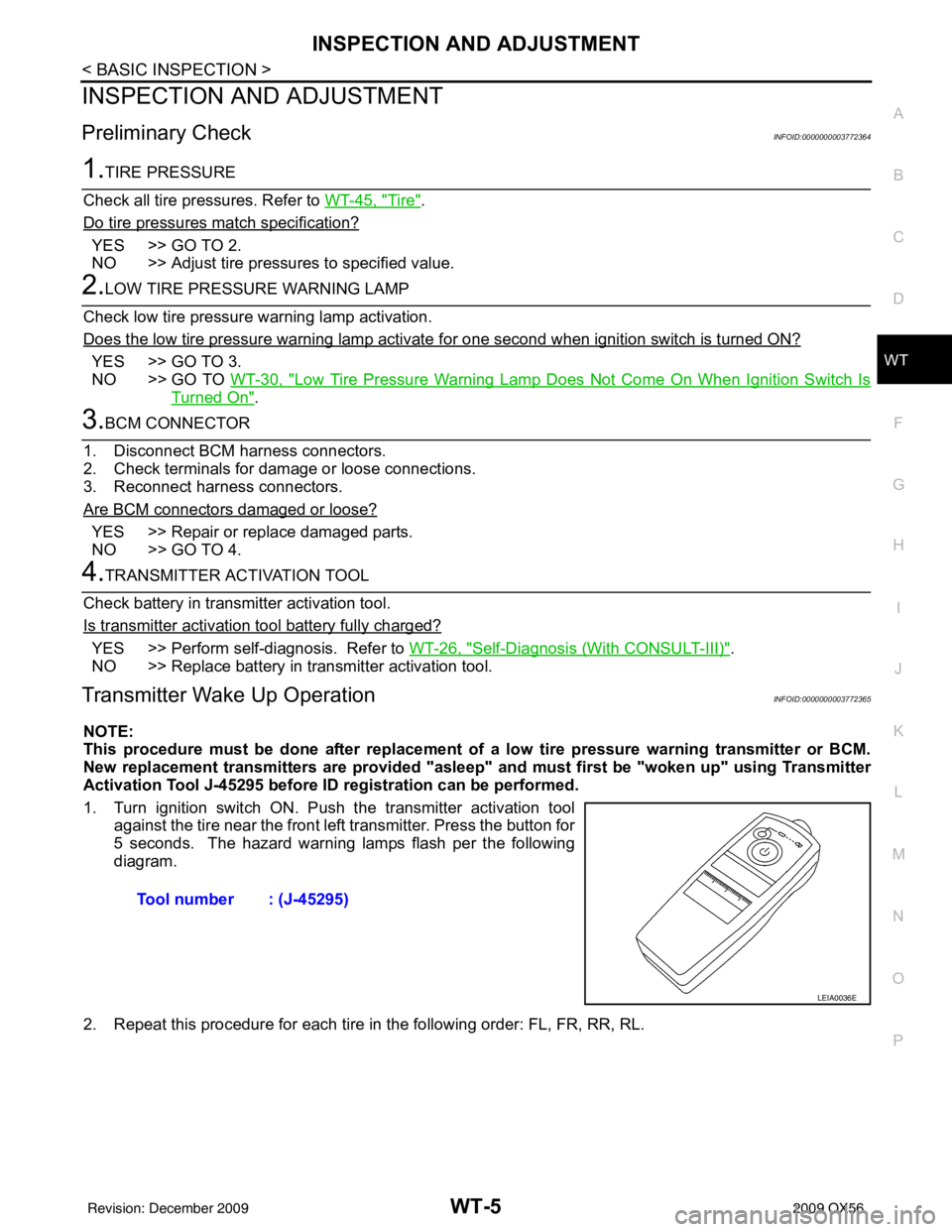
Transmitter Wake Up OperationINFOID:0000000003772365
NOTE:
This procedure must be done after replacement of a low tire pressure warning transmitter or BCM.
New replacement transmitters are provided "asleep" and must first be "woken up" using Transmitter
Activation Tool J-45295 before ID registration can be performed.
1. Turn ignition switch ON. Push the transmitter activation tool against the tire near the front left transmitter. Press the button for
5 seconds. The hazard warning lamps flash per the following
diagram.
2. Repeat this procedure for each tire in the following order: FL, FR, RR, RL. Tool number : (J-45295)
LEIA0036E
Revision: December 20092009 QX56
Page 4050 of 4171

WT-8
< FUNCTION DIAGNOSIS >
TPMS
FUNCTION DIAGNOSIS
TPMS
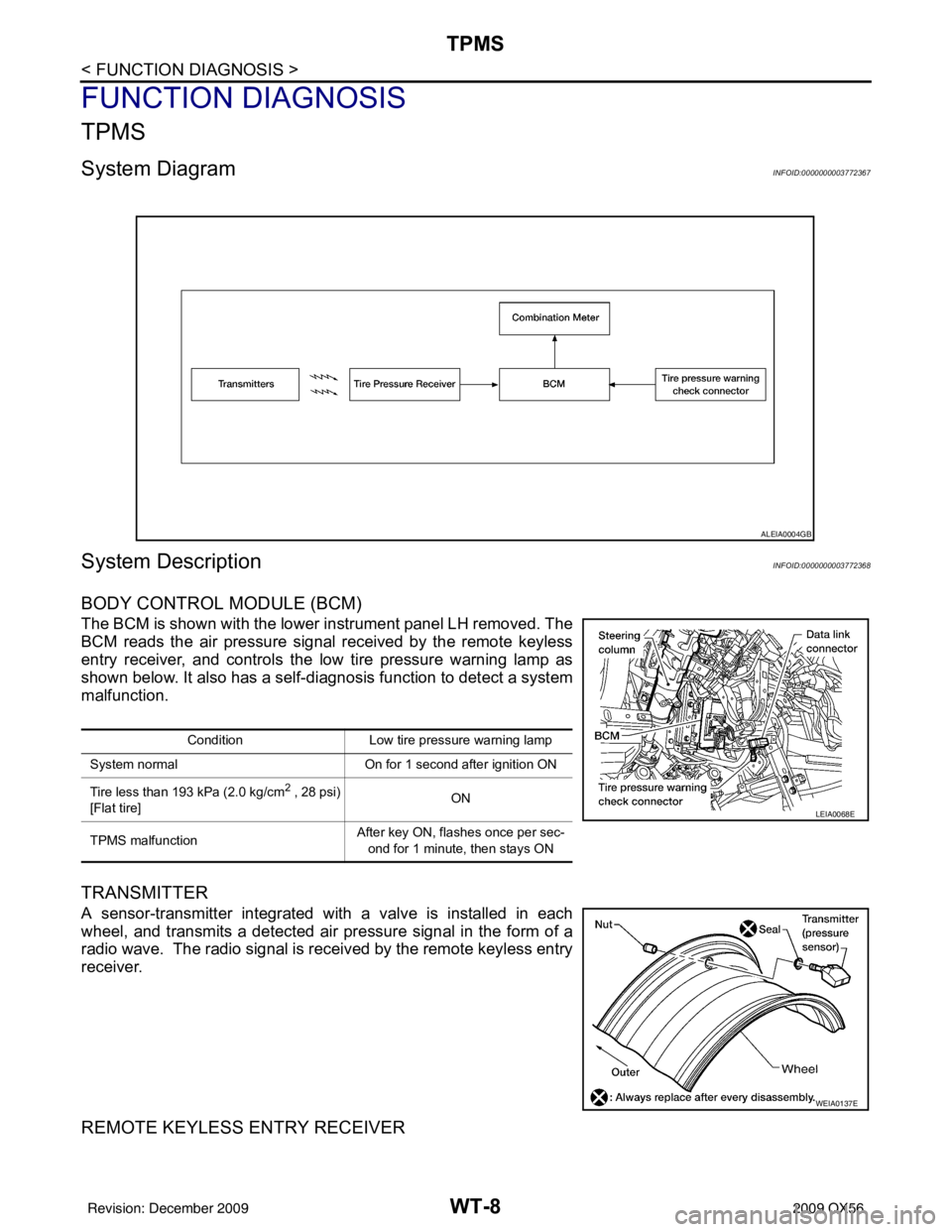
System DiagramINFOID:0000000003772367
System DescriptionINFOID:0000000003772368
BODY CONTROL MODULE (BCM)
The BCM is shown with the lower instrument panel LH removed. The
BCM reads the air pressure signal received by the remote keyless
entry receiver, and controls the low tire pressure warning lamp as
shown below. It also has a self-d iagnosis function to detect a system
malfunction.
TRANSMITTER
A sensor-transmitter integrated with a valve is installed in each
wheel, and transmits a detected air pr essure signal in the form of a
radio wave. The radio signal is received by the remote keyless entry
receiver.
REMOTE KEYLESS ENTRY RECEIVER
ALEIA0004GB
Condition Low tire pressure warning lamp
System normal On for 1 second after ignition ON
Tire less than 193 kPa (2.0 kg/cm
2 , 28 psi)
[Flat tire] ON
TPMS malfunction After key ON, flashes once per sec-
ond for 1 minute, then stays ON
LEIA0068E
WEIA0137E
Revision: December 20092009 QX56
Page 4065 of 4171
BCM (BODY CONTROL MODULE)WT-23
< ECU DIAGNOSIS >
C
DF
G H
I
J
K L
M A
B
WT
N
O P
Wiring DiagramINFOID:0000000003772388
ABEWA0003GB
Revision: December 20092009 QX56