2009 INFINITI QX56 diagram
[x] Cancel search: diagramPage 3600 of 4171
HEATED STEERING WHEELST-9
< COMPONENT DIAGNOSIS >
C
DE
F
H I
J
K L
M A
B
ST
N
O P
COMPONENT DIAGNOSIS
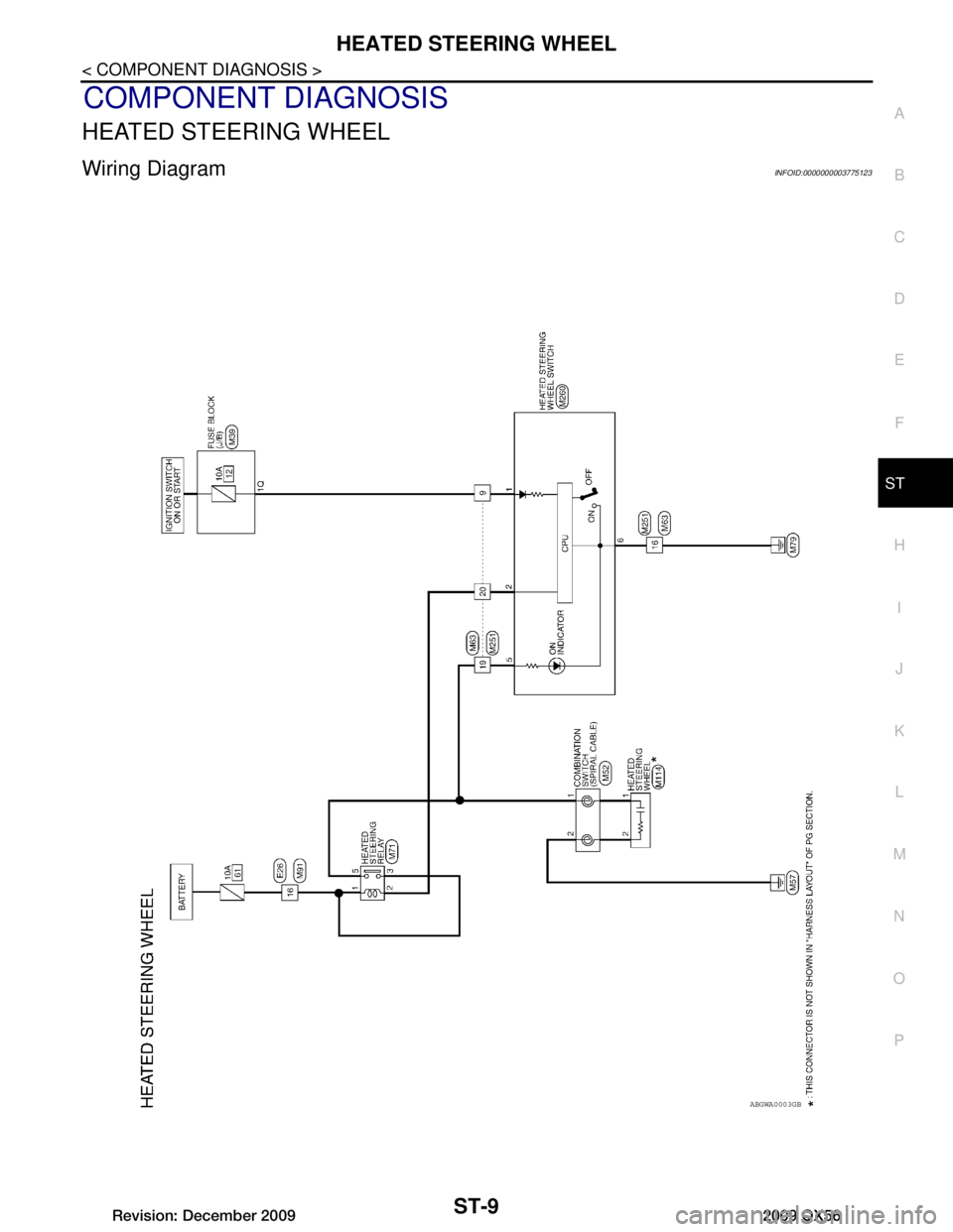
HEATED STEERING WHEEL
Wiring DiagramINFOID:0000000003775123
ABGWA0003GB
Revision: December 20092009 QX56
Page 3630 of 4171

STR-1
ENGINE
C
DE
F
G H
I
J
K L
M
SECTION STR
A
STR
N
O P
CONTENTS
STARTING SYSTEM
PRECAUTION ....... ........................................2
PRECAUTIONS .............................................. .....2
Precaution for Supplemental Restraint System
(SRS) "AIR BAG" and "SEAT BELT PRE-TEN-
SIONER" ............................................................. ......
2
Precaution Necessary for Steering Wheel Rota-
tion After Battery Disconnect ............................... ......
2
Precaution for Power Generation Variable Voltage
Control System ..........................................................
3
PREPARATION ............................................4
PREPARATION .............................................. .....4
Special Service Tool ........................................... ......4
Commercial Service Tool ..........................................4
BASIC INSPECTION ....................................5
DIAGNOSIS AND REPAIR WORKFLOW ..... .....5
Work Flow ........................................................... ......5
FUNCTION DIAGNOSIS ...............................8
STARTING SYSTEM ...................................... .....8
System Diagram .................................................. ......8
System Description ...................................................8
Component Parts Location ........................................8
Component Description ............................................9
COMPONENT DIAGNOSIS .........................10
B TERMINAL CIRCUIT .....................................10
Description ........................................................... ....10
Diagnosis Procedure ...............................................10
S CONNECTOR CIRCUIT .................................11
Description ...............................................................11
Diagnosis Procedure ...............................................11
STARTING SYSTEM .........................................12
Wiring Diagram .................................................... ....12
SYMPTOM DIAGNOSIS ..............................17
STARTING SYSTEM .........................................17
Symptom Table ................................................... ....17
ON-VEHICLE REPAIR .................................18
STARTER MOTOR ...........................................18
Removal and Installation ..................................... ....18
SERVICE DATA AND SPECIFICATIONS
(SDS) ............... .......................................... ...
19
STARTER MOTOR ...........................................19
Starter .................................................................. ....19
Revision: December 20092009 QX56
Page 3637 of 4171
STR-8
< FUNCTION DIAGNOSIS >
STARTING SYSTEM
FUNCTION DIAGNOSIS
STARTING SYSTEM
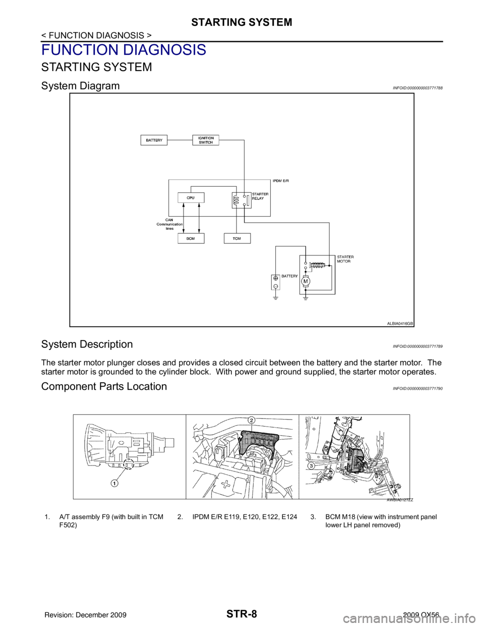
System DiagramINFOID:0000000003771788
System DescriptionINFOID:0000000003771789
The starter motor plunger closes and provides a closed circuit between the battery and the starter motor. The
starter motor is grounded to the cylinder block. With power and ground supplied, the starter motor operates.
Component Parts LocationINFOID:0000000003771790
ALBIA0416GB
1. A/T assembly F9 (with built in TCM
F502) 2. IPDM E/R E119, E120, E122, E124 3. BCM M18 (view with instrument panel
lower LH panel removed)
AWBIA0127ZZ
Revision: December 20092009 QX56
Page 3641 of 4171
STR-12
< COMPONENT DIAGNOSIS >
STARTING SYSTEM
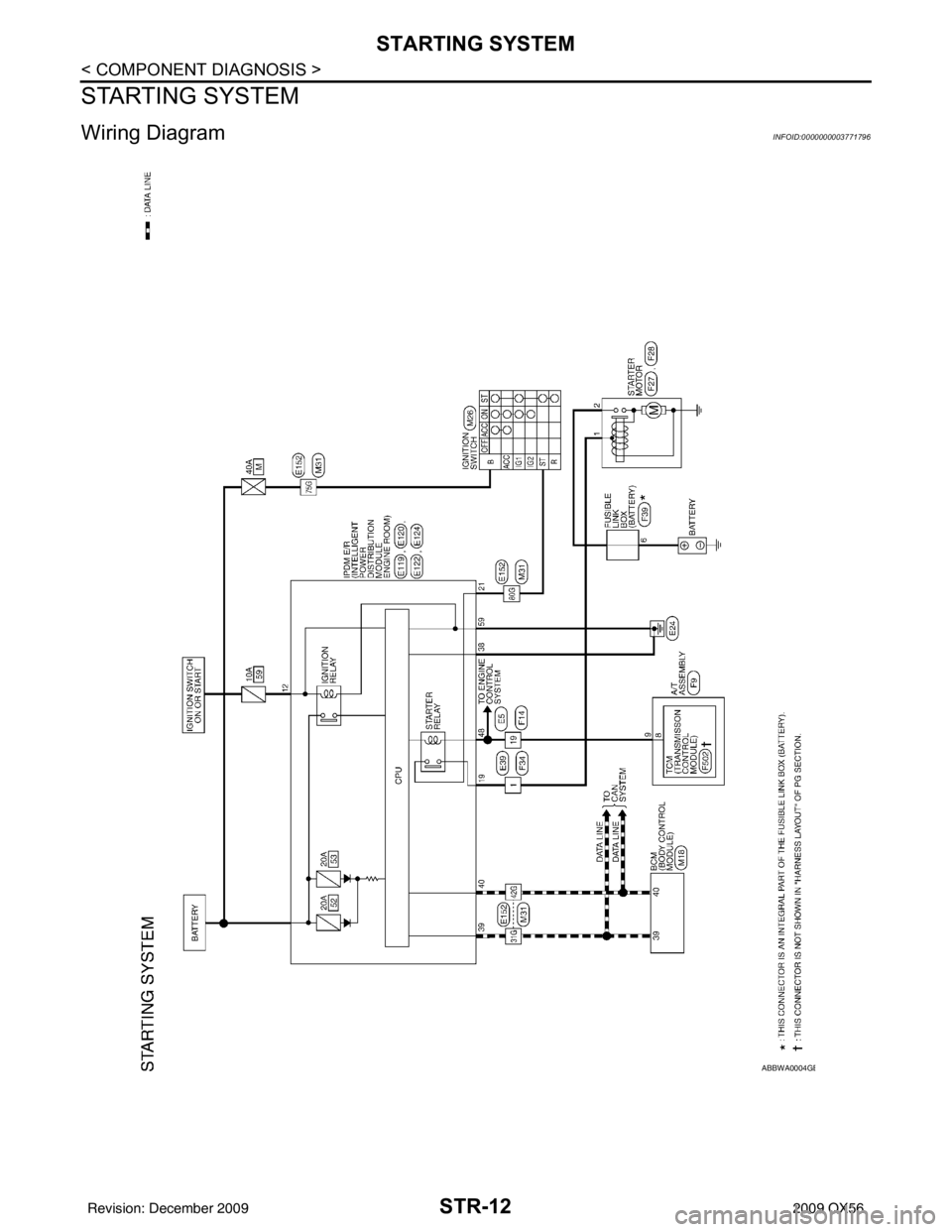
STARTING SYSTEM
Wiring DiagramINFOID:0000000003771796
ABBWA0004GB
Revision: December 20092009 QX56
Page 3651 of 4171

TM-3
CEF
G H
I
J
K L
M A
B
TM
N
O P
Diagnosis Procedure ...........................................
....
78
P1752 INPUT CLUTCH SOLENOID ..................80
Description .......................................................... ....80
CONSULT-III Reference Value in Data Monitor
Mode ................................................................... ....
80
On Board Diagnosis Logic ......................................80
Possible Cause .......................................................80
DTC Confirmation Procedure ..................................80
Diagnosis Procedure ...............................................80
P1757 FRONT BRAKE SOLENOID ...................82
Description .......................................................... ....82
CONSULT-III Reference Value in Data Monitor
Mode ................................................................... ....
82
On Board Diagnosis Logic ......................................82
Possible Cause .......................................................82
DTC Confirmation Procedure ..................................82
Diagnosis Procedure ...............................................82
P1762 DIRECT CLUTCH SOLENOID ................84
Description .......................................................... ....84
CONSULT-III Reference Value in Data Monitor
Mode ................................................................... ....
84
On Board Diagnosis Logic ......................................84
Possible Cause .......................................................84
DTC Confirmation Procedure ..................................84
Diagnosis Procedure ...............................................84
P1767 HIGH AND LOW REVERSE CLUTCH
SOLENOID .........................................................
86
Description .......................................................... ....86
CONSULT-III Reference Value in Data Monitor
Mode ................................................................... ....
86
On Board Diagnosis Logic ......................................86
Possible Cause .......................................................86
DTC Confirmation Procedure ..................................86
Diagnosis Procedure ...............................................86
P1772 LOW COAST BRAKE SOLENOID .........88
Description .......................................................... ....88
CONSULT-III Reference Value in Data Monitor
Mode ................................................................... ....
88
On Board Diagnosis Logic ......................................88
Possible Cause .......................................................88
DTC Confirmation Procedure ..................................88
Diagnosis Procedure ...............................................88
P1774 LOW COAST BRAKE SOLENOID .........90
Description .......................................................... ....90
CONSULT-III Reference Value in Data Monitor
Mode ................................................................... ....
90
On Board Diagnosis Logic ......................................90
Possible Cause .......................................................90
DTC Confirmation Procedure ..................................90
Diagnosis Procedure ...............................................90
MAIN POWER SUPPLY AND GROUND CIR-
CUIT ....................................................................
92
Diagnosis Procedure ........................................... ....92
CLOSED THROTTLE POSITION AND WIDE
OPEN THROTTLE POSITION CIRCUIT ...........
94
CONSULT-III Reference Value in Data Monitor
Mode .................................................................... ....
94
Diagnosis Procedure ...............................................94
BRAKE SIGNAL CIRCUIT ................................95
CONSULT-III Reference Value in Data Monitor
Mode .................................................................... ....
95
Diagnosis Procedure ...............................................95
TOW MODE SWITCH .......................................96
Description ...............................................................96
Diagnosis Procedure ...............................................96
A/T SHIFT LOCK SYSTEM ...............................97
Wiring Diagram - A/T Shift Lock System .................97
Terminals And Reference Values ..........................101
Component Description .........................................101
ECU DIAGNOSIS .......................................104
TCM .................................................................104
Reference Value .................................................. ..104
Wiring Diagram — A/T CONTROL SYSTEM — .. ..106
Fail-Safe .............................................................. ..115
DTC Inspection Priority Chart ................................117
DTC No. Index .......................................................117
DTC Alphabetical Index .........................................118
SYMPTOM DIAGNOSIS ............................119
SYSTEM SYMPTOM .......................................119
A/T Check Indicator Lamp Does Not Come On ... ..119
Engine Cannot Be Started in "P" or "N" Position ...119
In "P" Position, Vehicle Moves When Pushed .......120
In "N" Position, Vehicle Moves ..............................120
Large Shock("N" to "D" Position) ...........................122
Vehicle Does Not Creep Backward in "R" Position ..124
Vehicle Does Not Creep Forward in "D" Position ..126
Vehicle Cannot Be Started from D1 ......................129
A/T Does Not Shift: D1ÆD2 ..................................131
A/T Does Not Shift: D2ÆD3 ..................................132
A/T Does Not Shift: D3ÆD4 ..................................134
A/T Does Not Shift: D4ÆD5 ..................................136
A/T Does Not Perform Lock-up .............................138
A/T Does Not Hold Lock-up Condition ...................140
Lock-up Is Not Released .......................................141
Engine Speed Does Not Return to Idle .................142
A/T Does Not Shift: 5GR Æ 4GR ..........................143
A/T Does Not Shift: 4GR Æ 3GR ..........................145
A/T Does Not Shift: 3GR Æ 2GR ..........................147
A/T Does Not Shift: 2GR Æ 1GR ..........................148
Vehicle Does Not Decelerate By Engine Brake .....150
Symptom Table .....................................................152
PRECAUTION ............................................174
PRECAUTIONS ...............................................174
Revision: December 20092009 QX56
Page 3669 of 4171
A/T CONTROL SYSTEMTM-21
< FUNCTION DIAGNOSIS >
CEF
G H
I
J
K L
M A
B
TM
N
O P
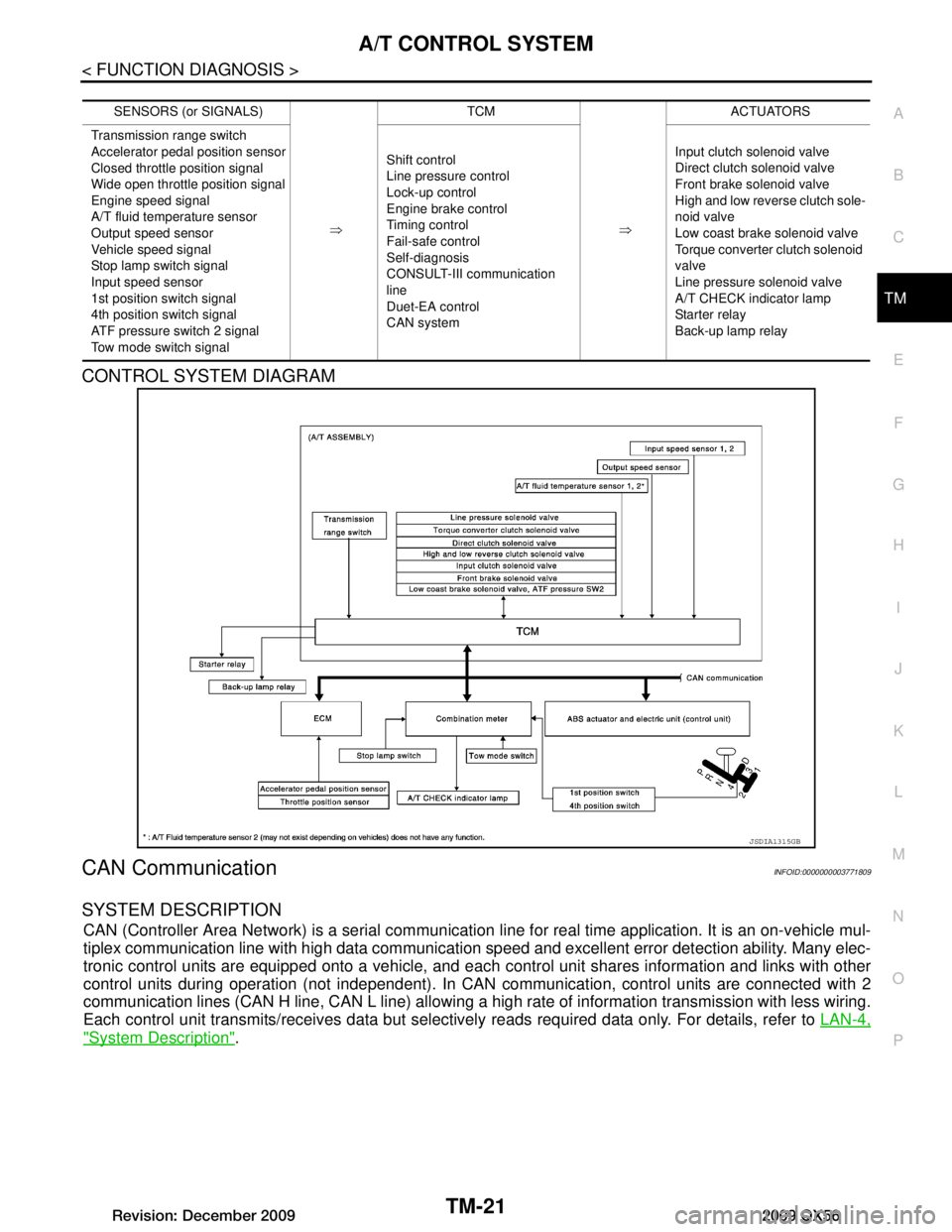
CONTROL SYSTEM DIAGRAM
CAN CommunicationINFOID:0000000003771809
SYSTEM DESCRIPTION
CAN (Controller Area Network) is a serial communication li ne for real time application. It is an on-vehicle mul-
tiplex communication line with high data communication speed and excellent error detection ability. Many elec-
tronic control units are equipped onto a vehicle, and each control unit shares information and links with other
control units during operation (not independent). In CAN communication, control units are connected with 2
communication lines (CAN H line, CAN L line) allowing a high rate of information transmission with less wiring.
Each control unit transmits/receives data but selectively reads required data only. For details, refer to LAN-4,
"System Description".
SENSORS (or SIGNALS)
⇒TCM
⇒ACTUATORS
Transmission range switch
Accelerator pedal position sensor
Closed throttle position signal
Wide open throttle position signal
Engine speed signal
A/T fluid temperature sensor
Output speed sensor
Vehicle speed signal
Stop lamp switch signal
Input speed sensor
1st position switch signal
4th position switch signal
ATF pressure switch 2 signal
Tow mode switch signal Shift control
Line pressure control
Lock-up control
Engine brake control
Timing control
Fail-safe control
Self-diagnosis
CONSULT-III co
mmunication
line
Duet-EA control
CAN system Input clutch solenoid valve
Direct clutch solenoid valve
Front brake solenoid valve
High and low reverse clutch sole-
noid valve
Low coast brake solenoid valve
Torque converter clutch solenoid
valve
Line pressure solenoid valve
A/T CHECK indicator lamp
Starter relay
Back-up lamp relay
JSDIA1315GB
Revision: December 20092009 QX56
Page 3672 of 4171
TM-24
< FUNCTION DIAGNOSIS >
A/T CONTROL SYSTEM
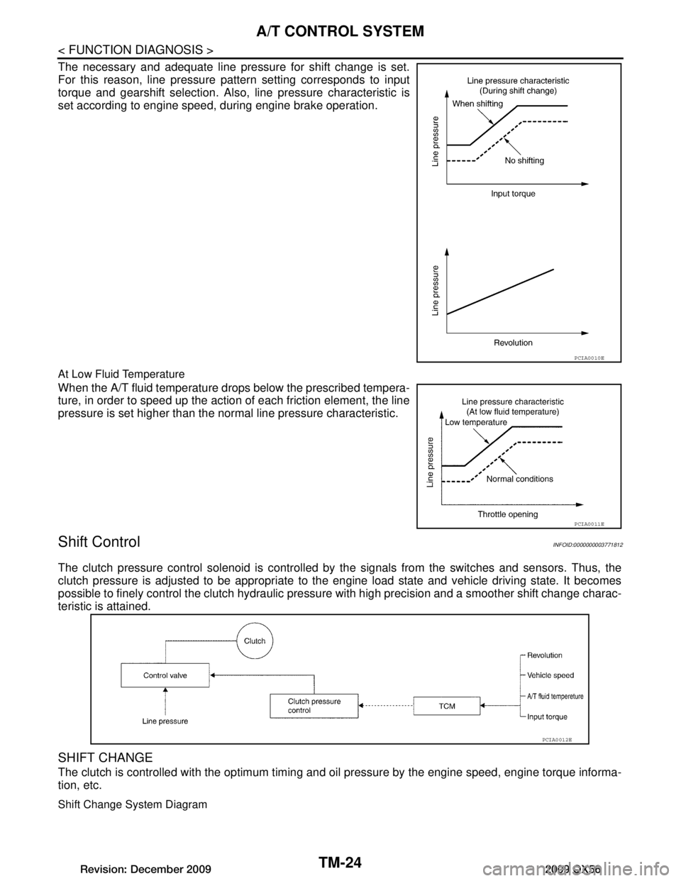
The necessary and adequate line pressure for shift change is set.
For this reason, line pressure pattern setting corresponds to input
torque and gearshift selection. Also, line pressure characteristic is
set according to engine speed, during engine brake operation.
At Low Fluid Temperature
When the A/T fluid temperature drops below the prescribed tempera-
ture, in order to speed up the action of each friction element, the line
pressure is set higher than the normal line pressure characteristic.
Shift ControlINFOID:0000000003771812
The clutch pressure control solenoid is controlled by the signals from the switches and sensors. Thus, the
clutch pressure is adjusted to be appropriate to the engine load state and vehicle driving state. It becomes
possible to finely control the clutch hydraulic pressu re with high precision and a smoother shift change charac-
teristic is attained.
SHIFT CHANGE
The clutch is controlled with the optimum timing and oil pressure by the engine speed, engine torque informa-
tion, etc.
Shift Change System Diagram
PCIA0010E
PCIA0011E
PCIA0012E
Revision: December 20092009 QX56
Page 3673 of 4171
A/T CONTROL SYSTEMTM-25
< FUNCTION DIAGNOSIS >
CEF
G H
I
J
K L
M A
B
TM
N
O P
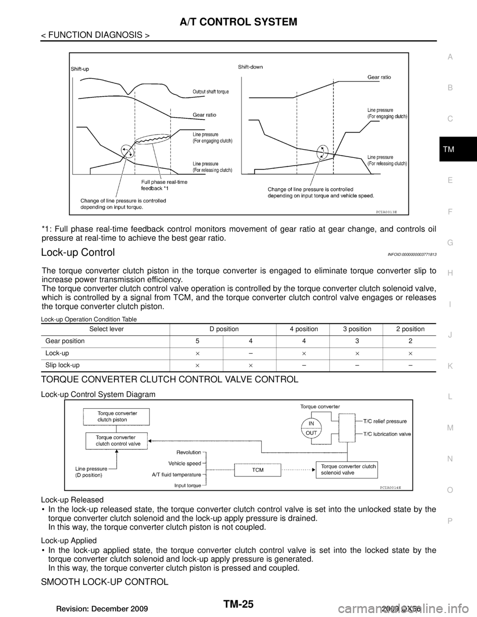
*1: Full phase real-time feedback control monitors move ment of gear ratio at gear change, and controls oil
pressure at real-time to achieve the best gear ratio.
Lock-up ControlINFOID:0000000003771813
The torque converter clutch piston in the torque conv erter is engaged to eliminate torque converter slip to
increase power transmission efficiency.
The torque converter clutch control valve operation is c ontrolled by the torque converter clutch solenoid valve,
which is controlled by a signal from TCM, and the to rque converter clutch control valve engages or releases
the torque converter clutch piston.
Lock-up Operation Condition Table
TORQUE CONVERTER CLUTCH CONTROL VALVE CONTROL
Lock-up Control System Diagram
Lock-up Released
In the lock-up released state, the torque converter clutch control valve is set into the unlocked state by the
torque converter clutch solenoid and the lock-up apply pressure is drained.
In this way, the torque converter clutch piston is not coupled.
Lock-up Applied
In the lock-up applied state, the torque converter clutch control valve is set into the locked state by the
torque converter clutch solenoid and lock-up apply pressure is generated.
In this way, the torque converter clutch piston is pressed and coupled.
SMOOTH LOCK-UP CONTROL
PCIA0013E
Select lever D position 4 position 3 position 2 position
Gear position 54432
Lock-up ×– ×××
Slip lock-up ××–––
PCIA0014E
Revision: December 20092009 QX56