2009 INFINITI QX56 ECO mode
[x] Cancel search: ECO modePage 3736 of 4171
TM-88
< COMPONENT DIAGNOSIS >
P1772 LOW COAST BRAKE SOLENOID
P1772 LOW COAST BRAKE SOLENOID
DescriptionINFOID:0000000003771963
Low coast brake solenoid valve is turned “ON” or “OFF” by the TCM in response to signals sent from the trans-
mission range switch, output speed sensor and accelerato r pedal position sensor (throttle position sensor).
Gears will then be shifted to the optimum position.
CONSULT-III Reference Value in Data Monitor ModeINFOID:0000000003771964
On Board Diagn osis LogicINFOID:0000000003771965
This is an OBD-II self-diagnostic item.
Diagnostic trouble code “P1772” with CONSULT-III is detected when TCM detects an improper voltage drop
when it tries to operate the solenoid valve.
Possible CauseINFOID:0000000003771966
Harness or connectors (The solenoid circuit is open or shorted.)
Low coast brake solenoid valve
DTC Confirmation ProcedureINFOID:0000000003771967
NOTE:
If “DTC Confirmation Procedure” has been previously performed, always turn ignition switch “OFF”
and wait at least 10 seconds before performing the next test.
After the repair, perform the following proc edure to confirm the malfunction is eliminated.
WITH CONSULT-III
1. Turn ignition switch “ON”. (Do not start engine.)
2. Select “DATA MONITOR” mode for “ENGINE” with CONSULT-III.
3. Start engine.
4. Drive vehicle and maintain the following conditions for at least 5 consecutive seconds.
SLCT LVR POSI: “1” or “2”
GEAR: “1st” or “2nd” (LC/B ON/OFF)
5. If DTC is detected, go to TM-88, "Diagnosis Procedure"
.
WITH GST
Follow the procedure “With CONSULT-III”.
Diagnosis ProcedureINFOID:0000000003771968
1.CHECK INPUT SIGNAL
With CONSULT-III
1. Turn ignition switch “ON”.
2. Select “SELECTION FROM MENU” in “DATA MONI TOR” mode for “TRANSMISSION” with CONSULT-III.
3. Start the engine.
4. Read out the value of “ON OFF SOL” while driving.
OK or NG
OK >> GO TO 4.
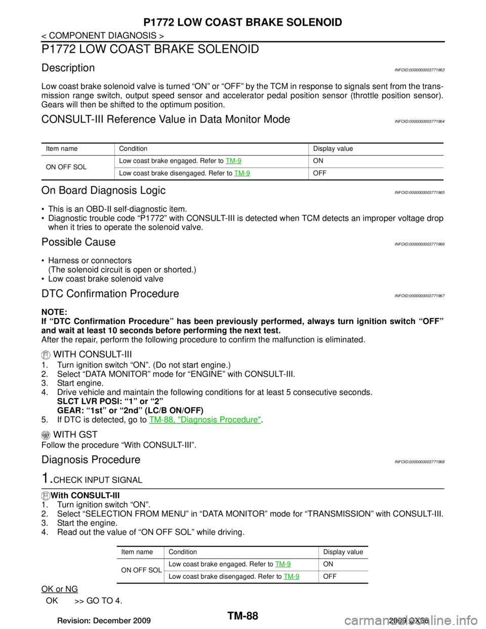
Item name Condition Display value
ON OFF SOL Low coast brake engaged. Refer to
TM-9
ON
Low coast brake disengaged. Refer to TM-9
OFF
Item name Condition Display value
ON OFF SOLLow coast brake engaged. Refer to
TM-9
ON
Low coast brake disengaged. Refer to TM-9
OFF
Revision: December 20092009 QX56
Page 3738 of 4171
TM-90
< COMPONENT DIAGNOSIS >
P1774 LOW COAST BRAKE SOLENOID
P1774 LOW COAST BRAKE SOLENOID
DescriptionINFOID:0000000003771969
Low coast brake solenoid valve is turned “ON” or “OFF” by the TCM in response to signals sent from the
transmission range switch, output speed sensor and accele rator pedal position sensor (throttle position sen-
sor). Gears will then be shifted to the optimum position.
This is not only caused by electrical malfunction (cir cuits open or shorted) but also by mechanical malfunc-
tion such as control valve sticking, improper solenoid valve operation.
CONSULT-III Reference Value in Data Monitor ModeINFOID:0000000003771970
On Board Diagn osis LogicINFOID:0000000003771971
This is an OBD-II self-diagnostic item.
Diagnostic trouble code “P1774” with CONSULT-III is detected under the following conditions.
- When TCM detects that actual gear ratio is irr egular, and relation between gear position and condition of
ATF pressure switch 2 is irregular during depressing accelerator pedal. (Other than during shift change)
- When TCM detects that relation between gear position and condition of ATF pressure switch 2 is irregular
during releasing accelerator pedal. (Other than during shift change)
Possible CauseINFOID:0000000003771972
Harness or connectors
(The solenoid and switch circuits are open or shorted.)
Low coast brake solenoid valve
ATF pressure switch 2
DTC Confirmation ProcedureINFOID:0000000003771973
CAUTION:
Always drive vehicle at a safe speed.
NOTE:
If “DTC Confirmation Procedure” has been previously performed, always turn ignition switch “OFF”
and wait at least 10 seconds before performing the next test.
After the repair, perform the following proc edure to confirm the malfunction is eliminated.
WITH CONSULT-III
1. Start engine.
2. Accelerate vehicle to maintain the following conditions.
SLCT LVR POSI: “1” or “2” position
GEAR: “1st” or “2nd” (LC/B ON/OFF)
3. Perform step “2” again.
4. Turn ignition switch “OFF”, then perform step “1” to “3” again.
5. Check “SELF-DIAG RESULTS” mode for “TRANS MISSION” with CONSULT-III. If DTC (P1774) is
detected, refer to TM-90, "Diagnosis Procedure"
.
If DTC (P1772) is detected, go to TM-88, "Diagnosis Procedure"
.
WITH GST
Follow the procedure “With CONSULT-III”.
Diagnosis ProcedureINFOID:0000000003771974
1.CHECK INPUT SIGNALS
Item name Condition Display value
ON OFF SOLLow coast brake engaged. Refer to
TM-9
ON
Low coast brake disengaged. Refer to TM-9
OFF
ATF PRES SW 2 Low coast brake engaged. Refer to
TM-9
ON
Low coast brake disengaged. Refer to TM-9
OFF
Revision: December 20092009 QX56
Page 3764 of 4171

TM-116
< ECU DIAGNOSIS >
TCM
Even when the electronic circuits are normal, under special conditions (for example, when slamming on the
brake with the wheels spinning drastically and stopping t he tire rotation), the transmission can go into fail-safe
mode. If this happens, switch “OFF” the ignition switch for 10 seconds, then switch it “ON” again to return to
the normal shift pattern. Therefore, the customer's v ehicle has returned to normal, so handle according to the
“diagnostics flow” (Refer to TM-5, "Work Flow"
).
FAIL-SAFE FUNCTION
If any malfunction occurs in a sensor or solenoid, th is function controls the A/T to mark driving possible.
Output Speed Sensor
Signals are input from two systems - from output s peed sensor installed on the transmission and from com-
bination meter so normal driving is possible even if ther e is a malfunction in one of the systems. And if output
speed sensor has unusual cases, 5GR is prohibited.
Accelerator Peda l Position Sensor
If there is a malfunction in one of the systems, the accelerator opening angle is controlled by ECM according
to a pre-determined accelerator angle to make driving possible. And if there are malfunctions in tow sys-
tems, the engine speed is fixed by ECM to a pre-determined engine speed to make driving possible.
Throttle Position Sensor
If there is a malfunction in one of the systems, the accelerator opening angle is controlled by ECM according
to a pre-determined accelerator angle to make driving possible. And if there are malfunctions in tow sys-
tems, the accelerator opening angle is controlled by the idle signal sent from the ECM which is based on
input indicating either idle condition or off-idle condition (pre-determined accelerator opening) in order to
make driving possible.
Transmission Range Switch
In the unlikely event that a malfunction signal enters t he TCM, the position indicator is switched “OFF”, the
starter relay is switched “OFF” (starter starting is disabled), the back-up lamp relay switched “OFF” (back-up
lamp is OFF) and the position is fixed to the “D” range to make driving possible.
Starter Relay
The starter relay is switched “OFF”. (Starter starting is disabled.)
Interlock
If there is an interlock judgment malfunction, the trans mission is fixed in 2GR to make driving possible.
NOTE:
When the vehicle is driven fixed in 2GR, a input speed sensor malfunction is displayed, but this is
not a input speed sensor malfunction.
When the interlock is detected at the 3GR or more, it is locked at the 2GR.
1st Engine Braking
When there is an 1st gear engine brake judgment malfunc tion, the low coast brake solenoid is switched
“OFF” to avoid the engine brake operation.
Line Pressure Solenoid
The solenoid is switched “OFF” and the line pressure is se t to the maximum hydraulic pressure to make driv-
ing possible.
Torque Converter Clutch Solenoid
The solenoid is switched “OFF” to release the lock-up.
Low Coast Brake Solenoid
When a (electrical or functional) malfunction occurs, in order to make driving possible, the engine brake is not applied in 1GR and 2GR.
Input Clutch Solenoid
If a (electrical or functional) malfunction occurs with the solenoid either “ON” or “OFF”, the transmission is
held in 4GR to make driving possible.
Direct Clutch Solenoid
If a (electrical or functional) malfunction occurs with the solenoid either “ON” or “OFF”, the transmission is
held in 4GR to make driving possible.
Front Brake Solenoid
If a (electrical or functional) malfunction occurs with the solenoid “ON”, in order to make driving possible, the
A/T is held in 5GR; if the solenoid is OFF, 4GR.
Revision: December 20092009 QX56
Page 3822 of 4171

TM-174
< PRECAUTION >
PRECAUTIONS
PRECAUTION
PRECAUTIONS
Precaution for Supplemental Restraint System (SRS) "AIR BAG" and "SEAT BELT
PRE-TENSIONER"
INFOID:0000000005880175
The Supplemental Restraint System such as “A IR BAG” and “SEAT BELT PRE-TENSIONER”, used along
with a front seat belt, helps to reduce the risk or severi ty of injury to the driver and front passenger for certain
types of collision. This system includes seat belt switch inputs and dual stage front air bag modules. The SRS
system uses the seat belt switches to determine the front air bag deployment, and may only deploy one front
air bag, depending on the severity of a collision and w hether the front occupants are belted or unbelted.
Information necessary to service the system safely is included in the SR and SB section of this Service Man-
ual.
WARNING:
To avoid rendering the SRS inopera tive, which could increase the risk of personal injury or death in
the event of a collision which would result in air bag inflation, all maintenance must be performed by
an authorized NISS AN/INFINITI dealer.
Improper maintenance, including in correct removal and installation of the SRS, can lead to personal
injury caused by unintent ional activation of the system. For re moval of Spiral Cable and Air Bag
Module, see the SR section.
Do not use electrical test equipmen t on any circuit related to the SRS unless instructed to in this
Service Manual. SRS wiring harnesses can be identi fied by yellow and/or orange harnesses or har-
ness connectors.
PRECAUTIONS WHEN USING POWER TOOLS (AIR OR ELECTRIC) AND HAMMERS
WARNING:
When working near the Airbag Diagnosis Sensor Unit or other Airbag System sensors with the Igni-
tion ON or engine running, DO NOT use air or electri c power tools or strike near the sensor(s) with a
hammer. Heavy vibration could activate the sensor( s) and deploy the air bag(s), possibly causing
serious injury.
When using air or electric power tools or hammers , always switch the Ignition OFF, disconnect the
battery, and wait at least 3 minu tes before performing any service.
Precaution Necessary for Steering W heel Rotation After Battery Disconnect
INFOID:0000000005880176
NOTE:
This Procedure is applied only to models with Intelli gent Key system and NATS (NISSAN ANTI-THEFT SYS-
TEM).
Remove and install all control units after disconnecting both battery cables with the ignition knob in the
″LOCK ″ position.
Always use CONSULT-III to perform self-diagnosis as a part of each function inspection after finishing work.
If DTC is detected, perform trouble diagnosis according to self-diagnostic results.
For models equipped with the Intelligent Key system and NATS, an electrically controlled steering lock mech-
anism is adopted on the key cylinder.
For this reason, if the battery is disconnected or if the battery is discharged, the steering wheel will lock and
steering wheel rotation will become impossible.
If steering wheel rotation is required when battery pow er is interrupted, follow the procedure below before
starting the repair operation.
OPERATION PROCEDURE
1. Connect both battery cables. NOTE:
Supply power using jumper cables if battery is discharged.
2. Use the Intelligent Key or mechanical key to turn the ignition switch to the ″ACC ″ position. At this time, the
steering lock will be released.
3. Disconnect both battery cables. The steering lock will remain released and the steering wheel can be
rotated.
4. Perform the necessary repair operation.
Revision: December 20092009 QX56
Page 3823 of 4171
PRECAUTIONSTM-175
< PRECAUTION >
CEF
G H
I
J
K L
M A
B
TM
N
O P
5. When the repair work is completed, return the ignition switch to the ″LOCK ″ position before connecting
the battery cables. (At this time, the steering lock mechanism will engage.)
6. Perform a self-diagnosis check of al l control units using CONSULT-III.
Precaution for On Board Diagnosis (OBD) System of A/T and EngineINFOID:0000000003772014
The ECM has an on board diagnostic system. It will light up the malfunction indicator lamp (MIL) to warn the
driver of a malfunction causing emission deterioration.
CAUTION:
Be sure to turn the ignition sw itch “OFF” and disconnect the negati ve battery cable before any repair
or inspection work. The open/short circuit of related switches, sensors, solenoid valves, etc. Will
cause the MIL to light up.
Be sure to connect and lock the connectors secure ly after work. A loose (unlocked) connector will
cause the MIL to light up due to an open circuit. (Be sure the connector is free from water, grease,
dirt, bent terminals, etc.)
Be sure to route and secure the harnesses properly after work. Interference of the harness with a
bracket, etc. May cause the MIL to li ght up due to a short circuit.
Be sure to connect rubber tubes properly afte r work. A misconnected or disconnected rubber tube
may cause the MIL to light up due to a malfunction of the EGR system or fuel injection system, etc.
Be sure to erase the unnecessary malfunction informa tion (repairs completed) from the TCM and
ECM before returning the vehicle to the customer.
PrecautionINFOID:0000000003772015
NOTE:
If any malfunctions occur in th e RE5R05A model transmission, repl ace the entire transmission assem-
bly.
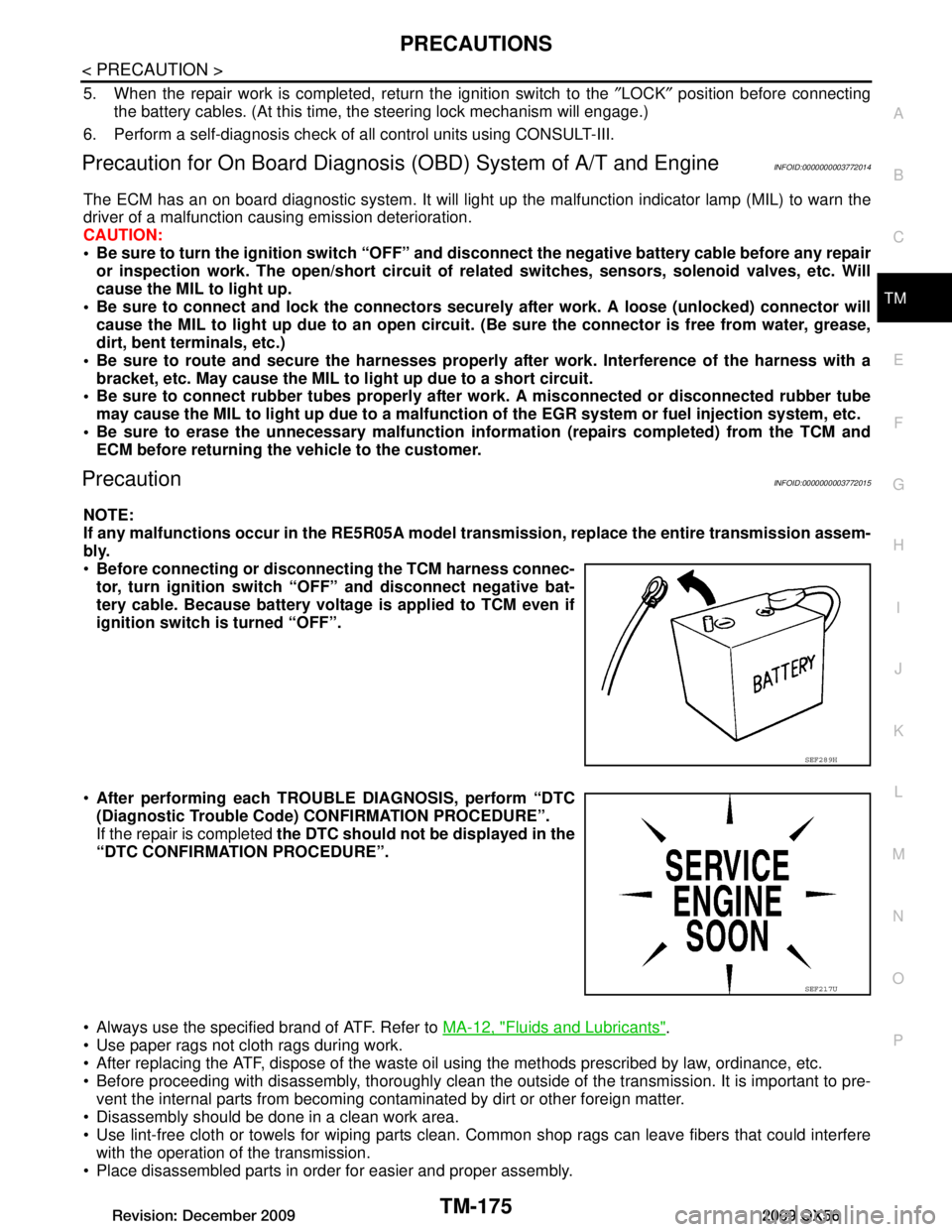
Before connecting or disconn ecting the TCM harness connec-
tor, turn ignition switch “O FF” and disconnect negative bat-
tery cable. Because battery voltage is applied to TCM even if
ignition switch is turned “OFF”.
After performing each TROUBL E DIAGNOSIS, perform “DTC
(Diagnostic Trouble Code) CONFIRMATION PROCEDURE”.
If the repair is completed the DTC should not be displayed in the
“DTC CONFIRMATION PROCEDURE”.
Always use the specified brand of ATF. Refer to MA-12, "Fluids and Lubricants"
.
Use paper rags not cloth rags during work.
After replacing the ATF, dispose of the waste oil using the methods prescribed by law, ordinance, etc.
Before proceeding with disassembly, thoroughly clean the outsi de of the transmission. It is important to pre-
vent the internal parts from becoming contaminated by dirt or other foreign matter.
Disassembly should be done in a clean work area.
Use lint-free cloth or towels for wiping parts clean. Common shop rags can leave fibers that could interfere
with the operation of the transmission.
Place disassembled parts in order for easier and proper assembly.
SEF289H
SEF217U
Revision: December 20092009 QX56
Page 3923 of 4171
ASSEMBLYTM-275
< DISASSEMBLY AND ASSEMBLY >
CEF
G H
I
J
K L
M A
B
TM
N
O P
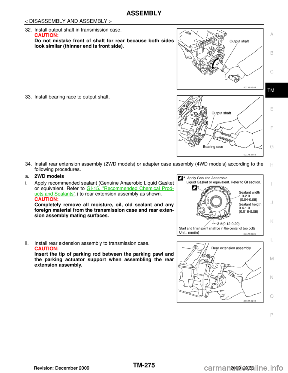
32. Install output shaft in transmission case. CAUTION:
Do not mistake front of shaft for rear because both sides
look similar (thinner end is front side).
33. Install bearing race to output shaft.
34. Install rear extension assembly (2WD models) or adapter case assembly (4WD models) according to the following procedures.
a. 2WD models
i. Apply recommended sealant (Genuine Anaerobic Liquid Gasket or equivalent. Refer to GI-15, "Recommended Chemical Prod-
ucts and Sealants".) to rear extension assembly as shown.
CAUTION:
Completely remove all moisture, oil, old sealant and any
foreign material from the transmission case and rear exten-
sion assembly mating surfaces.
ii. Install rear extension assembly to transmission case. CAUTION:
Insert the tip of parking rod between the parking pawl and
the parking actuator suppor t when assembling the rear
extension assembly.
SCIA5030E
SCIA5245E
SCIA5212E
SCIA5029E
Revision: December 20092009 QX56
Page 3938 of 4171
TM-290
< SERVICE DATA AND SPECIFICATIONS (SDS)
SERVICE DATA AND SPECIFICATIONS (SDS)
SERVICE DATA AND SPECIFICATIONS (SDS)
SERVICE DATA AND SPECIFICATIONS (SDS)
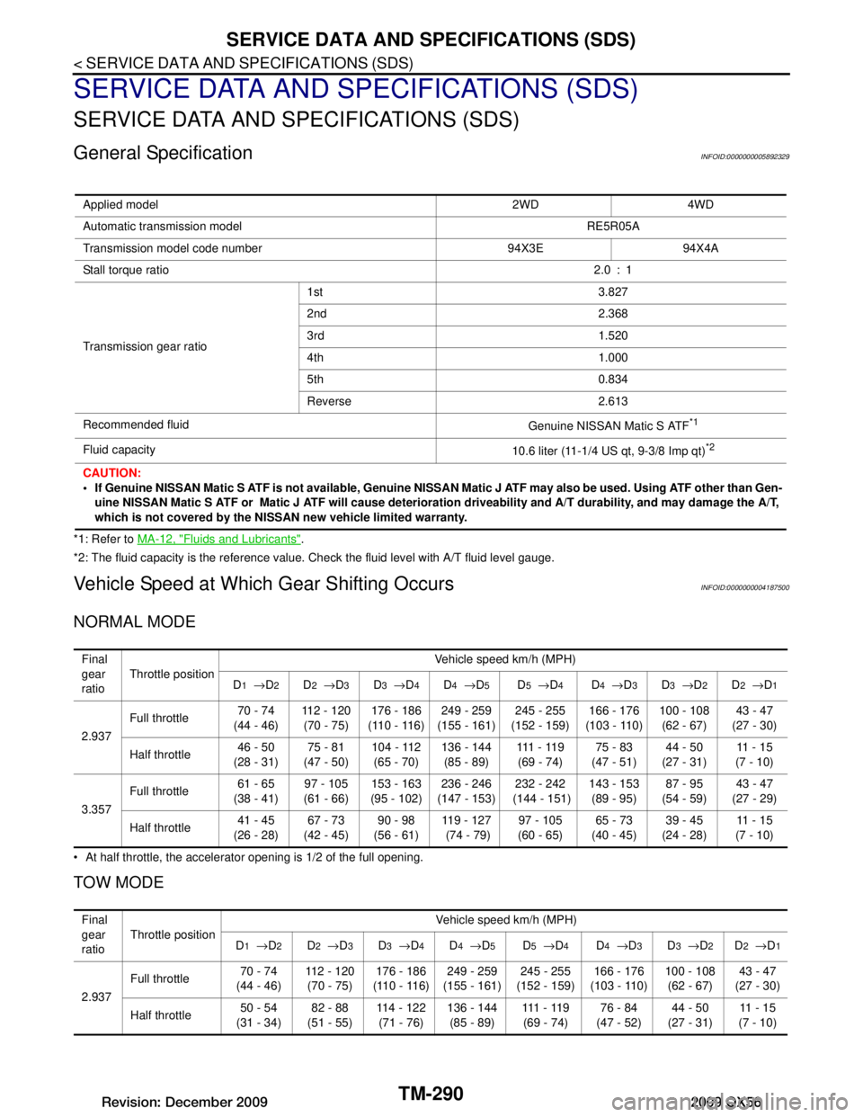
General SpecificationINFOID:0000000005892329
*1: Refer to MA-12, "Fluids and Lubricants".
*2: The fluid capacity is the reference value. Check the fluid level with A/T fluid level gauge.
Vehicle Speed at Which Gear Shifting OccursINFOID:0000000004187500
NORMAL MODE
At half throttle, the accelerator opening is 1/2 of the full opening.
TOW MODE
Applied model 2WD 4WD
Automatic transmission model RE5R05A
Transmission model code number 94X3E 94X4A
Stall torque ratio 2.0 : 1
Transmission gear ratio 1st 3.827
2nd 2.368
3rd 1.520
4th 1.000
5th 0.834
Reverse 2.613
Recommended fluid Genuine NISSAN Matic S ATF
*1
Fluid capacity10.6 liter (11-1/4 US qt, 9-3/8 Imp qt)*2
CAUTION:
If Genuine NISSAN Matic S ATF is not available, Genuine NISSAN Matic J ATF may also be used. Using ATF other than Gen-
uine NISSAN Matic S ATF or Matic J ATF will cause deterioration driveability and A/T durability, and may damage the A/T,
which is not covered by the NISSAN new vehicle limited warranty.
Final
gear
ratio Throttle position
Vehicle speed km/h (MPH)
D
1 → D2D2 → D3D3 → D4D4 → D5D5 → D4D4 → D3D3 → D2D2 → D1
2.937 Full throttle
70 - 74
(44 - 46) 112 - 120
(70 - 75) 176 - 186
(110 - 116) 249 - 259
(155 - 161) 245 - 255
(152 - 159) 166 - 176
(103 - 110) 100 - 108
(62 - 67) 43 - 47
(27 - 30)
Half throttle 46 - 50
(28 - 31) 75 - 81
(47 - 50) 104 - 112
(65 - 70) 136 - 144
(85 - 89) 111 - 11 9
(69 - 74) 75 - 83
(47 - 51) 44 - 50
(27 - 31) 11 - 1 5
(7 - 10)
3.357 Full throttle
61 - 65
(38 - 41) 97 - 105
(61 - 66) 153 - 163
(95 - 102) 236 - 246
(147 - 153) 232 - 242
(144 - 151) 143 - 153
(89 - 95) 87 - 95
(54 - 59) 43 - 47
(27 - 29)
Half throttle 41 - 45
(26 - 28) 67 - 73
(42 - 45) 90 - 98
(56 - 61) 119 - 127
(74 - 79) 97 - 105
(60 - 65) 65 - 73
(40 - 45) 39 - 45
(24 - 28) 11 - 1 5
(7 - 10)
Final
gear
ratio Throttle position Vehicle speed km/h (MPH)
D
1 → D2D2 → D3D3 → D4D4 → D5D5 → D4D4 → D3D3 → D2D2 → D1
2.937 Full throttle
70 - 74
(44 - 46) 112 - 120
(70 - 75) 176 - 186
(110 - 116) 249 - 259
(155 - 161) 245 - 255
(152 - 159) 166 - 176
(103 - 110) 100 - 108
(62 - 67) 43 - 47
(27 - 30)
Half throttle 50 - 54
(31 - 34) 82 - 88
(51 - 55) 114 - 122
(71 - 76) 136 - 144
(85 - 89) 111 - 11 9
(69 - 74) 76 - 84
(47 - 52) 44 - 50
(27 - 31) 11 - 1 5
(7 - 10)
Revision: December 20092009 QX56
Page 3942 of 4171

VTL-2
< PRECAUTION >
PRECAUTIONS
PRECAUTION
PRECAUTIONS
Precaution for Supplemental Restraint System (SRS) "AIR BAG" and "SEAT BELT
PRE-TENSIONER"
INFOID:0000000005867738
The Supplemental Restraint System such as “A IR BAG” and “SEAT BELT PRE-TENSIONER”, used along
with a front seat belt, helps to reduce the risk or severity of injury to the driver and front passenger for certain
types of collision. This system includes seat belt switch inputs and dual stage front air bag modules. The SRS
system uses the seat belt switches to determine the front air bag deployment, and may only deploy one front
air bag, depending on the severity of a collision and w hether the front occupants are belted or unbelted.
Information necessary to service the system safely is included in the SR and SB section of this Service Man-
ual.
WARNING:
• To avoid rendering the SRS inopera tive, which could increase the risk of personal injury or death in
the event of a collision which would result in air bag inflation, all maintenance must be performed by
an authorized NISSAN/INFINITI dealer.
• Improper maintenance, including in correct removal and installation of the SRS, can lead to personal
injury caused by unintent ional activation of the system. For re moval of Spiral Cable and Air Bag
Module, see the SR section.
• Do not use electrical test equipmen t on any circuit related to the SRS unless instructed to in this
Service Manual. SRS wiring harn esses can be identified by yellow and/or orange harnesses or har-
ness connectors.
PRECAUTIONS WHEN USING POWER TOOLS (AIR OR ELECTRIC) AND HAMMERS
WARNING:
• When working near the Airbag Diagnosis Sensor Unit or other Airbag System sensors with the Igni-
tion ON or engine running, DO NOT use air or electri c power tools or strike near the sensor(s) with a
hammer. Heavy vibration could activate the sensor( s) and deploy the air bag(s), possibly causing
serious injury.
• When using air or electric power tools or hammers , always switch the Ignition OFF, disconnect the
battery, and wait at least 3 minu tes before performing any service.
Precaution Necessary for Steering W heel Rotation After Battery Disconnect
INFOID:0000000005867739
NOTE:
• This Procedure is applied only to models with Intelligent Key system and NATS (NISSAN ANTI-THEFT SYS-
TEM).
• Remove and install all control units after disconnecting both battery cables with the ignition knob in the
″LOCK ″ position.
• Always use CONSULT-III to perform self-diagnosis as a part of each function inspection after finishing work.
If DTC is detected, perform trouble diagnosis according to self-diagnostic results.
For models equipped with the Intelligent Key system and NATS, an electrically controlled steering lock mech-
anism is adopted on the key cylinder.
For this reason, if the battery is disconnected or if the battery is discharged, the steering wheel will lock and
steering wheel rotation will become impossible.
If steering wheel rotation is required when battery pow er is interrupted, follow the procedure below before
starting the repair operation.
OPERATION PROCEDURE
1. Connect both battery cables. NOTE:
Supply power using jumper cables if battery is discharged.
2. Use the Intelligent Key or mechanical key to turn the ignition switch to the ″ACC ″ position. At this time, the
steering lock will be released.
3. Disconnect both battery cables. The steering lock will remain released and the steering wheel can be rotated.
4. Perform the necessary repair operation.
Revision: December 20092009 QX56