2009 INFINITI QX56 ECO mode
[x] Cancel search: ECO modePage 3687 of 4171
U1000 CAN COMM CIRCUITTM-39
< COMPONENT DIAGNOSIS >
CEF
G H
I
J
K L
M A
B
TM
N
O P
COMPONENT DIAGNOSIS
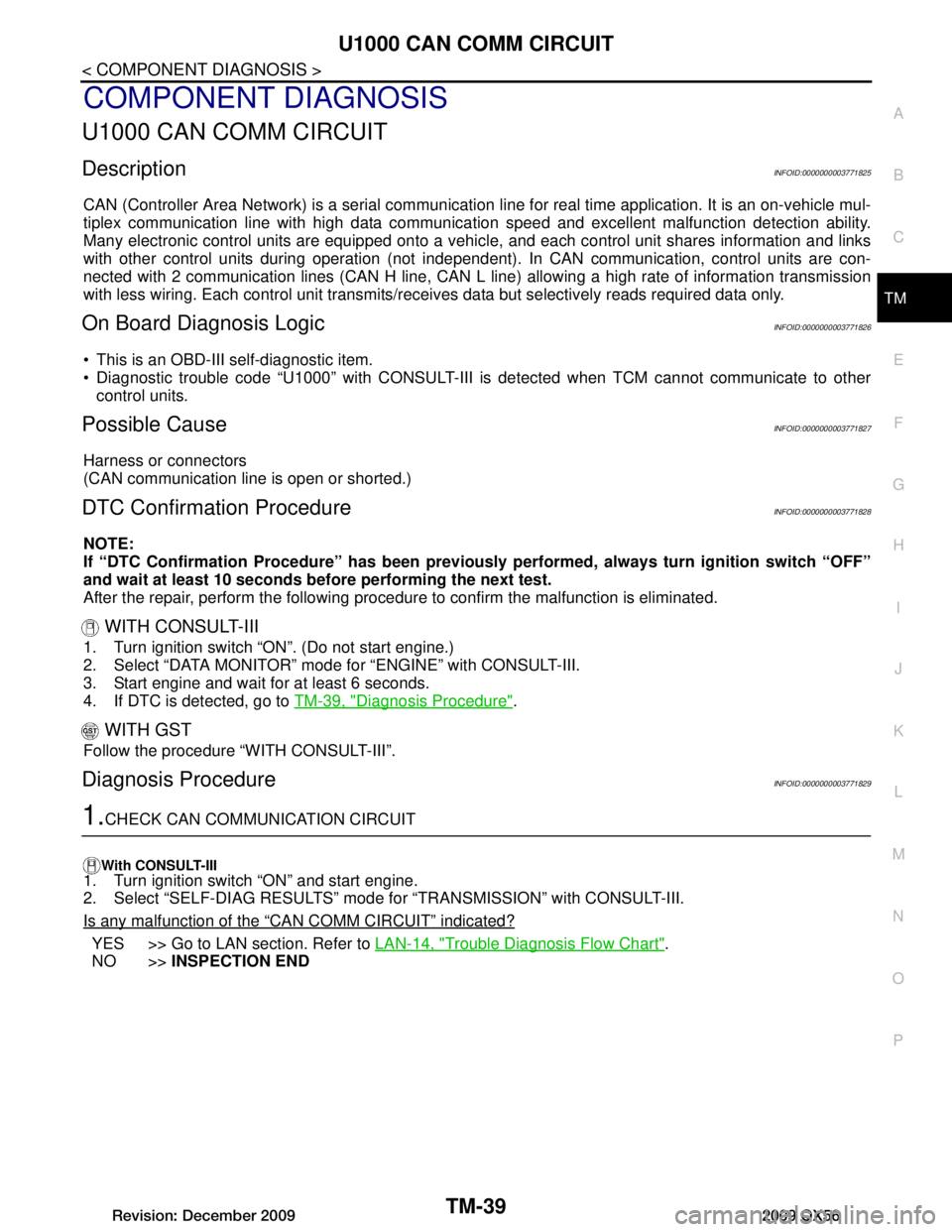
U1000 CAN COMM CIRCUIT
DescriptionINFOID:0000000003771825
CAN (Controller Area Network) is a serial communication li ne for real time application. It is an on-vehicle mul-
tiplex communication line with high data communica tion speed and excellent malfunction detection ability.
Many electronic control units are equipped onto a vehicl e, and each control unit shares information and links
with other control units during operation (not independent ). In CAN communication, control units are con-
nected with 2 communication lines (CAN H line, CAN L li ne) allowing a high rate of information transmission
with less wiring. Each control unit transmits/recei ves data but selectively reads required data only.
On Board Diagnosis LogicINFOID:0000000003771826
This is an OBD-III self-diagnostic item.
Diagnostic trouble code “U1000” with CONSULT-III is detected when TCM cannot communicate to other
control units.
Possible CauseINFOID:0000000003771827
Harness or connectors
(CAN communication line is open or shorted.)
DTC Confirmation ProcedureINFOID:0000000003771828
NOTE:
If “DTC Confirmation Procedure” has been previously performed, always turn ignition switch “OFF”
and wait at least 10 seconds before performing the next test.
After the repair, perform the following procedure to confirm the malfunction is eliminated.
WITH CONSULT-III
1. Turn ignition switch “ON”. (Do not start engine.)
2. Select “DATA MONITOR” mode for “ENGINE” with CONSULT-III.
3. Start engine and wait for at least 6 seconds.
4. If DTC is detected, go to TM-39, "Diagnosis Procedure"
.
WITH GST
Follow the procedure “WITH CONSULT-III”.
Diagnosis ProcedureINFOID:0000000003771829
1.CHECK CAN COMMUNICATION CIRCUIT
With CONSULT-III1. Turn ignition switch “ON” and start engine.
2. Select “SELF-DIAG RESULTS” mode for “TRANSMISSION” with CONSULT-III.
Is any malfunction of the
“CAN COMM CIRCUIT” indicated?
YES >> Go to LAN section. Refer to LAN-14, "Trouble Diagnosis Flow Chart".
NO >> INSPECTION END
Revision: December 20092009 QX56
Page 3688 of 4171

TM-40
< COMPONENT DIAGNOSIS >
P0615 STARTER RELAY
P0615 STARTER RELAY
DescriptionINFOID:0000000003771830
TCM prohibits cranking other than at “P” or “N” position.
CONSULT-III Reference Value in Data Monitor ModeINFOID:0000000003771831
On Board Diagnosis LogicINFOID:0000000003771832
This is not an OBD-II self-diagnostic item.
Diagnostic trouble code “P0615” with CONSULT-III is det ected when starter relay is switched “ON” other
than at “P” or “N” position. (Or when sw itched “OFF” at “P” or “N” position).
Possible CauseINFOID:0000000003771833
Harness or connectors
[The starter relay and TCM circuit is open or shorted.]
Starter relay
DTC Confirmation ProcedureINFOID:0000000003771834
NOTE:
If “DTC Confirmation Procedure” has been previously performed, always turn ignition switch “OFF”
and wait at least 10 seconds before performing the next test.
After the repair, perform the following proc edure to confirm the malfunction is eliminated.
WITH CONSULT-III
1. Turn ignition switch “ON”. (Do not start engine.)
2. Select “DATA MONITOR” mode for “TRANSMISSION” with CONSULT-III.
3. Start engine.
4. Drive vehicle for at least 2 consecutive seconds.
5. If DTC is detected, go to TM-40, "Diagnosis Procedure"
.
Diagnosis ProcedureINFOID:0000000003771835
1.CHECK STARTER RELAY
With CONSULT-III
1. Turn ignition switch “ON”. (Do not start engine.)
2. Select “SELECTION FROM MENU” in “DATA MONI TOR” mode for “TRANSMISSION” with CONSULT-III
and check monitor “STARTER RELAY” ON/OFF.
Without CONSULT-III
Item name Condition Display value
STARTER RELAY Selector lever in “N”,“P” position. ON
Selector lever in other position. OFF
Item name Condition Display value
STARTER RELAY Selector lever in "N'', "P'' positions. ON
Selector lever in other positions. OFF
Revision: December 20092009 QX56
Page 3691 of 4171
P0700 TRANSMISSION CONTROLTM-43
< COMPONENT DIAGNOSIS >
CEF
G H
I
J
K L
M A
B
TM
N
O P
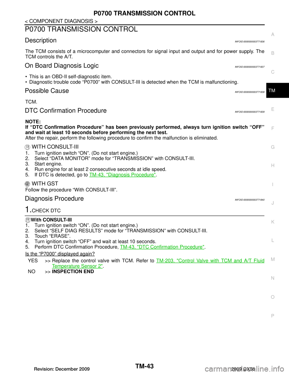
P0700 TRANSMISSION CONTROL
DescriptionINFOID:0000000003771836
The TCM consists of a microcomputer and connectors for signal input and output and for power supply. The
TCM controls the A/T.
On Board Diagnosis LogicINFOID:0000000003771837
This is an OBD-II self-diagnostic item.
Diagnostic trouble code “P0700” with CONSULT-III is detected when the TCM is malfunctioning.
Possible CauseINFOID:0000000003771838
TCM.
DTC Confirmation ProcedureINFOID:0000000003771839
NOTE:
If “DTC Confirmation Procedure” has been previously performed, always turn ignition switch “OFF”
and wait at least 10 seconds before performing the next test.
After the repair, perform the following procedure to confirm the malfunction is eliminated.
WITH CONSULT-III
1. Turn ignition switch “ON”. (Do not start engine.)
2. Select “DATA MONITOR” mode for “TRANSMISSION” with CONSULT-III.
3. Start engine.
4. Run engine for at least 2 cons ecutive seconds at idle speed.
5. If DTC is detected, go to TM-43, "Diagnosis Procedure"
.
WITH GST
Follow the procedure “With CONSULT-III”.
Diagnosis ProcedureINFOID:0000000003771840
1.CHECK DTC
With CONSULT-III
1. Turn ignition switch “ON”. (Do not start engine.)
2. Select “SELF DIAG RESULTS” mode fo r “TRANSMISSION” with CONSULT-III.
3. Touch “ERASE”.
4. Turn ignition switch “OFF” and wait at least 10 seconds.
5. Perform DTC Confirmation Procedure, TM-43, "DTC Confirmation Procedure"
.
Is the
“P7000” displayed again?
YES >> Replace the control valve with TCM. Refer to TM-203, "Control Valve with TCM and A/T Fluid
Temperature Sensor 2".
NO >> INSPECTION END
Revision: December 20092009 QX56
Page 3692 of 4171

TM-44
< COMPONENT DIAGNOSIS >
P0705 TRANSMISSION RANGE SWITCH A
P0705 TRANSMISSION RANGE SWITCH A
DescriptionINFOID:0000000003771841
The transmission range switch detects the selector lever position and sends a signal to the TCM.
CONSULT-III Reference Value in Data Monitor ModeINFOID:0000000003771842
On Board Diagnosis LogicINFOID:0000000003771843
This is an OBD-II self-diagnostic item.
Diagnostic trouble code “P0705” with CONSULT-III is detected under the following conditions.
- When TCM does not receive the correct voltage signal fr om the transmission range switch 1, 2, 3, 4 based
on the gear position.
- When no other position but “P” positi on is detected from “N” positions.
Possible CauseINFOID:0000000003771844
Harness or connectors
[The transmission range switch 1, 2, 3, 4 and TCM circuit is open or shorted.]
Transmission range s witch 1, 2, 3, 4
DTC Confirmation ProcedureINFOID:0000000003771845
CAUTION:
Always drive vehicle at a safe speed.
NOTE:
If “DTC Confirmation Procedure” has been previously performed, always turn ignition switch “OFF”
and wait at least 10 seconds before performing the next test.
After the repair, perform the following proc edure to confirm the malfunction is eliminated.
WITH CONSULT-III
1. Turn ignition switch “ON”. (Do not start engine.)
2. Select “DATA MONITOR” mode for “ENGINE” with CONSULT-III.
3. Start engine.
4. Drive vehicle and maintain the following conditions for at least 2 consecutive seconds.
THRTL POS SEN: More than 1.2V
5. If DTC is detected, go to TM-44, "Diagnosis Procedure"
.
WITH GST
Follow the procedure “With CONSULT-III”.
Diagnosis ProcedureINFOID:0000000003771846
1.CHECK TRANSMISSION RANGE SWITCH CIRCUIT
With CONSULT-III
1. Turn ignition switch “ON”. (Do not start engine.)
2. Select “SELECTION FROM MENU” in “DATA MONI TOR” mode for “TRANSMISSION” with CONSULT-III.
Item name Condition Display value
SLCTLVR POSI Selector lever in
“N”,“P” positions. N/P
Selector lever in “R” position. R
Selector lever in “D” position. D Selector lever in “4” position. 4
Selector lever in “3” position. 3
Selector lever in “2” position. 2
Selector lever in “1” position. 1
Revision: December 20092009 QX56
Page 3695 of 4171
P0717 INPUT SPEED SENSOR ATM-47
< COMPONENT DIAGNOSIS >
CEF
G H
I
J
K L
M A
B
TM
N
O P
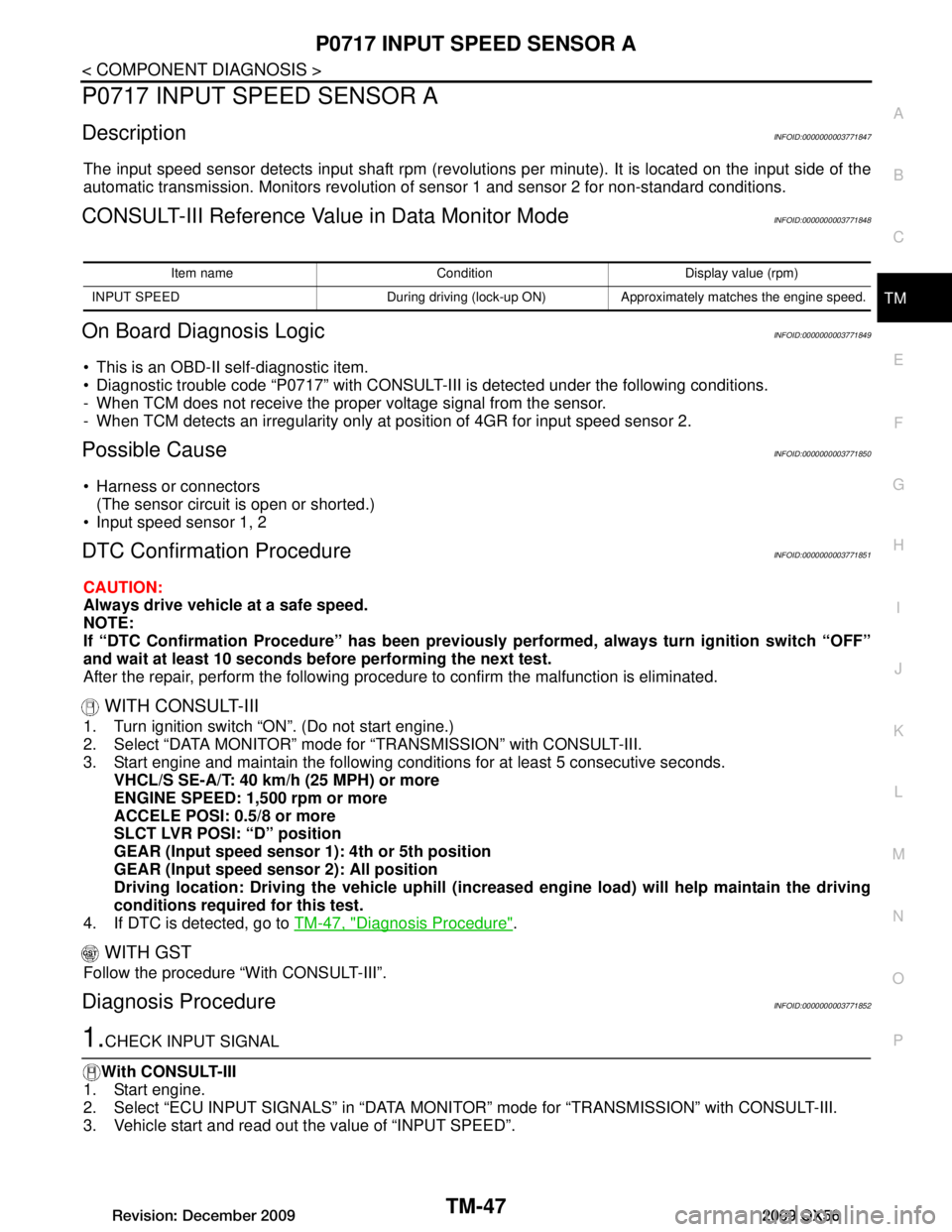
P0717 INPUT SPEED SENSOR A
DescriptionINFOID:0000000003771847
The input speed sensor detects input shaft rpm (revolutions per minute). It is located on the input side of the
automatic transmission. Monitors revolution of sensor 1 and sensor 2 for non-standard conditions.
CONSULT-III Reference Value in Data Monitor ModeINFOID:0000000003771848
On Board Diagnosis LogicINFOID:0000000003771849
This is an OBD-II self-diagnostic item.
Diagnostic trouble code “P0717” with CONSULT-III is detected under the following conditions.
- When TCM does not receive the proper voltage signal from the sensor.
- When TCM detects an irregularity only at pos ition of 4GR for input speed sensor 2.
Possible CauseINFOID:0000000003771850
Harness or connectors
(The sensor circuit is open or shorted.)
Input speed sensor 1, 2
DTC Confirmation ProcedureINFOID:0000000003771851
CAUTION:
Always drive vehicle at a safe speed.
NOTE:
If “DTC Confirmation Procedure” has been previously performed, always turn ignition switch “OFF”
and wait at least 10 seconds before performing the next test.
After the repair, perform the following procedure to confirm the malfunction is eliminated.
WITH CONSULT-III
1. Turn ignition switch “ON”. (Do not start engine.)
2. Select “DATA MONITOR” mode for “TRANSMISSION” with CONSULT-III.
3. Start engine and maintain the following conditions for at least 5 consecutive seconds. VHCL/S SE-A/T: 40 km/h (25 MPH) or more
ENGINE SPEED: 1,500 rpm or more
ACCELE POSI: 0.5/8 or more
SLCT LVR POSI: “D” position
GEAR (Input speed sensor 1): 4th or 5th position
GEAR (Input speed senso r 2): All position
Driving location: Driving the vehic le uphill (increased engine load) will help maintain the driving
conditions required for this test.
4. If DTC is detected, go to TM-47, "Diagnosis Procedure"
.
WITH GST
Follow the procedure “With CONSULT-III”.
Diagnosis ProcedureINFOID:0000000003771852
1.CHECK INPUT SIGNAL
With CONSULT-III
1. Start engine.
2. Select “ECU INPUT SIGNALS” in “DATA MONITO R” mode for “TRANSMISSION” with CONSULT-III.
3. Vehicle start and read out t he value of “INPUT SPEED”.
Item name Condition Display value (rpm)
INPUT SPEED During driving (lock-up ON) Approximately matches the engine speed.
Revision: December 20092009 QX56
Page 3697 of 4171
P0720 OUTPUT SPEED SENSORTM-49
< COMPONENT DIAGNOSIS >
CEF
G H
I
J
K L
M A
B
TM
N
O P
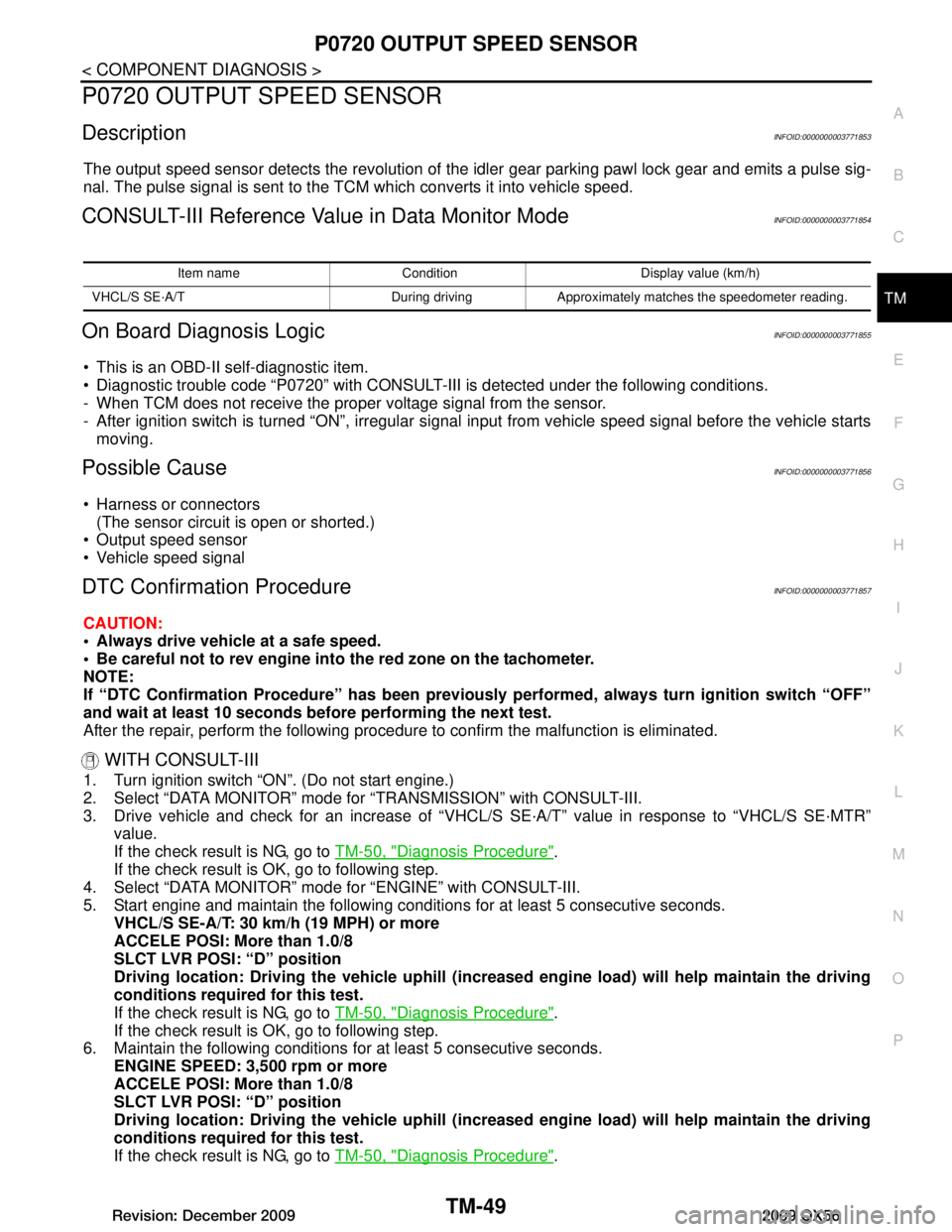
P0720 OUTPUT SPEED SENSOR
DescriptionINFOID:0000000003771853
The output speed sensor detects the revolution of the idler gear parking pawl lock gear and emits a pulse sig-
nal. The pulse signal is sent to the TC M which converts it into vehicle speed.
CONSULT-III Reference Value in Data Monitor ModeINFOID:0000000003771854
On Board Diagnosis LogicINFOID:0000000003771855
This is an OBD-II self-diagnostic item.
Diagnostic trouble code “P0720” with CONSULT-III is detected under the following conditions.
- When TCM does not receive the proper voltage signal from the sensor.
- After ignition switch is turned “ON”, irregular signal input from vehicle speed signal before the vehicle starts
moving.
Possible CauseINFOID:0000000003771856
Harness or connectors (The sensor circuit is open or shorted.)
Output speed sensor
Vehicle speed signal
DTC Confirmation ProcedureINFOID:0000000003771857
CAUTION:
Always drive vehicle at a safe speed.
Be careful not to rev engine into the red zone on the tachometer.
NOTE:
If “DTC Confirmation Procedure” has been previously performed, always turn ignition switch “OFF”
and wait at least 10 seconds before performing the next test.
After the repair, perform the following procedure to confirm the malfunction is eliminated.
WITH CONSULT-III
1. Turn ignition switch “ON”. (Do not start engine.)
2. Select “DATA MONITOR” mode for “TRANSMISSION” with CONSULT-III.
3. Drive vehicle and check for an increase of “VHCL/S SE·A/T” value in response to “VHCL/S SE·MTR”
value.
If the check result is NG, go to TM-50, "Diagnosis Procedure"
.
If the check result is OK, go to following step.
4. Select “DATA MONITOR” mode for “ENGINE” with CONSULT-III.
5. Start engine and maintain the following conditions for at least 5 consecutive seconds.
VHCL/S SE-A/T: 30 km/h (19 MPH) or more
ACCELE POSI: More than 1.0/8
SLCT LVR POSI: “D” position
Driving location: Driving the vehic le uphill (increased engine load) will help maintain the driving
conditions required for this test.
If the check result is NG, go to TM-50, "Diagnosis Procedure"
.
If the check result is OK, go to following step.
6. Maintain the following conditions for at least 5 consecutive seconds.
ENGINE SPEED: 3,500 rpm or more
ACCELE POSI: More than 1.0/8
SLCT LVR POSI: “D” position
Driving location: Driving the vehic le uphill (increased engine load) will help maintain the driving
conditions required for this test.
If the check result is NG, go to TM-50, "Diagnosis Procedure"
.
Item name Condition Display value (km/h)
VHCL/S SE·A/T During driving Approximately matches the speedometer reading.
Revision: December 20092009 QX56
Page 3700 of 4171
TM-52
< COMPONENT DIAGNOSIS >
P0725 ENGINE SPEED
P0725 ENGINE SPEED
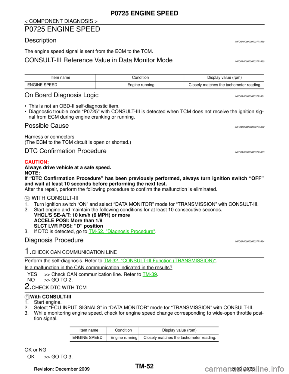
DescriptionINFOID:0000000003771859
The engine speed signal is sent from the ECM to the TCM.
CONSULT-III Reference Value in Data Monitor ModeINFOID:0000000003771860
On Board Diagnosis LogicINFOID:0000000003771861
This is not an OBD-II self-diagnostic item.
Diagnostic trouble code “P0725” with CONSULT-III is detected when TCM does not receive the ignition sig-
nal from ECM during engine cranking or running.
Possible CauseINFOID:0000000003771862
Harness or connectors
(The ECM to the TCM circuit is open or shorted.)
DTC Confirmation ProcedureINFOID:0000000003771863
CAUTION:
Always drive vehicle at a safe speed.
NOTE:
If “DTC Confirmation Procedure” has been previously performed, always turn ignition switch “OFF”
and wait at least 10 seconds before performing the next test.
After the repair, perform the following proc edure to confirm the malfunction is eliminated.
WITH CONSULT-III
1. Turn ignition switch “ON” and select “DATA MO NITOR” mode for “TRANSMISSION” with CONSULT-III.
2. Start engine and maintain the following conditions for at least 10 consecutive seconds. VHCL/S SE-A/T: 10 km/h (6 MPH) or more
ACCELE POSI: More than 1/8
SLCT LVR POSI: “D” position
3. If DTC is detected, go to TM-52, "Diagnosis Procedure"
.
Diagnosis ProcedureINFOID:0000000003771864
1.CHECK CAN COMMUNICATION LINE
Perform the self-diagnosis. Refer to TM-32, "CONSULT-III Function (TRANSMISSION)"
.
Is a malfunction in the CAN communication indicated in the results?
YES >> Check CAN communication line. Refer to TM-39.
NO >> GO TO 2.
2.CHECK DTC WITH TCM
With CONSULT-III
1. Start engine.
2. Select “ECU INPUT SIGNALS” in “DATA MONI TOR” mode for “TRANSMISSION” with CONSULT-III.
3. While monitoring engine speed, check for engine speed change corresponding to wide-open throttle posi-
tion signal.
OK or NG
OK >> GO TO 3.
Item name Condition Display value (rpm)
ENGINE SPEED Engine running Closely matches the tachometer reading.
Item name Condition Display value (rpm)
ENGINE SPEED Engine running Closel y matches the tachometer reading.
Revision: December 20092009 QX56
Page 3702 of 4171
TM-54
< COMPONENT DIAGNOSIS >
P0731 1GR INCORRECT RATIO
P0731 1GR INCORRECT RATIO
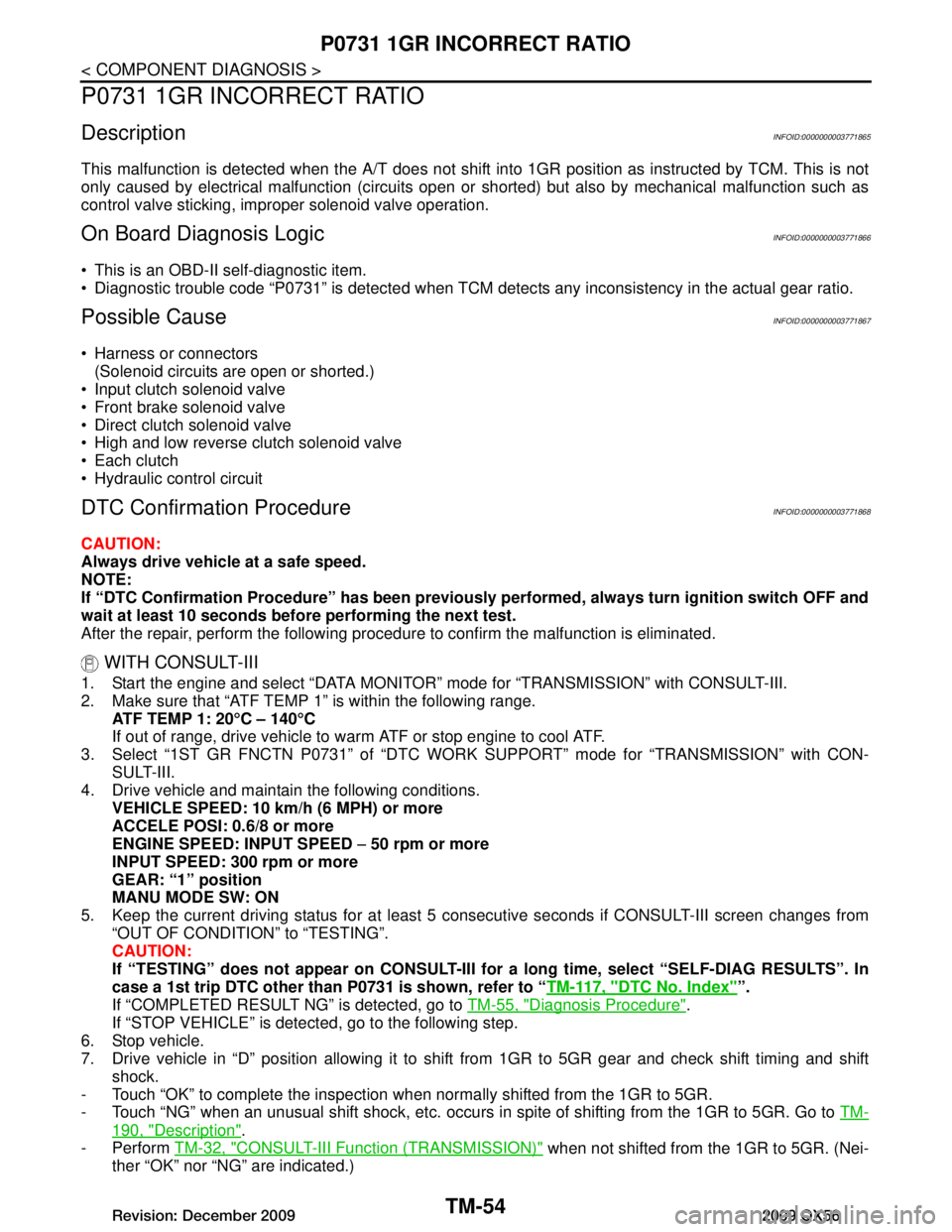
DescriptionINFOID:0000000003771865
This malfunction is detected when the A/T does not shift into 1GR position as instructed by TCM. This is not
only caused by electrical malfunction (circuits open or shorted) but also by mechanical malfunction such as
control valve sticking, improper solenoid valve operation.
On Board Diagn osis LogicINFOID:0000000003771866
This is an OBD-II self-diagnostic item.
Diagnostic trouble code “P0731” is detected when TCM detec ts any inconsistency in the actual gear ratio.
Possible CauseINFOID:0000000003771867
Harness or connectors
(Solenoid circuits are open or shorted.)
Input clutch solenoid valve
Front brake solenoid valve
Direct clutch solenoid valve
High and low reverse clutch solenoid valve
Each clutch
Hydraulic control circuit
DTC Confirmation ProcedureINFOID:0000000003771868
CAUTION:
Always drive vehicle at a safe speed.
NOTE:
If “DTC Confirmation Procedure” has been previously performed, alw ays turn ignition switch OFF and
wait at least 10 seconds before performing the next test.
After the repair, perform the following proc edure to confirm the malfunction is eliminated.
WITH CONSULT-III
1. Start the engine and select “DATA MONITOR” mode for “TRANSMISSION” with CONSULT-III.
2. Make sure that “ATF TEMP 1” is within the following range. ATF TEMP 1: 20 °C – 140 °C
If out of range, drive vehicle to warm ATF or stop engine to cool ATF.
3. Select “1ST GR FNCTN P0731” of “DTC WORK SUPPORT” mode for “TRANSMISSION” with CON-
SULT-III.
4. Drive vehicle and maintain the following conditions.
VEHICLE SPEED: 10 km/h (6 MPH) or more
ACCELE POSI: 0.6/8 or more
ENGINE SPEED: INPUT SPEED − 50 rpm or more
INPUT SPEED: 300 rpm or more
GEAR: “1” position
MANU MODE SW: ON
5. Keep the current driving status for at least 5 consecutive seconds if CONSULT-III screen changes from
“OUT OF CONDITION” to “TESTING”.
CAUTION:
If “TESTING” does not ap pear on CONSULT-III for a long ti me, select “SELF-DIAG RESULTS”. In
case a 1st trip DTC other than P0731 is shown, refer to “ TM-117, "DTC No. Index"
”.
If “COMPLETED RESULT NG” is detected, go to TM-55, "Diagnosis Procedure"
.
If “STOP VEHICLE” is detect ed, go to the following step.
6. Stop vehicle.
7. Drive vehicle in “D” position allowing it to shif t from 1GR to 5GR gear and check shift timing and shift
shock.
- Touch “OK” to complete the inspection when normally shifted from the 1GR to 5GR.
- Touch “NG” when an unusual shift shock, etc. occurs in spite of shifting from the 1GR to 5GR. Go to TM-
190, "Description".
- Perform TM-32, "CONSULT-III Function (TRANSMISSION)"
when not shifted from the 1GR to 5GR. (Nei-
ther “OK” nor “NG” are indicated.)
Revision: December 20092009 QX56