2009 INFINITI QX56 ECO mode
[x] Cancel search: ECO modePage 3945 of 4171

IN-CABIN MICROFILTERVTL-5
< FUNCTION DIAGNOSIS >
C
DE
F
G H
J
K L
M A
B
VTL
N
O P
FUNCTION DIAGNOSIS
IN-CABIN MICROFILTER
DescriptionINFOID:0000000003775259
FUNCTION
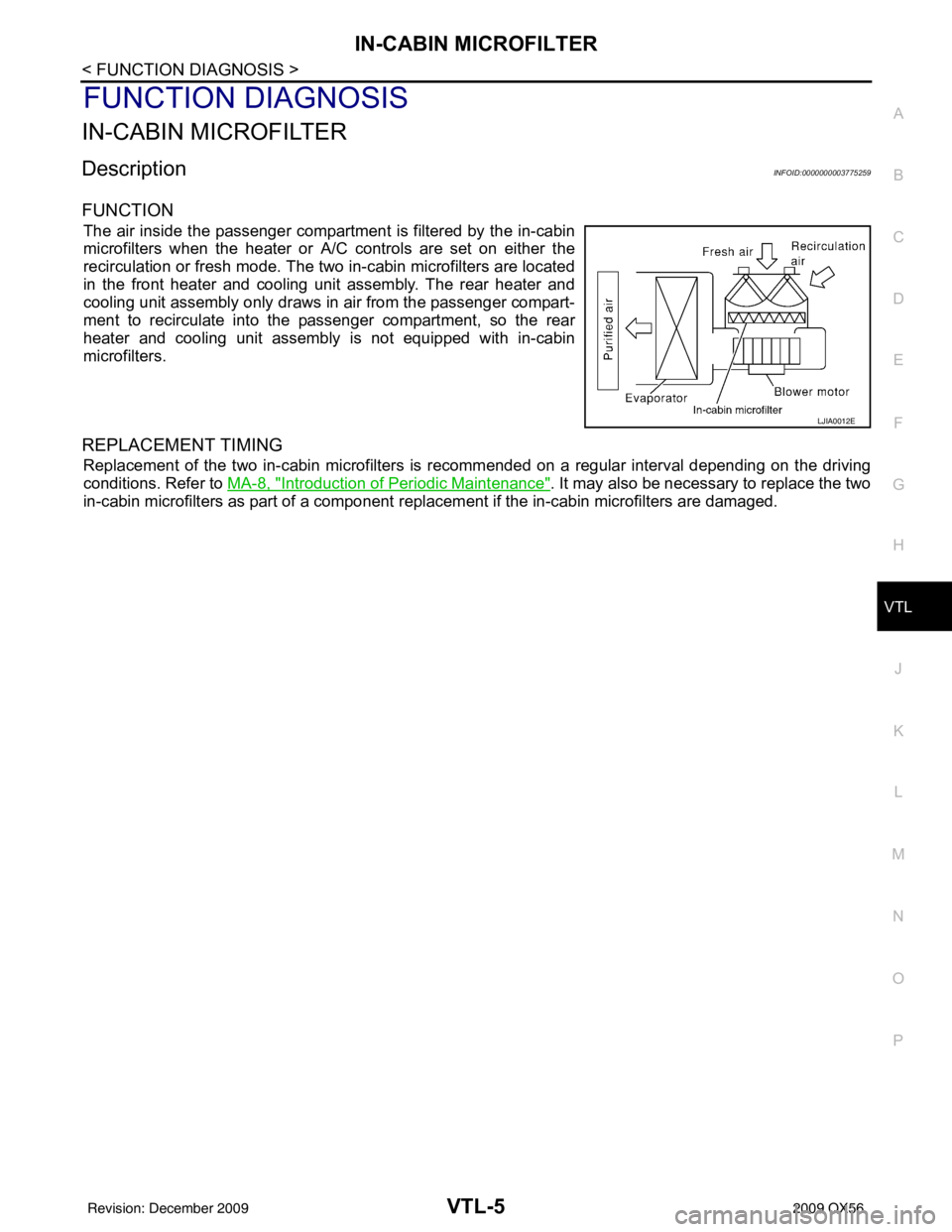
The air inside the passenger compartment is filtered by the in-cabin
microfilters when the heater or A/C controls are set on either the
recirculation or fresh mode. The two in-cabin microfilters are located
in the front heater and cooling unit assembly. The rear heater and
cooling unit assembly only draws in air from the passenger compart-
ment to recirculate into the passenger compartment, so the rear
heater and cooling unit assembly is not equipped with in-cabin
microfilters.
REPLACEMENT TIMING
Replacement of the two in-cabin microfilters is recommended on a regular interval depending on the driving
conditions. Refer to MA-8, "
Introduction of Periodic Maintenance". It may also be necessary to replace the two
in-cabin microfilters as part of a component r eplacement if the in-cabin microfilters are damaged.
LJIA0012E
Revision: December 20092009 QX56
Page 4024 of 4171

WCS
COMBINATION METERWCS-47
< ECU DIAGNOSIS >
C
DE
F
G H
I
J
K L
M B A
O P
DTC IndexINFOID:0000000004115463
Function Specifications
Speedometer
Zero indication.
Tachometer
Fuel gauge
Engine coolant temperature gauge
Engine oil pressure gauge
Voltage gauge
A/T oil temperature gauge
Illumination control
Meter illumination Change to nighttime mode when communication is lost.
Segment LCD Odometer
Freeze current indication.
A/T position Display turns off.
Buzzer Buzzer turns off.
Warning lamp/indicator lamp ABS warning lamp
Lamp turns on when communication is lost.
Brake warning lamp
VDC OFF indicator lamp
SLIP indicator lamp
A/T CHECK warning lamp
Lamp turns off when communication is lost.
Oil pressure/coolant temperature
warning lamp
Light indicator
Malfunction indicator lamp
Master warning lamp
Air bag warning lamp
High beam indicator
Turn signal indicator lamp
CRUISE indicator lamp
Driver and passenger seat belt warn-
ing lamp
Lamp turns off when disconnected.
Charge warning lamp
Security indicator lamp
4WD indicator lamp
ATP indicator lamp
CK SUSP warning lamp
Low tire pressu
re warning lamp Lamp will flash every second for 1 minute and then stay on con-
tinuously thereafter.
CONSULT-III display
MalfunctionReference
page
CAN COMM CIRC
[U1000] Malfunction is detected in CAN communication.
CAUTION:
Even when there is no ma
lfunction on CAN communication system, malfunction may be
misinterpreted when battery has low voltag e (when maintaining 7 - 8 V for about 2 sec-
onds) or 10A fuse [No. 19, located in the fuse block (J/B)] is disconnected. MWI-28
VEHICLE SPEED
CIRC
[B2205]Malfunction is detected when an erroneous speed signal is input.
CAUTION:
Even when there is no malfunction on speed signal system, malfunction may be misin-
terpreted when battery has low voltage (whe
n maintaining 7 - 8 V for about 2 seconds). MWI-29
Revision: December 20092009 QX56
Page 4053 of 4171

DIAGNOSIS SYSTEM (BCM)WT-11
< FUNCTION DIAGNOSIS >
C
DF
G H
I
J
K L
M A
B
WT
N
O P
DIAGNOSIS SYSTEM (BCM)
CONSULT-III Function (BCM)INFOID:0000000003772370
CONSULT-III DIAGNOSTIC MODES
CONSULT-III can display each diagnostic item using the diagnostic test modes shown following.
DESCRIPTION
During driving, the tire pressure monitoring system receives the signal transmitted from the transmitter
installed in each wheel, and turns on the low tire pressure warning lamp when the tire pressure becomes low.
The control unit (BCM) for this system has pr essure judgement and self-diagnosis functions.
FUNCTION
When the tire pressure monitoring system detects low infl ation pressure or an internal malfunction, the low tire
pressure warning lamp in the combination meter comes on. The malfunction is indicated by the low tire pres-
sure warning lamp flashing.
CONSULT-III Application to Ti re Pressure Monitoring System
× : Applicable
– : Not applicable
Data Monitor Mode
Diagnostic mode Description
WORK SUPPORT Supports inspections and adjustments. Commands are transmitted to the BCM
for setting the status suitable for required operation, input/output signals are re-
ceived from the BCM and received data is displayed.
DATA MONITOR Displays BCM input/output data in real time.
ACTIVE TEST Operation of electrical loads can be checked by sending drive signal to them.
SELF-DIAG RESULTS Displays BCM self-diagnosis results.
CAN DIAG SUPPORT MNTR The result of transmit/receive diagnosis of CAN communication can be read.
ECU PART NUMBER BCM part number can be read.
CONFIGURATION Performs BCM configuration read/write functions.
ITEMSELF-DIAGNOSTIC RESULTS DATA MONITOR
Front - Left transmitter ××
Front - Right transmitter ××
Rear - Left transmitter ××
Rear - Right transmitter ××
Warning lamp —×
Vehicle speed ××
CAN Communication ××
MONITORCONDITION SPECIFICATION
VHCL SPEED Drive vehicle. Vehicle speed (km/h or MPH)
AIR PRESS FL
AIR PRESS FR
AIR PRESS RR
AIR PRESS RL • Drive vehicle for a few minutes.
Tire pressure (kPa or psi)
or
• Ignition switch ON and activation tool is transmitting activation signals.
Revision: December 20092009 QX56
Page 4054 of 4171

WT-12
< FUNCTION DIAGNOSIS >
DIAGNOSIS SYSTEM (BCM)
NOTE:
Before performing the self-diagnosis, be sure to register the ID, or the actual malfunction location may be different from that displayed on
CONSULT-III.
Self-Diagnosis (With CONSULT-III)INFOID:0000000003772371
DESCRIPTION
During driving, the tire pressure monitoring system receives the signal trans mitted from the transmitter
installed in each wheel, and turns on the low tire pressure warning lamp when the tire pressure becomes low.
The control unit (BCM) for this system has pressure judgement and self-diagnosis functions.
FUNCTION
When the tire pressure monitoring system detects low inflation pressure or an internal malfunction, the low tire
pressure warning lamp in the combination meter comes on. The malfunction is indicated by the low tire pres-
sure warning lamp flashing.
CONSULT-III Application to Tire Pressure Monitoring System
× : Applicable
– : Not applicable
Data Monitor Mode
NOTE:
Before performing the self-diagnosis, be sure to register the ID, or the actual malfunction location may be different from that displayed on
CONSULT-III. ID REGST FL1
ID REGST FR1
ID REGST RR1
ID REGST RL1
Ignition switch ON ID not registered: YET
ID registered: DONE
WARNING LAMP Low tire pressure
warning lamp on: ON
Low tire pressure warning lamp off: OFF
MONITOR
CONDITION SPECIFICATION
ITEMSELF-DIAGNOSTIC RESULTS DATA MONITOR
Front - Left transmitter ××
Front - Right transmitter ××
Rear - Left transmitter ××
Rear - Right transmitter ××
Warning lamp —×
Vehicle speed ××
CAN Communication ××
MONITORCONDITION SPECIFICATION
VHCL SPEED Drive vehicle. Vehicle speed (km/h or MPH)
AIR PRESS FL
AIR PRESS FR
AIR PRESS RR
AIR PRESS RL • Drive vehicle for a few minutes.
Tire pressure (kPa or psi)
or
• Ignition switch ON and activation tool is transmitting activation signals.
ID REGST FL1
ID REGST FR1
ID REGST RR1
ID REGST RL1 Ignition switch ON ID not registered: YET
ID registered: DONE
WARNING LAMP Low tire pressure
warning lamp on: ON
Low tire pressure warning lamp off: OFF
Revision: December 20092009 QX56
Page 4079 of 4171

PRECAUTIONSWT-37
< PRECAUTION >
C
DF
G H
I
J
K L
M A
B
WT
N
O P
PRECAUTION
PRECAUTIONS
Precaution for Supplemental Restraint System (SRS) "AIR BAG" and "SEAT BELT
PRE-TENSIONER"
INFOID:0000000005873220
The Supplemental Restraint System such as “AIR BAG” and “SEAT BELT PRE-TENSIONER”, used along
with a front seat belt, helps to reduce the risk or severi ty of injury to the driver and front passenger for certain
types of collision. This system includes seat belt switch inputs and dual stage front air bag modules. The SRS
system uses the seat belt switches to determine the front air bag deployment, and may only deploy one front
air bag, depending on the severity of a collision and w hether the front occupants are belted or unbelted.
Information necessary to service the system safely is included in the SR and SB section of this Service Man-
ual.
WARNING:
• To avoid rendering the SRS inoper ative, which could increase the risk of personal injury or death in
the event of a collision which would result in air bag inflation, all maintenance must be performed by
an authorized NISSAN/INFINITI dealer.
• Improper maintenance, including in correct removal and installation of the SRS, can lead to personal
injury caused by unintentional act ivation of the system. For removal of Spiral Cable and Air Bag
Module, see the SR section.
• Do not use electrical test equipm ent on any circuit related to the SRS unless instructed to in this
Service Manual. SRS wiring harnesses can be identi fied by yellow and/or orange harnesses or har-
ness connectors.
PRECAUTIONS WHEN USING POWER TOOLS (AIR OR ELECTRIC) AND HAMMERS
WARNING:
• When working near the Airbag Diagnosis Sensor Un it or other Airbag System sensors with the Igni-
tion ON or engine running, DO NOT use air or el ectric power tools or strike near the sensor(s) with a
hammer. Heavy vibration could activate the sensor( s) and deploy the air bag(s), possibly causing
serious injury.
• When using air or electric power tools or hammers, always switch the Ignition OFF, disconnect the battery, and wait at least 3 minutes before performing any service.
Precaution Necessary for Steering Wheel Rotation After Battery Disconnect
INFOID:0000000005873221
NOTE:
• This Procedure is applied only to models with Intelligent Key system and NATS (NISSAN ANTI-THEFT SYS-
TEM).
• Remove and install all control units after disconnecti ng both battery cables with the ignition knob in the
″ LOCK ″ position.
• Always use CONSULT-III to perform self-diagnosis as a part of each function inspection after finishing work.
If DTC is detected, perform trouble diagnosis according to self-diagnostic results.
For models equipped with the Intelligent Key system and NATS , an electrically controlled steering lock mech-
anism is adopted on the key cylinder.
For this reason, if the battery is disconnected or if the battery is discharged, the steering wheel will lock and
steering wheel rotation will become impossible.
If steering wheel rotation is required when battery power is interrupted, follow the procedure below before
starting the repair operation.
OPERATION PROCEDURE
1. Connect both battery cables. NOTE:
Supply power using jumper cables if battery is discharged.
2. Use the Intelligent Key or mechanical key to turn the ignition switch to the ″ACC ″ position. At this time, the
steering lock will be released.
3. Disconnect both battery cables. The steering lock will remain released and the steering wheel can be
rotated.
4. Perform the necessary repair operation.
Revision: December 20092009 QX56
Page 4100 of 4171

DIAGNOSIS SYSTEM (IPDM E/R)WW-13
< FUNCTION DIAGNOSIS >
C
DE
F
G H
I
J
K
M A
B
WW
N
O P
DIAGNOSIS SYSTEM (IPDM E/R)
Diagnosis DescriptionINFOID:0000000004115472
AUTO ACTIVE TEST
Description
In auto active test mode, the IPDM E/R sends a drive signal to the following systems to check their operation.
• Oil pressure low/coolant pressure high warning indicator
• Oil pressure gauge
• Rear window defogger
• Front wipers
• Tail, license and parking lamps
• Front fog lamps
• Headlamps (Hi, Lo)
• A/C compressor (magnetic clutch)
• Cooling fan
Operation Procedure
1. Close the hood and front door RH, and lift the wiper arms from the windshield (to prevent windshield dam-
age due to wiper operation).
NOTE:
When auto active test is performed with hood opened, sprinkle water on windshield before hand.
2. Turn ignition switch OFF.
3. Turn the ignition switch ON and, within 20 seconds, press the front door switch LH 10 times. Then turn the ignition switch OFF.
4. Turn the ignition switch ON within 10 seconds. Af ter that the horn sounds once and the auto active test
starts.
5. After a series of the following operations is repeated 3 times, auto active test is completed.
NOTE:
When auto active test mode has to be cancelled halfway through test, turn ignition switch OFF.
CAUTION:
• If auto active test mode cannot be actua ted, check door switch system. Refer to DLK-71,
"ComponentFunctionCheck".
• Do not start the engine.
Inspection in Auto Active Test Mode
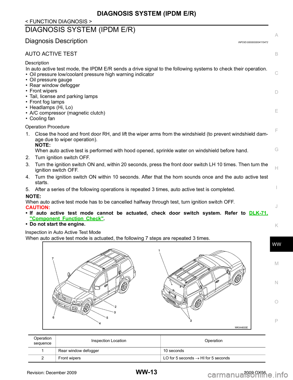
When auto active test mode is actuated, the following 7 steps are repeated 3 times.
Operation
sequence Inspection Location
Operation
1 Rear window defogger 10 seconds
2 Front wipers LO for 5 seconds → HI for 5 seconds
WKIA4655E
Revision: December 20092009 QX56
Page 4101 of 4171

WW-14
< FUNCTION DIAGNOSIS >
DIAGNOSIS SYSTEM (IPDM E/R)
Concept of auto active test
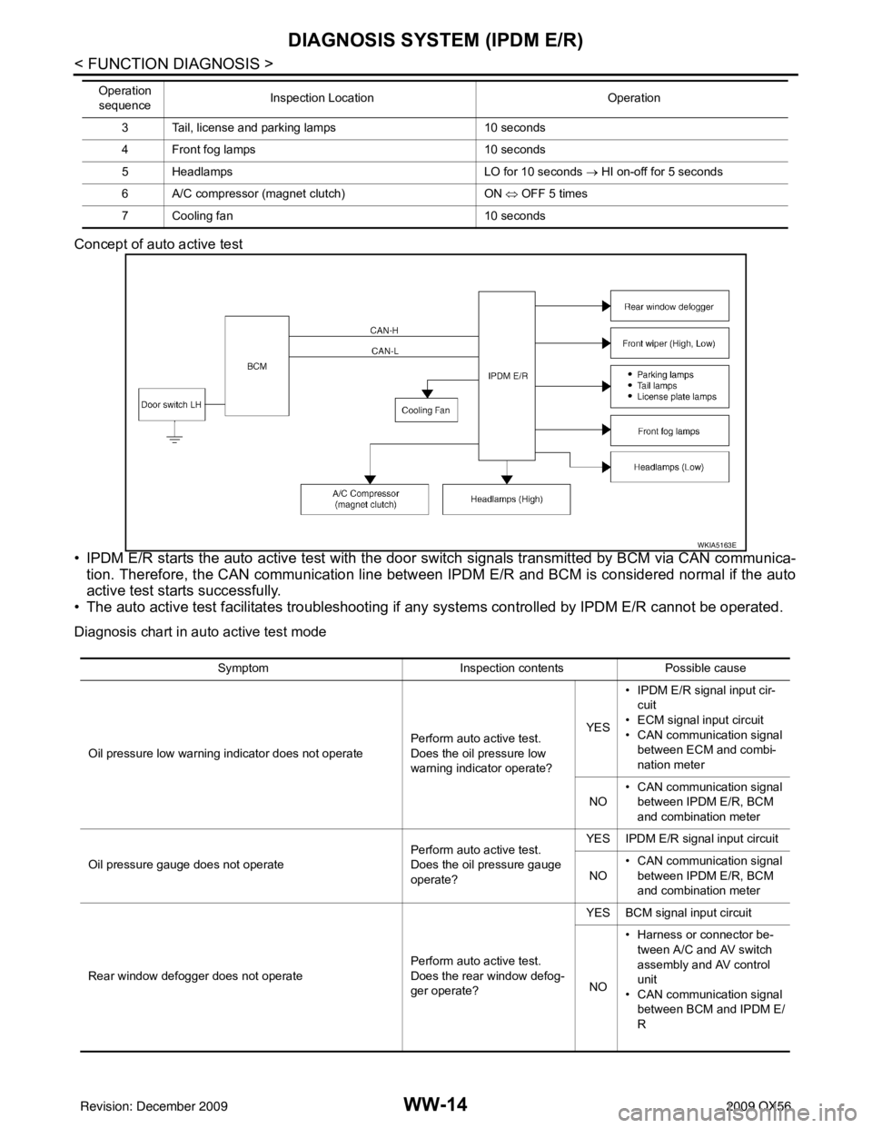
• IPDM E/R starts the auto active test with the door switch signals transmitted by BCM via CAN communica-
tion. Therefore, the CAN communication line between IPDM E/R and BCM is considered normal if the auto
active test starts successfully.
• The auto active test facilitates troubleshooting if any systems controlled by IPDM E/R cannot be operated.
Diagnosis chart in auto active test mode
3 Tail, license and parking lamps 10 seconds
4 Front fog lamps 10 seconds
5 Headlamps LO for 10 seconds → HI on-off for 5 seconds
6 A/C compressor (magnet clutch) ON ⇔ OFF 5 times
7 Cooling fan 10 seconds
Operation
sequence Inspection Location
Operation
WKIA5163E
SymptomInspection contentsPossible cause
Oil pressure low warning indicator does not operate Perform auto active test.
Does the oil pressure low
warning indicator operate?YES
• IPDM E/R signal input cir-
cuit
• ECM signal input circuit
• CAN communication signal between ECM and combi-
nation meter
NO • CAN communication signal
between IPDM E/R, BCM
and combination meter
Oil pressure gauge does not operate Perform auto active test.
Does the oil pressure gauge
operate?YES IPDM E/R signal input circuit
NO • CAN communication signal
between IPDM E/R, BCM
and combination meter
Rear window defogger does not operate Perform auto active test.
Does the rear window defog-
ger operate?YES BCM signal input circuit
NO • Harness or connector be-
tween A/C and AV switch
assembly and AV control
unit
• CAN communication signal between BCM and IPDM E/
R
Revision: December 20092009 QX56
Page 4152 of 4171

IPDM E/R (INTELLIGENT POWER DISTRIBUTION MODULE ENGINE ROOM)
WW-65
< ECU DIAGNOSIS >
C
D E
F
G H
I
J
K
M A
B
WW
N
O P
If No CAN Communication Is Available With BCM
IGNITION RELAY MALFUNCTION DETECTION FUNCTION
• IPDM E/R monitors the voltage at the contact circuit and excitation coil circuit of the ignition relay inside it.
• IPDM E/R judges the ignition relay error if the voltage differs between the contact circuit and the excitation
coil circuit.
• If the ignition relay cannot turn OFF due to contact seizure, it activates the tail lamp relay for 10 minutes to alert the user to the ignition relay malfunction when the ignition switch is turned OFF.
NOTE:
The tail lamp turns OFF when the ignition switch is turned ON.
FRONT WIPER CONTROL
IPDM E/R detects front wiper stop posit ion by a front wiper auto stop signal.
When a front wiper auto stop signal is in the conditions listed below, IPDM E/R stops power supply to wiper
after repeating a front wiper 10 second activation and 20 second stop five times.
NOTE:
This operation status can be confirmed on the IPDM E/R “DATA MONITOR” that displays “Block” for the item
“WIP PROT” while the wiper is stopped.
STARTER MOTOR PROTECTION FUNCTION
IPDM E/R turns OFF the starter control relay to protect the starter motor when the starter control relay remains
active for 90 seconds.
Control part Fail-safe in operation
Cooling fan • Turns ON the cooling fan relay when the ignition switch is turned ON
• Turns OFF the cooling fan relay when the ignition switch is turned OFF
Control part
Fail-safe in operation
Headlamp • Turns ON the headlamp low relay when the ignition switch is turned ON
• Turns OFF the headlamp low relay when the ignition switch is turned OFF
• Headlamp high relay OFF
•Parking lamps
• License plate lamps
• Tail lamps • Turns ON the tail lamp relay when the ignition switch is turned ON
• Turns OFF the tail lamp relay when the ignition switch is turned OFF
Front wiper • The status just before activation of fail-safe control is maintained until the ignition
switch is turned OFF while the front wiper is operating at LO or HI speed.
• The wiper is operated at LO speed until the ignition switch is turned OFF if the fail- safe control is activated while the front wipe r is set in the INT mode and the front wiper
motor is operating.
Rear window defogger Rear window defogger relay OFF
A/C compressor A/C relay OFF
Front fog lamps Front fog lamp relay OFF
Ignition switch Ignition relayTail lamp relay
ON ON —
OFF OFF —
Ignition switchFront wiper switch Auto stop signal
ON OFF
Front wiper stop position signal cannot be
input 10 seconds.
ON The signal does not change for 10 seconds.
Revision: December 20092009 QX56