2009 INFINITI QX56 Abs
[x] Cancel search: AbsPage 3409 of 4171
![INFINITI QX56 2009 Factory Service Manual IPDM E/R (INTELLIGENT POWER DISTRIBUTION MODULE ENGINE ROOM)
SEC-99
< ECU DIAGNOSIS > [WITH INTELLIGENT KEY SYSTEM]
C
D
E
F
G H
I
J
L
M A
B
SEC
N
O P
Te r m i n a l Wire
color Signal name Signal
inpu INFINITI QX56 2009 Factory Service Manual IPDM E/R (INTELLIGENT POWER DISTRIBUTION MODULE ENGINE ROOM)
SEC-99
< ECU DIAGNOSIS > [WITH INTELLIGENT KEY SYSTEM]
C
D
E
F
G H
I
J
L
M A
B
SEC
N
O P
Te r m i n a l Wire
color Signal name Signal
inpu](/manual-img/42/57031/w960_57031-3408.png)
IPDM E/R (INTELLIGENT POWER DISTRIBUTION MODULE ENGINE ROOM)
SEC-99
< ECU DIAGNOSIS > [WITH INTELLIGENT KEY SYSTEM]
C
D
E
F
G H
I
J
L
M A
B
SEC
N
O P
Te r m i n a l Wire
color Signal name Signal
input/
output Measuring condition
Reference value(Approx.)
Igni-
tion
switch Operation or condition
1 B/Y Battery power supply Input OFF —Battery voltage
2 R Battery power supply Input OFF —Battery voltage
3BRECM relay Output— Ignition switch ON or START
Battery voltage
Ignition switch OFF or ACC 0V
4W/LECM relay Output— Ignition switch ON or START
Battery voltage
Ignition switch OFF or ACC 0V
6L Throttle control motor
relay Output —Ignition switch ON or START
Battery voltage
Ignition switch OFF or ACC 0V
7 W/B ECM relay control Input — Ignition switch ON or START
0V
Ignition switch OFF or ACC Battery voltage
8 R/B Fuse 54 Output —Ignition switch ON or START
Battery voltage
Ignition switch OFF or ACC 0V
10 G Fuse 45 Output ONDaytime light system active
0V
Daytime light system inactive Battery voltage
11 Y/B A/C compressor Output ON or
START A/C switch ON or defrost A/C
switch
Battery voltage
A/C switch OFF or defrost A/C
switch 0V
12 L/W Ignition switch sup-
plied power Input —OFF or ACC
0V
ON or START Battery voltage
13 B/Y Fuel pump relay Output — Ignition switch ON or START
Battery voltage
Ignition switch OFF or ACC 0V
14 Y/R Fuse 49 Output —Ignition switch ON or START
Battery voltage
Ignition switch OFF or ACC 0V
15 LG/B Fuse 50 (VDC) Output — Ignition switch ON or START
Battery voltage
Ignition switch OFF or ACC 0V
15 GR Fuse 50 (ABS) Output — Ignition switch ON or START
Battery voltage
Ignition switch OFF or ACC 0V
16 G Fuse 51 Output —Ignition switch ON or START
Battery voltage
Ignition switch OFF or ACC 0V
17 W Fuse 55 Output —Ignition switch ON or START
Battery voltage
Ignition switch OFF or ACC 0V
19 W/R Starter motor Output START—Battery voltage
21 BR Ignition switch sup-
plied power
Input —OFF or ACC
0V
START Battery voltage
22 G Battery power supply Output OFF —Battery voltage
23 GR/W Door mirror defogger
output signal Output —When rear defogger switch is
ON
Battery voltage
When raker defogger switch is
OFF 0V
Revision: December 20092009 QX56
Page 3480 of 4171
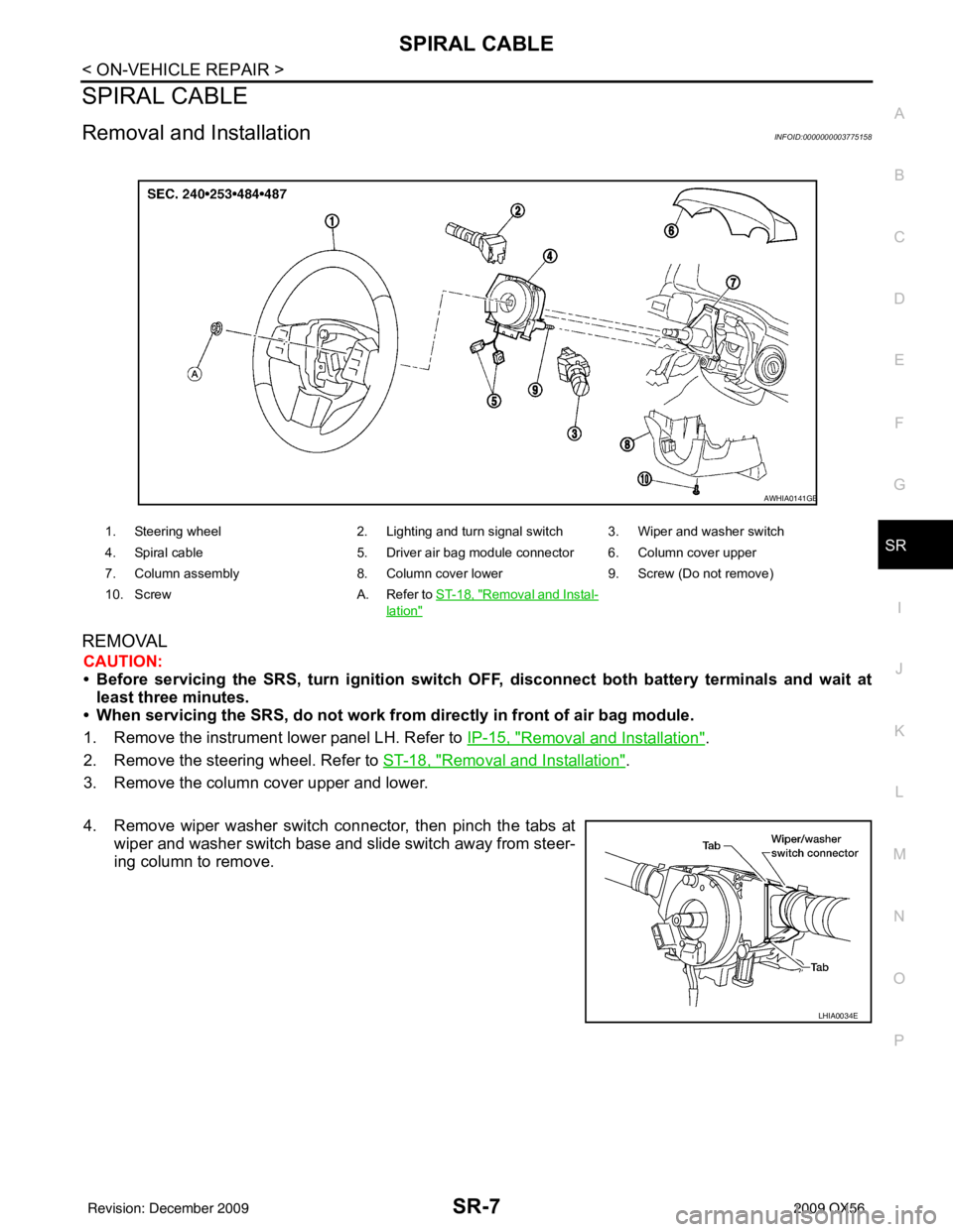
SPIRAL CABLESR-7
< ON-VEHICLE REPAIR >
C
DE
F
G
I
J
K L
M A
B
SR
N
O P
SPIRAL CABLE
Removal and InstallationINFOID:0000000003775158
REMOVAL
CAUTION:
• Before servicing the SRS, turn ignition switch OFF, disconnect both battery terminals and wait at
least three minutes.
• When servicing the SRS, do not work from directly in front of air bag module.
1. Remove the instrument lower panel LH. Refer to IP-15, "
Removal and Installation".
2. Remove the steering wheel. Refer to ST-18, "
Removal and Installation".
3. Remove the column cover upper and lower.
4. Remove wiper washer switch connector, then pinch the tabs at wiper and washer switch base and slide switch away from steer-
ing column to remove.
1. Steering wheel 2. Lighting and turn signal switch 3. Wiper and washer switch
4. Spiral cable 5. Driver air bag module connector 6. Column cover upper
7. Column assembly 8. Column cover lower9. Screw (Do not remove)
10. Screw A. Refer to ST-18, "
Removal and Instal-
lation"
AWHIA0141GB
LHIA0034E
Revision: December 20092009 QX56
Page 3481 of 4171
SR-8
< ON-VEHICLE REPAIR >
SPIRAL CABLE
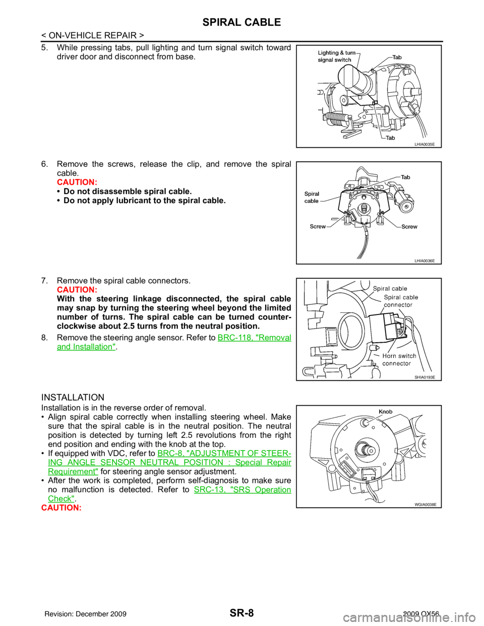
5. While pressing tabs, pull lighting and turn signal switch towarddriver door and disconnect from base.
6. Remove the screws, release the clip, and remove the spiral cable.
CAUTION:
• Do not disassemble spiral cable.
• Do not apply lubricant to the spiral cable.
7. Remove the spiral cable connectors. CAUTION:
With the steering linkage di sconnected, the spiral cable
may snap by turning the steer ing wheel beyond the limited
number of turns. The spiral cable can be turned counter-
clockwise about 2.5 turns fr om the neutral position.
8. Remove the steering angle sensor. Refer to BRC-118, "
Removal
and Installation".
INSTALLATION
Installation is in the reverse order of removal.
• Align spiral cable correctly when installing steering wheel. Make
sure that the spiral cable is in the neutral position. The neutral
position is detected by turning left 2.5 revolutions from the right
end position and ending with the knob at the top.
• If equipped with VDC, refer to BRC-8, "
ADJUSTMENT OF STEER-
ING ANGLE SENSOR NEUTRAL POSITION : Special Repair
Requirement" for steering angle sensor adjustment.
• After the work is completed, perform self-diagnosis to make sure no malfunction is detected. Refer to SRC-13, "
SRS Operation
Check".
CAUTION:
LHIA0035E
LHIA0036E
SHIA0193E
WGIA0038E
Revision: December 20092009 QX56
Page 3674 of 4171
TM-26
< FUNCTION DIAGNOSIS >
A/T CONTROL SYSTEM
When shifting from the lock-up released state to the lock-up applied state, the current output to the torque con-
verter clutch solenoid is controlled with the TCM. In th is way, when shifting to the lock-up applied state, the
torque converter clutch is temporarily set to the half-clutched state to reduce the shock.
Half-clutched State
The current output from the TCM to the torque converte r clutch solenoid is varied to gradually increase the
torque converter clutch solenoid pressure.
In this way, the lock-up apply pressure gradually rises and while the torque converter clutch piston is put into
half-clutched status, the torque converter clutch pi ston operating pressure is increased and the coupling is
completed smoothly.
Slip Lock-up Control
In the slip region, the torque converter clutch solenoid current is controlled with the TCM to put it into the
half-clutched state. This absorbs the engine tor que fluctuation and lock-up operates from low speed.
This raises the fuel efficiency for 4GR and 5GR at both low speed and when the accelerator has a low
degree of opening.
Engine Brake ControlINFOID:0000000003771814
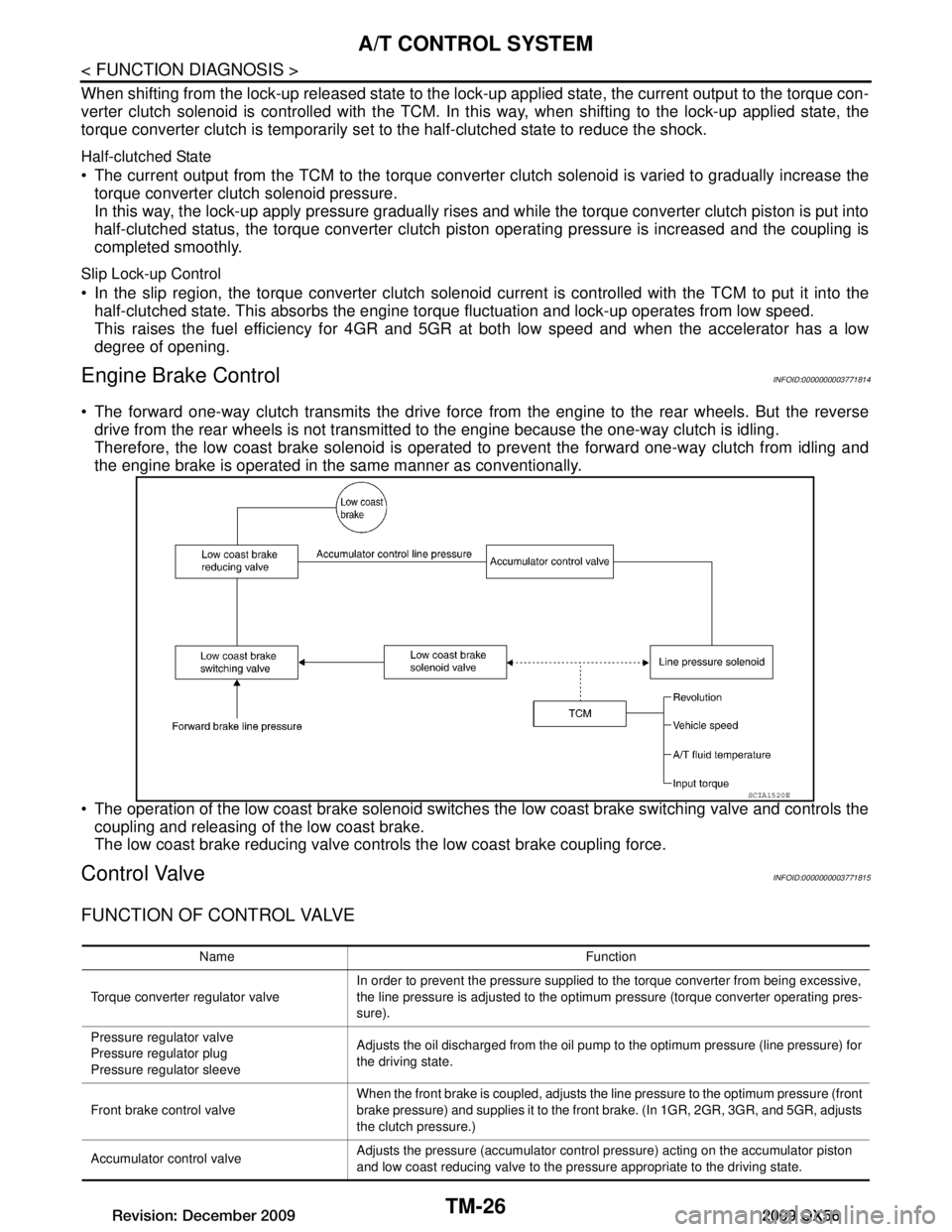
The forward one-way clutch transmits the drive force from the engine to the rear wheels. But the reverse
drive from the rear wheels is not transmitted to the engine because the one-way clutch is idling.
Therefore, the low coast brake solenoid is operated to prevent the forward one-way clutch from idling and
the engine brake is operated in the same manner as conventionally.
The operation of the low coast brake solenoid switches the low coast brake switching valve and controls the
coupling and releasing of the low coast brake.
The low coast brake reducing valve contro ls the low coast brake coupling force.
Control ValveINFOID:0000000003771815
FUNCTION OF CONTROL VALVE
SCIA1520E
Name Function
Torque converter regulator valve In order to prevent the pressure supplied to the torque converter from being excessive,
the line pressure is adjusted to the optimum pressure (torque converter operating pres-
sure).
Pressure regu lator valve
Pressure regulator plug
Pressure regu lator sleeve Adjusts the oil discharged from the oil pump to the optimum pressure (line pressure) for
the driving state.
Front brake control valve When the front brake is coupled, adjusts the line pressure to the optimum pressure (front
brake pressure) and supplies it to the front brake. (In 1GR, 2GR, 3GR, and 5GR, adjusts
the clutch pressure.)
Accumulator control valve Adjusts the pressure (accumulator control pressure) acting on the accumulator piston
and low coast reducing valve to the pressure appropriate to the driving state.
Revision: December 20092009 QX56
Page 3683 of 4171

DIAGNOSIS SYSTEM (TCM)TM-35
< FUNCTION DIAGNOSIS >
CEF
G H
I
J
K L
M A
B
TM
N
O P
RANGE SW 1 (ON-OFF display) X — X
RANGE SW 2 (ON-OFF display) X — X
RANGE SW 3 (ON-OFF display) X — X
RANGE SW 4 (ON-OFF display) X — X
SLCT LVR POSI — X X Selector lever position is recognized by the TCM.
For fail-safe operation, the specific value used
for control is displayed.
1 POSITION SW (ON-OFF display) X — X 1st position switch
OD CONT SW (ON-OFF display) X — X 4th position switch
POWERSHIFT SW (ON-OFF display) X — X
Not mounted but displayed.
HOLD SW (ON-OFF display) X — X
MANU MODE SW (ON-OFF display) X — X
NON M-MODE SW (ON-OFF display) X — X
UP SW LEVER (ON-OFF display) X — X
DOWN SW LEVER (ON-OFF display) X — X
SFT UP ST SW (ON-OFF display) — — X
SFT DWN ST SW (ON-OFF display) — — X
ASCD-OD CUT (ON-OFF display) — — X
ASCD-CRUISE (ON-OFF display) — — X
ABS SIGNAL (ON-OFF display) — — X
ACC OD CUT (ON-OFF display) — — X
ICC (Intelligent cruise control)
ACC SIGNAL (ON-OFF display) — — X
TCS GR/P KEEP (ON-OFF display) — — X
TCS SIGNAL 2 (ON-OFF display) — — X
TCS SIGNAL 1 (ON-OFF display) — — X
TCC SOLENOID (A) — X X
LINE PRES SOL (A) — X X
I/C SOLENOID (A) — X X
FR/B SOLENOID (A) — X X
D/C SOLENOID (A) — X X
HLR/C SOL (A) — X X
ON OFF SOL (ON-OFF display) — — X LC/B solenoid
TCC SOL MON (A) — — X
L/P SOL MON (A) — — X
I/C SOL MON (A) — — X
FR/B SOL MON (A) — — X
D/C SOL MON (A) — — X
HLR/C SOL MON (A) — — X
ONOFF SOL MON (ON-OFF display) — — X LC/B solenoid
P POSI IND (ON-OFF display) — — X
R POSI IND (ON-OFF display) — — X
N POSI IND (ON-OFF display) — — X Monitored item (Unit)
Monitor Item Selection
Remarks
ECU IN-
PUT SIG- NALS MAIN SIG-
NALS SELEC-
TION
FROM
MENU
Revision: December 20092009 QX56
Page 3943 of 4171
PRECAUTIONSVTL-3
< PRECAUTION >
C
DE
F
G H
J
K L
M A
B
VTL
N
O P
5. When the repair work is completed, return the ignition switch to the ″LOCK ″ position before connecting
the battery cables. (At this time, the steering lock mechanism will engage.)
6. Perform a self-diagnosis check of al l control units using CONSULT-III.
Precaution for Working with HFC-134a (R-134a)INFOID:0000000003775256
WARNING:
• CFC-12 (R-12) refrigerant and HFC-134a (R-134a) refr igerant are not compatible. If the refrigerants
are mixed compressor failure is likely to occur. Refer to HA-4, "
Contaminated Refrigerant". To deter-
mine the purity of HFC-134a (R-134a) in the vehicle and recovery tank, use recovery/recycling equip-
ment and refrigerant identifier.
• Use only specified oil for the HFC-134a (R-134a) A/C system and HFC-134a (R-134a) components. If
oil other than that specified is used, compressor fa ilure is likely to occur.
• The specified HFC-134a (R-134a) oil rapidly absorb s moisture from the atmosphere. The following
handling precautions must be observed:
- When removing refrigerant components from a vehicle, immediately cap (seal) the component to
minimize the entry of mois ture from the atmosphere.
- When installing refrigerant components to a vehicle, do not remove the caps (unseal) until just
before connecting the co mponents. Connect all refrigerant lo op components as quickly as possible
to minimize the entry of moisture into system.
- Only use the specified oil from a sealed container. Immediately r eseal containers of oil. Without
proper sealing, oil will become moisture saturat ed and should not be used.
- Avoid breathing A/C refrigerant and oil vapor or mist. Exposure may irritate eyes, nose and throat.
Remove HFC-134a (R-134a) from the A/C system usi ng certified service equipment meeting require-
ments of SAE J2210 [HFC-134a (R-134a) recycling eq uipment], or J2209 [HFC-134a (R-134a) recovery
equipment]. If accidental system discharge occurs , ventilate work area before resuming service.
Additional health and safety information may be ob tained from refrigerant and oil manufacturers.
- Do not allow A/C oil to come in contact with styrofoam parts. Damage may result.
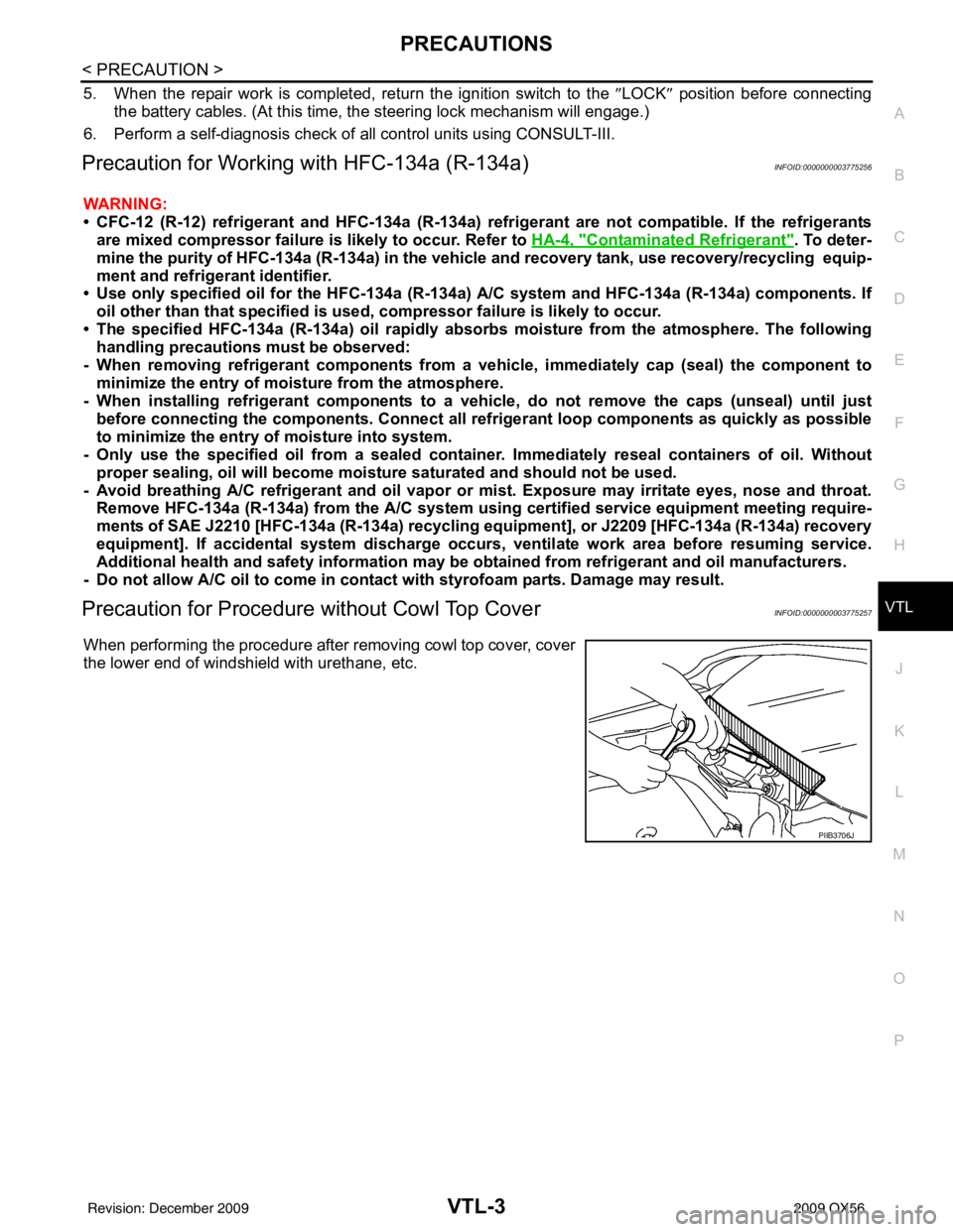
Precaution for Procedur e without Cowl Top CoverINFOID:0000000003775257
When performing the procedure after removing cowl top cover, cover
the lower end of windshield with urethane, etc.
PIIB3706J
Revision: December 20092009 QX56
Page 3989 of 4171

WCS-12
< FUNCTION DIAGNOSIS >
DIAGNOSIS SYSTEM (METER)
DIAGNOSIS SYSTEM (METER)
CONSULT-III Function (METER/M&A)INFOID:0000000004115456
CONSULT-III can display each diagnostic item using the diagnostic test modes shown following.
SELF-DIAG RESULTS
Display Item List
Refer to WCS-47, "DTC Index".
DATA MONITOR
Display Item List
X: Applicable
METER/M&A diagnosis mode Description
SELF-DIAG RESULTS Displays combination meter self-diagnosis results. DATA MONITOR Displays combination meter input/output data in real time.
CAN DIAG SUPPORT MNTR The result of transmit/receive diagnosis of CAN communication can be read.
Display item [Unit] MAIN
SIGNALS SELECTION
FROM MENU Description
SPEED METER [km/h] or [mph] X X Displays the value of vehicle speed signal.
SPEED OUTPUT [km/h] or [mph] X XDisplays the value of vehicle speed signal, which is transmitted to
each unit with
CAN communication.
TACHO METER [rpm] XX Displays the value of engine speed signal, which is input from ECM.
FUEL METER [lit.] XXDisplays the value, which processes a resistance signal from fuel
gauge.
W TEMP METER [ °C] or [° F] X XDisplays the value of engine coolant temperature signal, which is in-
put from ECM.
ABS W/L [ON/OFF] X Displays [ON/OFF] condition of ABS warning lamp.
VDC/TCS IND [ON/OFF] X Displays [ON/OFF] condition of VDC OFF indicator lamp.
SLIP IND [ON/OFF] X Displays [ON/OFF] condition of SLIP indicator lamp.
BRAKE W/L [ON/OFF] X Displays [ON/OFF] condition of brake warning lamp.*
DOOR W/L [ON/OFF] X Displays [ON/OFF] condition of door warning lamp.
TRUNK W/L [ON/OFF] X Displays [ON/OFF] condition of glass hatch warning lamp.
HI-BEAM IND [ON/OFF] X Displays [ON/OFF] condition of high beam indicator.
TURN IND [ON/OFF] X Displays [ON/OFF] conditio n of turn indicator.
OIL W/L [ON/OFF] X Displays [ON/OFF] condition of oil pressure warning lamp.
C-ENG W/L [ON/OFF] X Displays [ON/OFF] condition of malfunction indicator lamp.
CRUISE IND [ON/OFF] X Displays [ON/OFF] condition of CRUISE indicator.
SET IND [ON/OFF] X Displays [ON/OFF] condition of SET indicator.
AT CHECK W/L [ON/OFF] X Displays [ON/OFF] condition of AT CHECK warning lamp.
FUEL W/L [ON/OFF] XX Displays [ON/OFF] condition of low-fuel warning lamp.
AIR PRES W/L [ON/OFF] X Displays [ON/OFF] condition of tire pressure warning lamp.
KEY G W/L [ON/OFF] X Displays [ON/OFF] condition of key green warning lamp.
KEY R W/L [ON/OFF] X Displays [ON/OFF] condition of key red warning lamp.
KEY KNOB W/L [ON/OFF] X Displays [ON/OFF] condition of key knob warning lamp.
M RANGE SW [ON/OFF] XX Displays [ON/OFF] condition of manual mode range switch.
NM RANGE SW [ON/OFF] XXDisplays [ON/OFF] condition of except for manual mode range
switch.
AT SFT UP SW [ON/OFF] XX Displays [ON/OFF] condition of A/T shift-up switch.
Revision: December 20092009 QX56
Page 4024 of 4171
WCS
COMBINATION METERWCS-47
< ECU DIAGNOSIS >
C
DE
F
G H
I
J
K L
M B A
O P
DTC IndexINFOID:0000000004115463
Function Specifications
Speedometer
Zero indication.
Tachometer
Fuel gauge
Engine coolant temperature gauge
Engine oil pressure gauge
Voltage gauge
A/T oil temperature gauge
Illumination control
Meter illumination Change to nighttime mode when communication is lost.
Segment LCD Odometer
Freeze current indication.
A/T position Display turns off.
Buzzer Buzzer turns off.
Warning lamp/indicator lamp ABS warning lamp
Lamp turns on when communication is lost.
Brake warning lamp
VDC OFF indicator lamp
SLIP indicator lamp
A/T CHECK warning lamp
Lamp turns off when communication is lost.
Oil pressure/coolant temperature
warning lamp
Light indicator
Malfunction indicator lamp
Master warning lamp
Air bag warning lamp
High beam indicator
Turn signal indicator lamp
CRUISE indicator lamp
Driver and passenger seat belt warn-
ing lamp
Lamp turns off when disconnected.
Charge warning lamp
Security indicator lamp
4WD indicator lamp
ATP indicator lamp
CK SUSP warning lamp
Low tire pressu
re warning lamp Lamp will flash every second for 1 minute and then stay on con-
tinuously thereafter.
CONSULT-III display
MalfunctionReference
page
CAN COMM CIRC
[U1000] Malfunction is detected in CAN communication.
CAUTION:
Even when there is no ma
lfunction on CAN communication system, malfunction may be
misinterpreted when battery has low voltag e (when maintaining 7 - 8 V for about 2 sec-
onds) or 10A fuse [No. 19, located in the fuse block (J/B)] is disconnected. MWI-28
VEHICLE SPEED
CIRC
[B2205]Malfunction is detected when an erroneous speed signal is input.
CAUTION:
Even when there is no malfunction on speed signal system, malfunction may be misin-
terpreted when battery has low voltage (whe
n maintaining 7 - 8 V for about 2 seconds). MWI-29
Revision: December 20092009 QX56