2009 INFINITI QX56 oil level
[x] Cancel search: oil levelPage 1408 of 4171
![INFINITI QX56 2009 Factory Service Manual
TROUBLE DIAGNOSIS - SPECIFICATION VALUEEC-81
< COMPONENT DIAGNOSIS > [VK56DE]
C
D
E
F
G H
I
J
K L
M A
EC
NP
O
Disconnection, looseness, and cracks in air duct
Looseness of oil filler cap
Discon INFINITI QX56 2009 Factory Service Manual
TROUBLE DIAGNOSIS - SPECIFICATION VALUEEC-81
< COMPONENT DIAGNOSIS > [VK56DE]
C
D
E
F
G H
I
J
K L
M A
EC
NP
O
Disconnection, looseness, and cracks in air duct
Looseness of oil filler cap
Discon](/manual-img/42/57031/w960_57031-1407.png)
TROUBLE DIAGNOSIS - SPECIFICATION VALUEEC-81
< COMPONENT DIAGNOSIS > [VK56DE]
C
D
E
F
G H
I
J
K L
M A
EC
NP
O
Disconnection, looseness, and cracks in air duct
Looseness of oil filler cap
Disconnection of oil level gauge
Open stuck, breakage, hose disconnection, or cracks of PCV valve
Disconnection or cracks of EVAP purge hose, open stuck
of EVAP canister purge volume control solenoid
valve
Malfunctioning seal of rocker cover gasket
Disconnection, looseness, or cracks of hoses, such as vacuum hose, connecting to intake air system parts
Malfunctioning seal of intake air system, etc.
>> GO TO 30.
29.CHECK “A/F ALPHA-B1”, “A/F ALPHA-B2”, AND “B/FUEL SCHDL”
Select “A/F ALPHA-B1”, “A/F ALPHA-B2”, and “B/F UEL SCHDL” in “SPEC” of “DATA MONITOR” mode, and
make sure that the each indication is within the SP value.
OK or NG
OK >> INSPECTION END
NG >> Detect malfunctioning part according to EC-475, "Symptom Matrix Chart"
.
30.CHECK “B/FUEL SCHDL”
Select “B/FUEL SCHDL” in “SPEC” of “DATA MONITO R” mode, and then make sure that the indication is
within the SP value.
OK or NG
OK >> INSPECTION END
NG >> Detect malfunctioning part according to EC-475, "Symptom Matrix Chart"
.
Revision: December 20092009 QX56
Page 1625 of 4171
![INFINITI QX56 2009 Factory Service Manual
EC-298
< COMPONENT DIAGNOSIS >[VK56DE]
P1217 ENGINE OVER TEMPERATURE
P1217 ENGINE OVER TEMPERATURE
On Board Diagn
osis LogicINFOID:0000000003771589
NOTE:
If DTC P1217 is displayed with DTC U1000 or INFINITI QX56 2009 Factory Service Manual
EC-298
< COMPONENT DIAGNOSIS >[VK56DE]
P1217 ENGINE OVER TEMPERATURE
P1217 ENGINE OVER TEMPERATURE
On Board Diagn
osis LogicINFOID:0000000003771589
NOTE:
If DTC P1217 is displayed with DTC U1000 or](/manual-img/42/57031/w960_57031-1624.png)
EC-298
< COMPONENT DIAGNOSIS >[VK56DE]
P1217 ENGINE OVER TEMPERATURE
P1217 ENGINE OVER TEMPERATURE
On Board Diagn
osis LogicINFOID:0000000003771589
NOTE:
If DTC P1217 is displayed with DTC U1000 or U1001, first perform the trouble diagnosis for DTC
U1000, U1001. Refer to EC-86
.
If DTC P1217 is displayed with DTC P0607, first pe rform the trouble diagnosis for DTC P0607. Refer
to EC-284
.
If the cooling fan or another component in the coo ling system malfunctions, engine coolant temperature will
rise.
When the engine coolant temperature reaches an abnorma lly high temperature condition, a malfunction is
indicated.
This self-diagnosis has the one trip detection logic.
CAUTION:
When a malfunction is indicated, be su re to replace the coolant. Refer to CO-11, "Changing Engine
Coolant". Also, replace the engine oil. Refer to LU-9, "Changing Engine Oil".
1. Fill radiator with coolant up to specified level with a filling speed of 2 liters per minute. Be sure to
use coolant with the proper mixture ratio. Refer to CO-10
.
2. After refilling coolant, run engine to en sure that no water-flow noise is emitted.
Overall Function CheckINFOID:0000000003771590
Use this procedure to check the overall function of the cooling fan. During this check, a DTC might not be con-
firmed.
WARNING:
Never remove the radiator cap and/or reservoir tank cap when the engine is hot. Serious burns could
be caused by high pressure fluid escaping fr om the radiator and/or reservoir tank.
Wrap a thick cloth around cap. Carefully remove the cap by turning it a quarter turn to allow built-up
pressure to escape. Then turn the cap all the way off.
WITH CONSULT-III
1. Check the coolant level in the reservoir tank and radiator. Allow engine to cool before checking coolant level.
If the coolant level in the reservoir tank and/or radiator is below
the proper range, skip the following steps and go to EC-388,
"Diagnosis Procedure".
2. Confirm whether customer filled the coolant or not. If customer
filled the coolant, skip the following steps and go to EC-388,
"Diagnosis Procedure".
3. Turn ignition switch ON.
DTC No. Trouble diagnosis name DTC detecting condition Possible cause
P1217
1217 Engine over tempera-
ture (Overheat) Cooling fan does not operate properly (Over-
heat).
Cooling fan system does not operate proper-
ly (Overheat).
Engine coolant was not added to the system using the proper filling method.
Engine coolant is not within the specified range. Harness or connectors
(The cooling fan circuit is open or short-
ed.)
Cooling fan
Cooling fan (crankshaft diven)
IPDM E/R (Cooling fan relay)
Radiator hose
Radiator
Radiator cap
Reservoir tank
Reservoir tank cap
Water pump
Thermostat
For more informat ion, refer to EC-300,
"Main 13 Causes of Overheating".
SEF621W
Revision: December 20092009 QX56
Page 1805 of 4171
![INFINITI QX56 2009 Factory Service Manual
EC-478
< SYMPTOM DIAGNOSIS >[VK56DE]
ENGINE CONTROL SYSTEM SYMPTOMS
1 - 6: The numbers refer to the order of inspection.Exhaust Exhaust manifold/Tube/Muffler/
Gasket 55555 55 5 EM-30
,
EX-
5Three wa INFINITI QX56 2009 Factory Service Manual
EC-478
< SYMPTOM DIAGNOSIS >[VK56DE]
ENGINE CONTROL SYSTEM SYMPTOMS
1 - 6: The numbers refer to the order of inspection.Exhaust Exhaust manifold/Tube/Muffler/
Gasket 55555 55 5 EM-30
,
EX-
5Three wa](/manual-img/42/57031/w960_57031-1804.png)
EC-478
< SYMPTOM DIAGNOSIS >[VK56DE]
ENGINE CONTROL SYSTEM SYMPTOMS
1 - 6: The numbers refer to the order of inspection.Exhaust Exhaust manifold/Tube/Muffler/
Gasket 55555 55 5 EM-30
,
EX-
5Three way catalyst
Lubrica-
tion Oil pan/Oil strainer/Oil pump/Oil
filter/Oil gallery/Oil cooler
55555 55 5 EM-33
,
LU-
14 , LU-11 ,
LU-12
Oil level (Low)/Filthy oil LU-8, "In-spection"
Cooling Radiator/Hose/Radiator filler cap
55555 55 45 CO-15
Thermostat 5
CO-22
Water pumpCO-20
Water galleryCO-6
Cooling fan 5CO-18,
CO-
19
Coolant level (Low)/Contaminat-
ed coolant 5
CO-10
IVIS (INFINITI Vehicle Immobilizer System —
NATS) 11
SEC-6
SYMPTOM
Reference
page
HARD/NO START/RESTART (EXCP. HA)
ENGINE STALL
HESITATION/SURGING/FLAT SPOT
SPARK KNOCK/DETONATION
LACK OF POWER/POOR ACCELERATION
HIGH IDLE/LOW IDLE
ROUGH IDLE/HUNTING
IDLING VIBRATION
SLOW/NO RETURN TO IDLE
OVERHEATS/WATER TEMPERATURE HIGH
EXCESSIVE FUEL CONSUMPTION
EXCESSIVE OIL CONSUMPTION
BATTERY DEAD (UNDER CHARGE)
Warranty symptom code AA AB AC AD AE AF AG AH AJ AK AL AM HA
Revision: December 20092009 QX56
Page 1846 of 4171
COMPRESSION PRESSUREEM-23
< ON-VEHICLE MAINTENANCE >
C
DE
F
G H
I
J
K L
M A
EM
NP
O
COMPRESSION PRESSURE
Checking Compression PressureINFOID:0000000005885870
1. Warm up the engine thoroughly. Then stop the engine.
2. Release the fuel pressure. Refer to EC-487, "
Fuel Pressure Check".
CAUTION:
If CONSULT-III is not used to release fuel pressure leave the fuel pump fuse disconnected until
step 7.
3. Remove the spark plug from each cylinder. Refer to EM-16, "
Removal and Installation".
4. Connect the engine tachometer (not required in use of CONSULT-III).
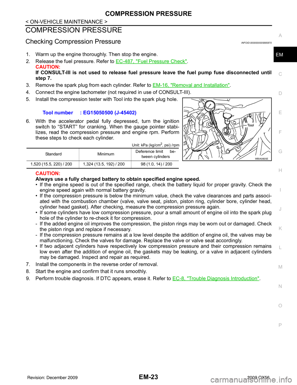
5. Install the compression tester with Tool into the spark plug hole.
6. With the accelerator pedal fully depressed, turn the ignition switch to “START” for cranking. When the gauge pointer stabi-
lizes, read the compression pressure and engine rpm. Perform
these steps to check each cylinder.
Unit: kPa (kg/cm2, psi) /rpm
CAUTION:
Always use a fully charged battery to obtain specified engine speed.
• If the engine speed is out of the specified range, check the battery liquid for proper gravity. Check the engine speed again with normal battery gravity.
• If the compression pressure is below the minimum value, check the valve clearances and parts associ-
ated with the combustion chamber (valve, valve seat , piston, piston ring, cylinder bore, cylinder head,
cylinder head gasket). After checking, measure the compression pressure again.
• If some cylinders have low compression pressure, pour a small amount of engine oil into the spark plug hole of the cylinder to re-check it for compression.
- If the added engine oil improves the compression, t he piston rings may be worn out or damaged. Check
the piston rings and replace if necessary.
- If the compression pressure remains at a low level despite the addition of engine oil, the valves may be malfunctioning. Check the valves for damage. Replace the valve or valve seat accordingly.
• If two adjacent cylinders have respectively low compression pressure and their compression remains low even after the addition of engine oil, the gaskets may be leaking, or a valve in adjacent cylinders
may be damaged. Inspect and repair as required.
7. Install the components in the reverse order of removal.
8. Start the engine and confirm that it runs smoothly.
9. Perform trouble diagnosis. If DTC appears, erase it. Refer to EC-8, "
Trouble Diagnosis Introduction".
Tool number : EG15050500 (J-45402)
Standard
MinimumDeference limit be-
tween cylinders
1,520 (15.5, 220) / 200 1,324 (13.5, 192) / 200 98 (1.0, 14) / 200WBIA0605E
Revision: December 20092009 QX56
Page 1851 of 4171
EM-28
< ON-VEHICLE REPAIR >
INTAKE MANIFOLD
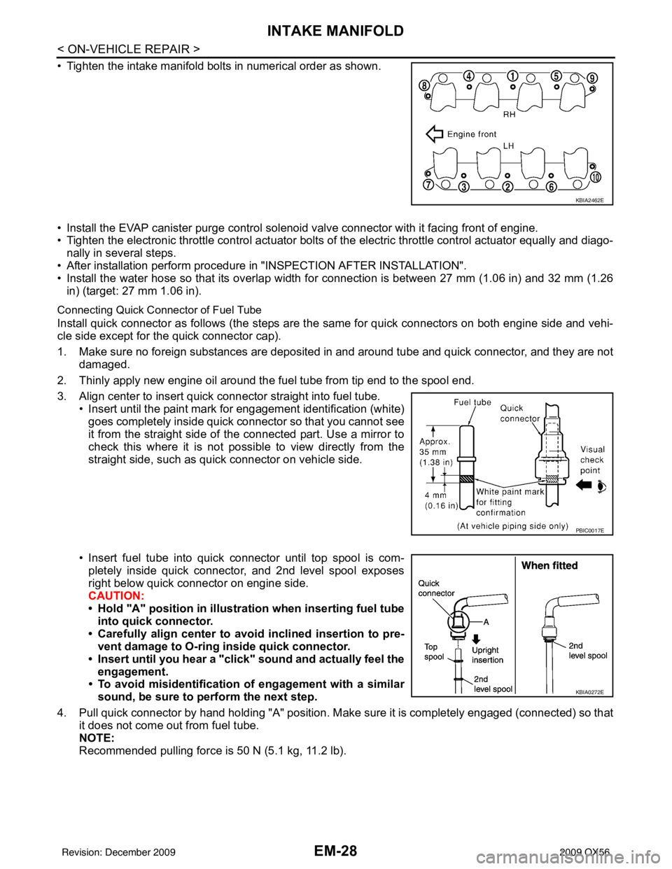
• Tighten the intake manifold bolts in numerical order as shown.
• Install the EVAP canister purge control solenoid valve connector with it facing front of engine.
• Tighten the electronic throttle control actuator bolts of the electric throttle control actuator equally and diago-
nally in several steps.
• After installation perform procedure in "INSPECTION AFTER INSTALLATION".
• Install the water hose so that its overlap width for connection is between 27 mm (1.06 in) and 32 mm (1.26 in) (target: 27 mm 1.06 in).
Connecting Quick Connector of Fuel Tube
Install quick connector as follows (the steps are t he same for quick connectors on both engine side and vehi-
cle side except for the quick connector cap).
1. Make sure no foreign substances are deposited in and around tube and quick connector, and they are not damaged.
2. Thinly apply new engine oil around the fuel tube from tip end to the spool end.
3. Align center to insert quick connector straight into fuel tube. • Insert until the paint mark for engagement identification (white)goes completely inside quick connector so that you cannot see
it from the straight side of the connected part. Use a mirror to
check this where it is not possible to view directly from the
straight side, such as quick connector on vehicle side.
• Insert fuel tube into quick connector until top spool is com- pletely inside quick connector, and 2nd level spool exposes
right below quick connector on engine side.
CAUTION:
• Hold "A" position in illustration when inserting fuel tubeinto quick connector.
• Carefully align center to avoid inclined insertion to pre-
vent damage to O-ring inside quick connector.
• Insert until you hear a "click" sound and actually feel the
engagement.
• To avoid misidentification of engagement with a similar
sound, be sure to pe rform the next step.
4. Pull quick connector by hand holding "A" position. Make sure it is completely engaged (connected) so that
it does not come out from fuel tube.
NOTE:
Recommended pulling force is 50 N (5.1 kg, 11.2 lb).
KBIA2462E
PBIC0017E
KBIA0272E
Revision: December 20092009 QX56
Page 1854 of 4171
EXHAUST MANIFOLD AND THREE WAY CATALYST
EM-31
< ON-VEHICLE REPAIR >
C
D E
F
G H
I
J
K L
M A
EM
NP
O
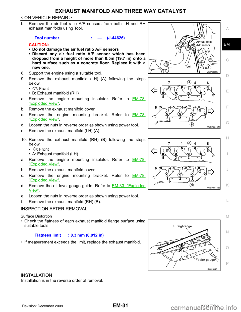
b. Remove the air fuel ratio A/F sensors from both LH and RH
exhaust manifolds using Tool.
CAUTION:
• Do not damage the air fuel ratio A/F sensors
• Discard any air fuel rati o A/F sensor which has been
dropped from a height of more than 0.5m (19.7 in) onto a
hard surface such as a concrete floor. Replace it with a
new one.
8. Support the engine using a suitable tool.
9. Remove the exhaust manifold (LH) (A) following the steps below.
• : Front
• B: Exhaust manifold (RH)
a. Remove the engine mounting insulator. Refer to EM-78,
"Exploded View".
b. Remove the exhaust manifold cover.
c. Remove the engine mounting bracket. Refer to EM-78,
"Exploded View".
d. Loosen the nuts in reverse order as shown using power tool.
e. Remove the exhaust manifold (LH) (A).
10. Remove the exhaust manifold (RH) (B) following the steps below.
• : Front
• A: Exhaust manifold (LH)
a. Remove the engine mounting insulator. Refer to EM-78,
"Exploded View".
b. Remove the exhaust manifold cover.
c. Remove the engine mounting bracket. Refer to EM-78,
"Exploded View".
d. Remove the oil level gauge guide. Refer to EM-33, "
Exploded
View".
e. Loosen the nuts in reverse order as shown using power tool.
f. Remove the exhaust manifold (RH) (B).
INSPECTION AFTER REMOVAL
Surface Distortion
• Check the flatness of each exhaust manifold flange surface using suitable tools.
• If measurement exceeds the limit, replace the exhaust manifold.
INSTALLATION
Installation is in the reverse order of removal. Tool number
: — (J-44626)
WBIA0630E
AWBIA0814ZZ
AWBIA0814ZZ
Flatness limit : 0.3 mm (0.012 in)
KBIA2504E
Revision: December 20092009 QX56
Page 1856 of 4171
OIL PAN AND OIL STRAINEREM-33
< ON-VEHICLE REPAIR >
C
DE
F
G H
I
J
K L
M A
EM
NP
O
OIL PAN AND OIL STRAINER
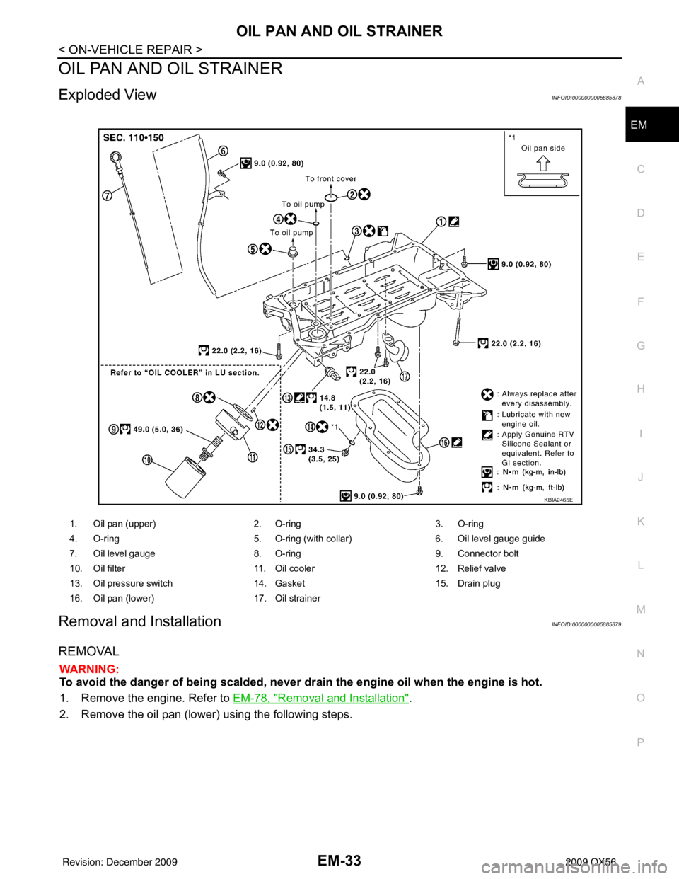
Exploded ViewINFOID:0000000005885878
Removal and InstallationINFOID:0000000005885879
REMOVAL
WARNING:
To avoid the danger of being scalded, never drain the engine oil when the engine is hot.
1. Remove the engine. Refer to
EM-78, "
Removal and Installation".
2. Remove the oil pan (lower) using the following steps.
1. Oil pan (upper) 2. O-ring3. O-ring
4. O-ring 5. O-ring (with collar)6. Oil level gauge guide
7. Oil level gauge 8. O-ring9. Connector bolt
10. Oil filter 11. Oil cooler12. Relief valve
13. Oil pressure switch 14. Gasket15. Drain plug
16. Oil pan (lower) 17. Oil strainer
KBIA2465E
Revision: December 20092009 QX56
Page 1859 of 4171
EM-36
< ON-VEHICLE REPAIR >
OIL PAN AND OIL STRAINER
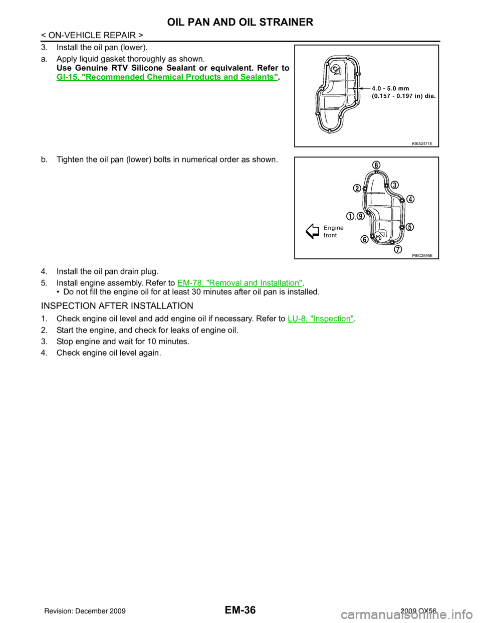
3. Install the oil pan (lower).
a. Apply liquid gasket thoroughly as shown.Use Genuine RTV Silicone Sealant or equivalent. Refer to
GI-15, "
Recommended Chemical Products and Sealants".
b. Tighten the oil pan (lower) bolts in numerical order as shown.
4. Install the oil pan drain plug.
5. Install engine assembly. Refer to EM-78, "
Removal and Installation".
• Do not fill the engine oil for at least 30 minutes after oil pan is installed.
INSPECTION AFTER INSTALLATION
1. Check engine oil level and add engine oil if necessary. Refer to LU-8, "Inspection".
2. Start the engine, and check for leaks of engine oil.
3. Stop engine and wait for 10 minutes.
4. Check engine oil level again.
KBIA2471E
PBIC2595E
Revision: December 20092009 QX56