2009 INFINITI QX56 oil level
[x] Cancel search: oil levelPage 2692 of 4171
ENGINE MAINTENANCEMA-19
< ON-VEHICLE MAINTENANCE >
C
DE
F
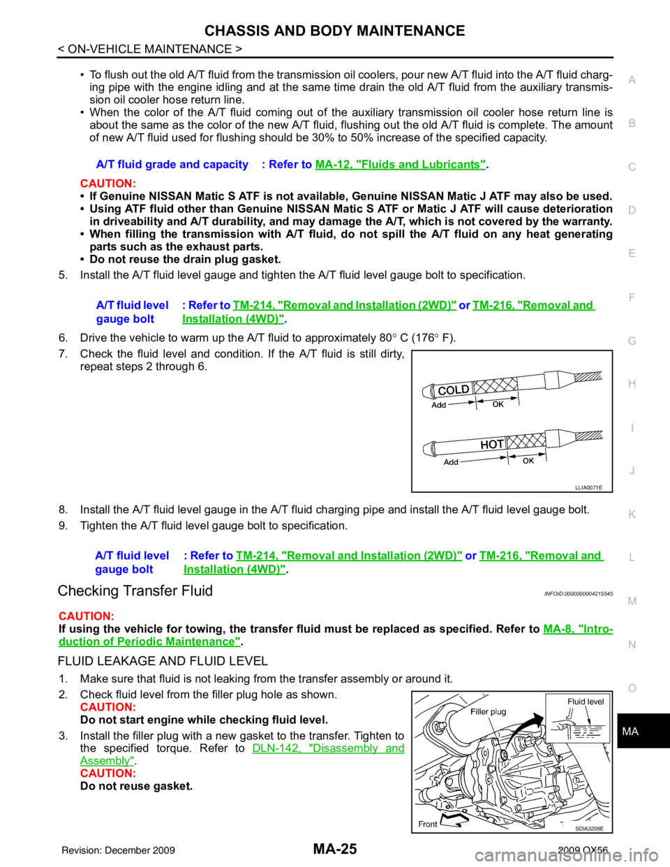
G H
I
J
K L
M B
MA
N
O A
• When removing, prepare a shop cloth to ab
sorb any engine oil leakage or spillage.
• Do not allow engine oil to adhere to the drive belts.
• Completely wipe off any engine oil that adheres to the engine and the vehicle.
INSTALLATION
1. Remove foreign materials adhering to the oil filter installation surface.
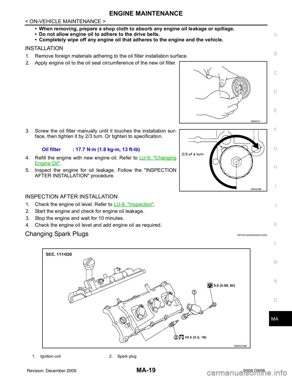
2. Apply engine oil to the oil seal circumference of the new oil filter.
3. Screw the oil filter manually until it touches the installation sur-
face, then tighten it by 2/3 turn. Or tighten to specification.
4. Refill the engine with new engine oil. Refer to LU-9, "
Changing
Engine Oil".
5. Inspect the engine for oil leakage. Follow the "INSPECTION AFTER INSTALLATION" procedure.
INSPECTION AFTER INSTALLATION
1. Check the engine oil level. Refer to LU-8, "Inspection".
2. Start the engine and check for engine oil leakage.
3. Stop the engine and wait for 10 minutes.
4. Check the engine oil level and add engine oil as required.
Changing Spark PlugsINFOID:0000000004215530
SMA010
Oil filter : 17.7 N·m (1.8 kg-m, 13 ft-lb)
SMA229B
1. Ignition coil 2. Spark plug
WBIA0796E
Revision: December 20092009 QX56
Page 2698 of 4171
CHASSIS AND BODY MAINTENANCEMA-25
< ON-VEHICLE MAINTENANCE >
C
DE
F
G H
I
J
K L
M B
MA
N
O A
• To flush out the old A/T fluid from the transmission o
il coolers, pour new A/T fluid into the A/T fluid charg-
ing pipe with the engine idling and at the same time drain the old A/T fluid from the auxiliary transmis-
sion oil cooler hose return line.
• When the color of the A/T fluid coming out of the aux iliary transmission oil cooler hose return line is
about the same as the color of the new A/T fluid, flushing out the old A/T fluid is complete. The amount
of new A/T fluid used for flushing should be 30% to 50% increase of the specified capacity.
CAUTION:
• If Genuine NISSAN Matic S ATF is not available, Genuine NISSAN Matic J ATF may also be used.
• Using ATF fluid other than Genuine NISSAN Matic S ATF or Matic J ATF will cause deterioration
in driveability and A/T durability, and may damage the A/T, which is not covered by the warranty.
• When filling the transmission with A/T fluid, do not spill the A/T fluid on any heat generating
parts such as the exhaust parts.
• Do not reuse the drain plug gasket.
5. Install the A/T fluid level gauge and tighten t he A/T fluid level gauge bolt to specification.
6. Drive the vehicle to warm up the A/T fluid to approximately 80 ° C (176 ° F).
7. Check the fluid level and condition. If the A/T fluid is still dirty, repeat steps 2 through 6.
8. Install the A/T fluid level gauge in the A/T fluid charging pipe and install the A/T fluid level gauge bolt.
9. Tighten the A/T fluid level gauge bolt to specification.
Checking Transfer FluidINFOID:0000000004215545
CAUTION:
If using the vehicle for towing, the transfer fluid must be replaced as specified. Refer to MA-8, "
Intro-
duction of Periodic Maintenance".
FLUID LEAKAGE AND FLUID LEVEL
1. Make sure that fluid is not leaking from the transfer assembly or around it.
2. Check fluid level from the filler plug hole as shown.
CAUTION:
Do not start engine while checking fluid level.
3. Install the filler plug with a new gasket to the transfer. Tighten to the specified torque. Refer to DLN-142, "
Disassembly and
Assembly".
CAUTION:
Do not reuse gasket. A/T fluid grade and capacity : Refer to MA-12, "
Fluids and Lubricants".
A/T fluid level
gauge bolt : Refer to
TM-214, "
Removal and Installation (2WD)" or TM-216, "Removal and
Installation (4WD)".
LLIA0071E
A/T fluid level
gauge bolt : Refer to TM-214, "Removal and Installation (2WD)" or TM-216, "Removal and
Installation (4WD)".
SDIA3209E
Revision: December 20092009 QX56
Page 2699 of 4171
MA-26
< ON-VEHICLE MAINTENANCE >
CHASSIS AND BODY MAINTENANCE
Changing Transfer Fluid
INFOID:0000000004215546
CAUTION:
If using the vehicle for towing, the transfer fluid must be replaced as specified. Refer to MA-8, "
Intro-
duction of Periodic Maintenance".
DRAINING
1. Stop engine.
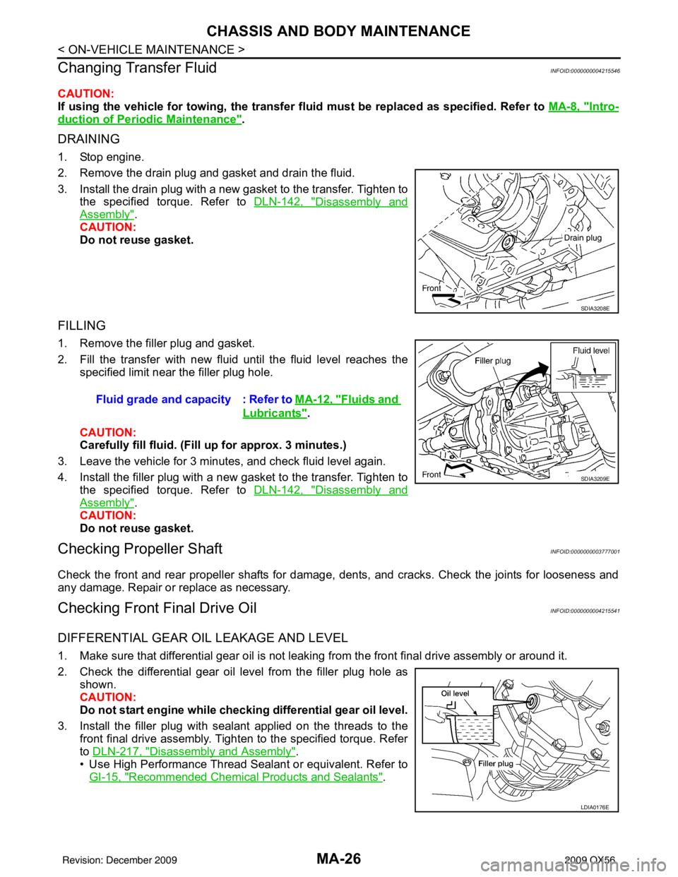
2. Remove the drain plug and gasket and drain the fluid.
3. Install the drain plug with a new gasket to the transfer. Tighten to
the specified torque. Refer to DLN-142, "
Disassembly and
Assembly".
CAUTION:
Do not reuse gasket.
FILLING
1. Remove the filler plug and gasket.
2. Fill the transfer with new fluid until the fluid level reaches the specified limit near the filler plug hole.
CAUTION:
Carefully fill fluid. (Fil l up for approx. 3 minutes.)
3. Leave the vehicle for 3 minutes, and check fluid level again.
4. Install the filler plug with a new gasket to the transfer. Tighten to the specified torque. Refer to DLN-142, "
Disassembly and
Assembly".
CAUTION:
Do not reuse gasket.
Checking Propeller ShaftINFOID:0000000003777001
Check the front and rear propeller shafts for damage, dents, and cracks. Check the joints for looseness and
any damage. Repair or replace as necessary.
Checking Front Final Drive OilINFOID:0000000004215541
DIFFERENTIAL GEAR OIL LEAKAGE AND LEVEL
1. Make sure that differential gear oil is not leaki ng from the front final drive assembly or around it.
2. Check the differential gear oil level from the filler plug hole as shown.
CAUTION:
Do not start engine while checki ng differential gear oil level.
3. Install the filler plug with sealant applied on the threads to the front final drive assembly. Tighten to the specified torque. Refer
to DLN-217, "
Disassembly and Assembly".
• Use High Performance Thread Sealant or equivalent. Refer to GI-15, "
Recommended Chemical Products and Sealants".
SDIA3208E
Fluid grade and capacity : Refer to MA-12, "Fluids and
Lubricants".
SDIA3209E
LDIA0176E
Revision: December 20092009 QX56
Page 2700 of 4171
CHASSIS AND BODY MAINTENANCEMA-27
< ON-VEHICLE MAINTENANCE >
C
DE
F
G H
I
J
K L
M B
MA
N
O A
Changing Front Final Drive OilINFOID:0000000004215542
DRAINING
1. Stop the engine.
2. Remove the drain plug from the front final drive assembly to drain the differential gear oil.
3. Install the drain plug with sealant applied on the thr
eads to the front final drive assembly. Tighten to the
specified torque. Refer to DLN-217, "
Disassembly and Assembly".
• Use High Performance Thread Sealant or equivalent. Refer to GI-15, "
Recommended Chemical Prod-
ucts and Sealants".
FILLING
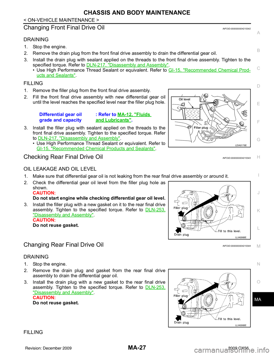
1. Remove the filler plug from the front final drive assembly.
2. Fill the front final drive assembly with new differential gear oil
until the level reaches the specified level near the filler plug hole.
3. Install the filler plug with sealant applied on the threads to the front final drive assembly. Tighten to the specified torque. Refer
to DLN-217, "
Disassembly and Assembly".
• Use High Performance Thread Sealant or equivalent. Refer to
GI-15, "
Recommended Chemical Products and Sealants".
Checking Rear Final Drive OilINFOID:0000000004215543
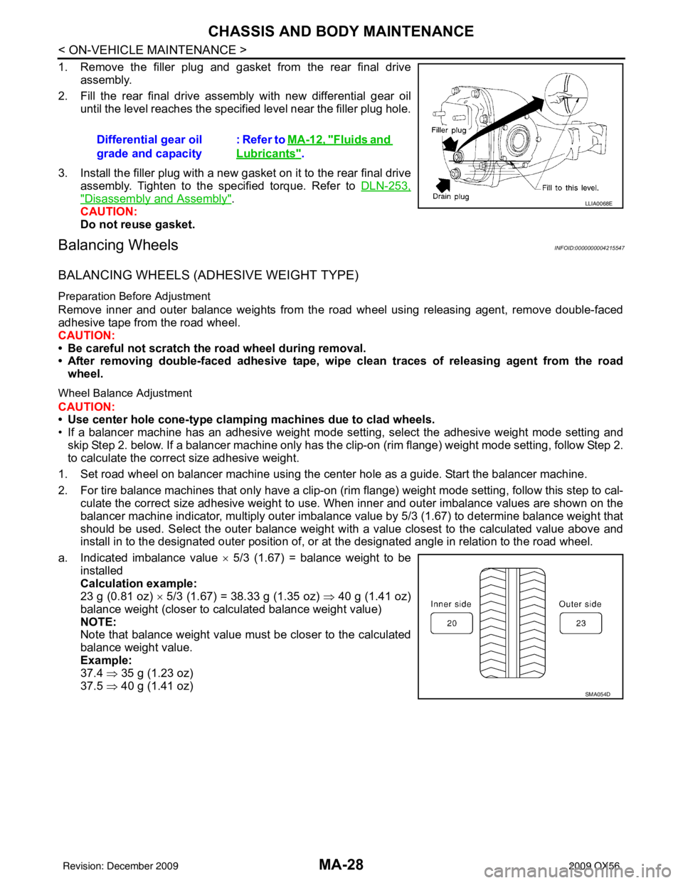
OIL LEAKAGE AND OIL LEVEL
1. Make sure that differential gear oil is not leaking from the rear final drive assembly or around it.
2. Check the differential gear oil level from the filler plug hole as shown.
CAUTION:
Do not start engine while checki ng differential gear oil level.
3. Install the filler plug with a new gasket on it to the rear final drive assembly. Tighten to the specified torque. Refer to DLN-253,
"Disassembly and Assembly".
CAUTION:
Do not reuse gasket.
Changing Rear Final Drive OilINFOID:0000000004215544
DRAINING
1. Stop the engine.
2. Remove the drain plug and gasket from the rear final drive assembly to drain the differential gear oil.
3. Install the drain plug with a new gasket to the rear final drive assembly. Tighten to the specified torque. Refer to DLN-253,
"Disassembly and Assembly".
CAUTION:
Do not reuse gasket.
FILLING
Differential gear oil
grade and capacity : Refer to
MA-12, "Fluids
and Lubricants".
LDIA0176E
LLIA0068E
LLIA0068E
Revision: December 20092009 QX56
Page 2701 of 4171
MA-28
< ON-VEHICLE MAINTENANCE >
CHASSIS AND BODY MAINTENANCE
1. Remove the filler plug and gasket from the rear final driveassembly.
2. Fill the rear final drive assembly with new differential gear oil until the level reaches the specified level near the filler plug hole.
3. Install the filler plug with a new gasket on it to the rear final drive assembly. Tighten to the specified torque. Refer to DLN-253,
"Disassembly and Assembly".
CAUTION:
Do not reuse gasket.
Balancing WheelsINFOID:0000000004215547
BALANCING WHEELS (ADHESIVE WEIGHT TYPE)
Preparation Before Adjustment
Remove inner and outer balance weights from the road wheel using releasing agent, remove double-faced
adhesive tape from the road wheel.
CAUTION:
• Be careful not scratch the road wheel during removal.
• After removing double-faced adhesive tape, wipe clean traces of releasing agent from the road
wheel.
Wheel Balance Adjustment
CAUTION:
• Use center hole cone-type clamping machines due to clad wheels.
• If a balancer machine has an adhesive weight mode se tting, select the adhesive weight mode setting and
skip Step 2. below. If a balancer machine only has the clip-on (rim flange) weight mode setting, follow Step 2.
to calculate the correct size adhesive weight.
1. Set road wheel on balancer machine using the center hole as a guide. Start the balancer machine.
2. For tire balance machines that only have a clip-on (rim flange) weight mode setting, follow this step to cal- culate the correct size adhesive weight to use. When inner and outer imbalance values are shown on the
balancer machine indicator, multiply outer imbalance value by 5/3 (1.67) to determine balance weight that
should be used. Select the outer balance weight with a value closest to the calculated value above and
install in to the designated outer position of, or at the designated angle in relation to the road wheel.
a. Indicated imbalance value × 5/3 (1.67) = balance weight to be
installed
Calculation example:
23 g (0.81 oz) × 5/3 (1.67) = 38.33 g (1.35 oz) ⇒ 40 g (1.41 oz)
balance weight (closer to calculated balance weight value)
NOTE:
Note that balance weight value must be closer to the calculated
balance weight value.
Example:
37.4 ⇒ 35 g (1.23 oz)
37.5 ⇒ 40 g (1.41 oz)
Differential gear oil
grade and capacity
: Refer to MA-12, "
Fluids and
Lubricants".
LLIA0068E
SMA054D
Revision: December 20092009 QX56
Page 2704 of 4171
CHASSIS AND BODY MAINTENANCEMA-31
< ON-VEHICLE MAINTENANCE >
C
DE
F
G H
I
J
K L
M B
MA
N
O A
PA D
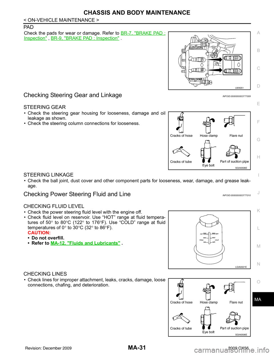
Check the pads for wear or damage. Refer to
BR-7, "BRAKE PAD :
Inspection" , BR-9, "BRAKE PAD : Inspection" .
Checking Steering Ge ar and LinkageINFOID:0000000003777009
STEERING GEAR
• Check the steering gear housing for looseness, damage and oil
leakage as shown.
• Check the steering column connections for looseness.
STEERING LINKAGE
• Check the ball joint, dust cover and other component parts for looseness, wear, damage, and grease leak-
age.
Checking Power Steering Fluid and LineINFOID:0000000003777010
CHECKING FLUID LEVEL
• Check the power steering fluid level with the engine off.
• Check fluid level on reservoir. Use “HOT” range at fluid tempera- tures of 50 ° to 80° C (122° to 176° F). Use “COLD” range at fluid
temperatures of 0 ° to 30° C (32° to 86° F).
CAUTION:
• Do not overfill.
• Refer to MA-12, "
Fluids and Lubricants" .
CHECKING LINES
• Check lines for improper attachment, leaks, cracks, damage, loose
connections, chafing, and deterioration.
LMA051
SGIA0506E
LGIA0021E
SGIA0506E
Revision: December 20092009 QX56
Page 2724 of 4171

MWI-2
INFORMATION DISPLAY .........................................19
INFORMATION DISPLAY : System Diagram .........20
INFORMATION DISPLAY : System Description ....20
INFORMATION DISPLAY : Component Parts Lo-
cation ................................................................... ...
21
INFORMATION DISPLAY : Component Descrip-
tion ....................................................................... ...
21
COMPASS .........................................................22
Description (Early Production) ............................. ...22
DIAGNOSIS SYSTEM (METER) .......................24
Diagnosis Description .......................................... ...24
CONSULT-III Function (METER/M&A) ................ ...25
COMPONENT DIAGNOSIS ........................28
DTC U1000 CAN COMMUNICATION ............ ...28
DTC Logic ............................................................ ...28
Diagnosis Procedure .............................................28
DTC B2205 VEHICLE SPEED CIRCUIT ...........29
Description ........................................................... ...29
DTC Logic ...............................................................29
Diagnosis Procedure .............................................29
POWER SUPPLY AND GROUND CIRCUIT .....30
COMBINATION METER ........................................ ...30
COMBINATION METER : Diagnosis Procedure ....30
BCM (BODY CONTROL MODULE) ...................... ...30
BCM (BODY CONTROL MODULE) : Diagnosis
Procedure ...............................................................
31
IPDM E/R (INTELLIGENT POWER DISTRIBU-
TION MODULE ENGINE ROOM) .......................... ...
31
IPDM E/R (INTELLIGENT POWER DISTRIBU-
TION MODULE ENGINE ROOM) : Diagnosis Pro-
cedure .....................................................................
31
FUEL LEVEL SENSOR SIGNAL CIRCUIT .......33
Description ........................................................... ...33
Component Function Check ...................................33
Diagnosis Procedure .............................................33
Component Inspection ............................................34
OIL PRESSURE SWITCH SIGNAL CIRCUIT ...35
Description ..............................................................35
Component Function Check ...................................35
Diagnosis Procedure ..............................................35
Component Inspection ............................................35
PARKING BRAKE SWITCH SIGNAL CIR-
CUIT ...................................................................
36
Description ........................................................... ...36
Component Function Check ...................................36
Diagnosis Procedure ..............................................36
Component Inspection ............................................36
WASHER LEVEL SWITCH SIGNAL CIRCUIT ...37
Description ........................................................... ...37
Diagnosis Procedure ............................................ ...37
Component Inspection ............................................37
COMPASS .........................................................38
Wiring Diagram (Early Production) ...................... ...38
CLOCK ..............................................................40
Wiring Diagram .................................................... ...40
ECU DIAGNOSIS .......................................42
COMBINATION METER ................................. ...42
Reference Value .................................................. ...42
Wiring Diagram .......................................................44
Fail Safe ..................................................................61
DTC Index ...............................................................62
BCM (BODY CONTROL MODULE) ..................64
Reference Value .................................................. ...64
Terminal Layout ......................................................66
Physical Values .......................................................66
Wiring Diagram .......................................................72
Fail Safe .................................................................76
DTC Inspection Priority Chart ...............................77
DTC Index ..............................................................77
IPDM E/R (INTELLIGENT POWER DISTRI-
BUTION MODULE ENGINE ROOM) .................
79
Reference Value .................................................. ...79
Terminal Layout ......................................................81
Physical Values .......................................................81
Wiring Diagram .......................................................86
Fail Safe .................................................................89
DTC Index ..............................................................91
SYMPTOM DIAGNOSIS ............................92
THE FUEL GAUGE POINTER DOES NOT
MOVE .............................................................. ...
92
Description ........................................................... ...92
Diagnosis Procedure ...............................................92
THE FUEL GAUGE POINTER DOES NOT
MOVE TO "F" WHEN REFUELING ..................
93
Description ........................................................... ...93
Diagnosis Procedure ...............................................93
THE OIL PRESSURE WARNING LAMP
DOES NOT TURN ON .................................... ...
94
Description ........................................................... ...94
Diagnosis Procedure ...............................................94
THE OIL PRESSURE WARNING LAMP
DOES NOT TURN OFF .................................. ...
95
Description ........................................................... ...95
Diagnosis Procedure ...............................................95
THE PARKING BRAKE RELEASE WARNING
CONTINUES DISPLAYING, OR DOES NOT
DISPLAY ............................................................
96
Description ........................................................... ...96
Revision: December 20092009 QX56
Page 2729 of 4171
MWI
METER SYSTEMMWI-7
< FUNCTION DIAGNOSIS >
C
DE
F
G H
I
J
K L
M B A
O P
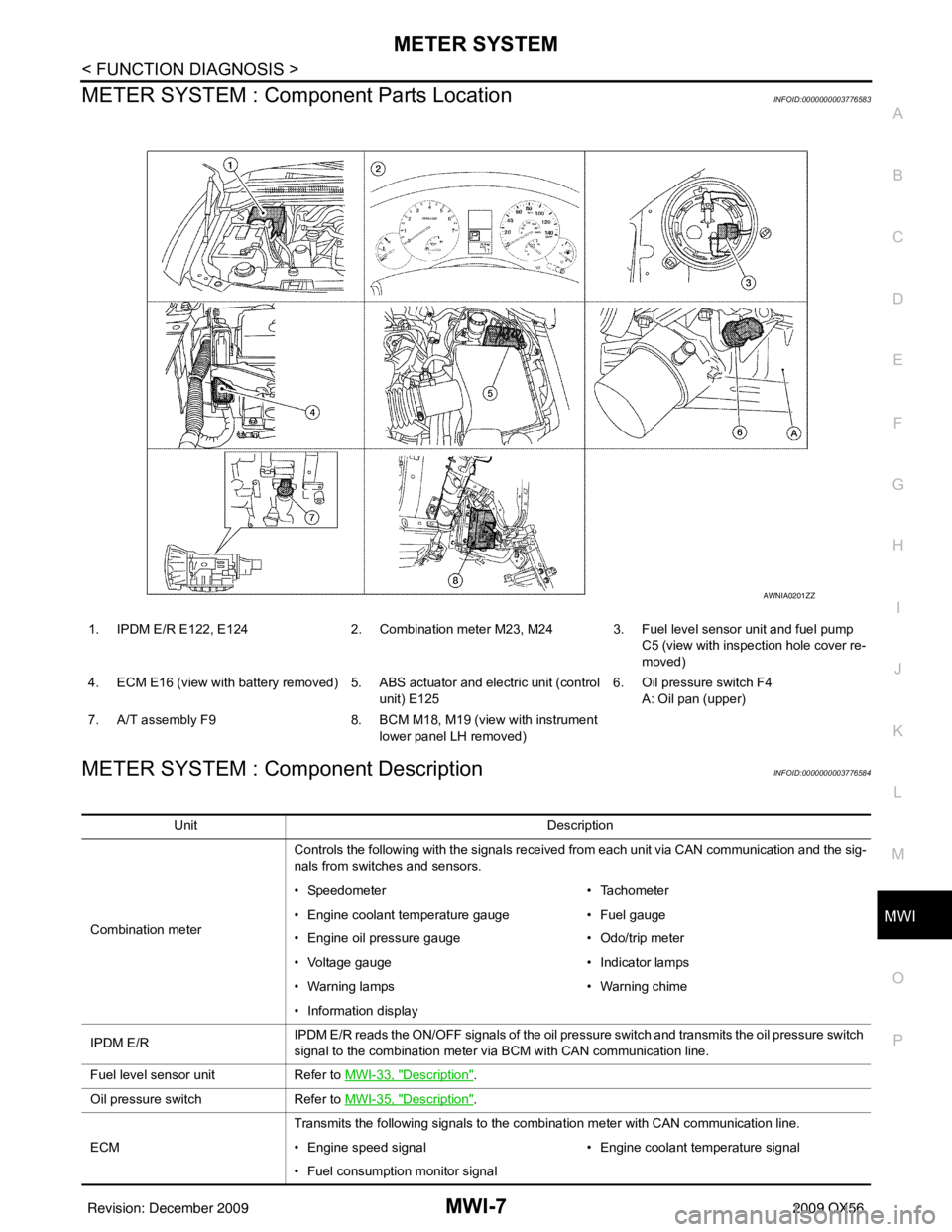
METER SYSTEM : Com ponent Parts LocationINFOID:0000000003776583
METER SYSTEM : Component DescriptionINFOID:0000000003776584
1. IPDM E/R E122, E124 2. Combination meter M23, M24 3. Fuel level sensor unit and fuel pump
C5 (view with inspection hole cover re-
moved)
4. ECM E16 (view with battery removed) 5. ABS actuator and electric unit (control unit) E1256. Oil pressure switch F4
A: Oil pan (upper)
7. A/T assembly F9 8. BCM M18, M19 (view with instrument
lower panel LH removed)
AWNIA0201ZZ
Unit Description
Combination meter Controls the following with the signals received from each unit via CAN communication and the sig-
nals from switches and sensors.
• Speedometer
• Tachometer
• Engine coolant temperature gauge • Fuel gauge
• Engine oil pressure gauge • Odo/trip meter
• Voltage gauge • Indicator lamps
• Warning lamps • Warning chime
• Information display
IPDM E/R IPDM E/R reads the ON/OFF signals of the oil pressure switch and transmits the oil pressure switch
signal to the combination meter via BCM with CAN communication line.
Fuel level sensor unit Refer to MWI-33, "
Description".
Oil pressure switch Refer to MWI-35, "
Description".
ECM Transmits the following signals to the combination meter with CAN communication line.
• Engine speed signal
• Engine coolant temperature signal
• Fuel consumption monitor signal
Revision: December 20092009 QX56