2009 INFINITI QX56 oil level
[x] Cancel search: oil levelPage 3592 of 4171

ST-1
STEERING
C
DE
F
H I
J
K L
M
SECTION ST
A
B
ST
N
O P
CONTENTS
STEERING SYSTEM
PRECAUTION ................ ...............................3
PRECAUTIONS .............................................. .....3
Precaution for Supplemental Restraint System
(SRS) "AIR BAG" and "SEAT BELT PRE-TEN-
SIONER" ............................................................. ......
3
Precaution Necessary for Steering Wheel Rota-
tion After Battery Disconnect .....................................
3
Precaution for Steering System ................................4
PREPARATION ............................................5
PREPARATION .............................................. .....5
Special Service Tool ........................................... ......5
Commercial Service Tool ..........................................6
FUNCTION DIAGNOSIS ...............................7
HEATED STEERING WHEEL ........................ .....7
System Diagram .................................................. ......7
System Description ...................................................7
Component Parts Location ........................................7
Component Description .............................................8
COMPONENT DIAGNOSIS ..........................9
HEATED STEERING WHEEL ........................ .....9
Wiring Diagram ................................................... ......9
SYMPTOM DIAGNOSIS ..............................12
NOISE, VIBRATION AND HARSHNESS
(NVH) TROUBLESHOOTING ........................ ....
12
NVH Troubleshooting Chart ................................ ....12
ON-VEHICLE MAINTENANCE ....................13
POWER STEERING FLUID ........................... ....13
Checking Fluid Level ........................................... ....13
Checking Fluid Leakage ..........................................13
Air Bleeding Hydraulic System ................................13
ON-VEHICLE REPAIR .................................15
STEERING WHEEL ..........................................15
On-Vehicle Inspection and Service ..................... ....15
POWER STEERING OIL PUMP .......................17
On-Vehicle Inspection and Service .........................17
REMOVAL AND INSTALLATION ...............18
STEERING WHEEL ..........................................18
Removal and Installation ..................................... ....18
TILT SYSTEM ...................................................19
Removal and Installation .........................................19
STEERING COLUMN ........................................20
Removal and Installation .........................................20
POWER STEERING GEAR AND LINKAGE ....23
Removal and Installation .........................................23
POWER STEERING OIL PUMP .......................26
Removal and Installation .........................................26
HYDRAULIC LINE ............................................27
Removal and Installation .........................................27
DISASSEMBLY AND ASSEMBLY ..............29
STEERING COLUMN ........................................29
Disassembly and Assembly ................................. ....29
POWER STEERING GEAR AND LINKAGE ....32
Disassembly and Assembly .....................................32
POWER STEERING OIL PUMP .......................35
Disassembly and Assembly .....................................35
SERVICE DATA AND SPECIFICATIONS
(SDS) ............... .............................................
36
SERVICE DATA AND SPECIFICATIONS
(SDS) .................................................................
36
Steering Wheel .................................................... ....36
Revision: December 20092009 QX56
Page 3604 of 4171

POWER STEERING FLUIDST-13
< ON-VEHICLE MAINTENANCE >
C
DE
F
H I
J
K L
M A
B
ST
N
O P
ON-VEHICLE MAINTENANCE
POWER STEERING FLUID
Checking Fluid LevelINFOID:0000000004187604
Check power steering fluid level with engine off, referring to the scale
on reservoir tank.
Use HOT range for fluid temperatures of 50 ° – 80 °C (122 ° – 176 °F).
Use COLD range for fluid temperatures of 0 ° – 30 °C (32 ° – 86 °F).
CAUTION:
Do not overfill.
Do not reuse any used power steering fluid.
Recommended fluid is Genuine NISSAN PSF or equivalent. Refer to MA-12, "Fluids and Lubricants"
.
Checking Fluid LeakageINFOID:0000000004187605
Check the hydraulic piping lines for improper attachment and for
leaks, cracks, damage, loose connections, chafing or deterioration.
1. Run engine until fluid temperature reaches 50 ° – 80 °C (122 ° –
176 °F) in reservoir tank. Keep engine speed idle.
2. Turn steering wheel right-to-left several times.
3. Hold steering wheel at each “lock” position for five seconds to check fluid leakage.
CAUTION:
Do not hold steering wheel in a locked position for more
than 10 seconds. (There is the possibility that oil pump may
be damaged.)
4. If fluid leakage at connections is noticed, then loos en flare nut and then retighten. Do not over tighten con-
nector as this can damage O-ring, washer and connector.
5. If fluid leakage from oil pump is noticed, check oil pump. Refer to ST-17
.
6. Check steering gear boots for accumulation of fluid indicating a leak from the steering gear.
Air Bleeding Hydraulic SystemINFOID:0000000005873142
NOTE:
When vehicle is stationary or while steering wheel is being turned slowly, some noise may be heard from oil pump or gear. This noise is normal and does not affect any system.
Incomplete air bleeding causes the fo llowing. When this happens, bleed air again.
- Air bubbles in reservoir tank.
- Clicking noise in oil pump.
- Excessive buzzing in oil pump.
1. Stop engine, and then turn steering wheel fully to right and left several times. CAUTION:
Do not allow steering fluid reservoir tank to go below the MIN level line. Check tank frequently and
add fluid as needed.
2. Run engine at idle speed. Turn steering wheel fully right and then fully left, hold for about three seconds.
Then check for fluid leakage.
3. Repeat step 2 several times at about three second intervals. CAUTION:
Do not hold steeri ng wheel in the locked position for more than 10 seconds. (There is the possibil-
ity that oil pump may be damaged.)
4. Check for air bubbles or cloudy fluid.
5. If air bubbles or cloudiness still exists, stop engine, perform steps 2 and 3 again until air bubbles or cloud-
iness does not exist.
LGIA0021E
SGIA0506E
Revision: December 20092009 QX56
Page 3769 of 4171
SYSTEM SYMPTOMTM-121
< SYMPTOM DIAGNOSIS >
CEF
G H
I
J
K L
M A
B
TM
N
O P
1.CHECK TRANSMISSION RANGE SWITCH CIRCUIT
Perform self-diagnosis. Refer to TM-32, "CONSULT-III Function (TRANSMISSION)"
.
Do the self-diagnostic results indicate transmission range switch?
YES >> Check the malfunctioning system. Refer to TM-44, "Diagnosis Procedure".
NO >> GO TO 2.
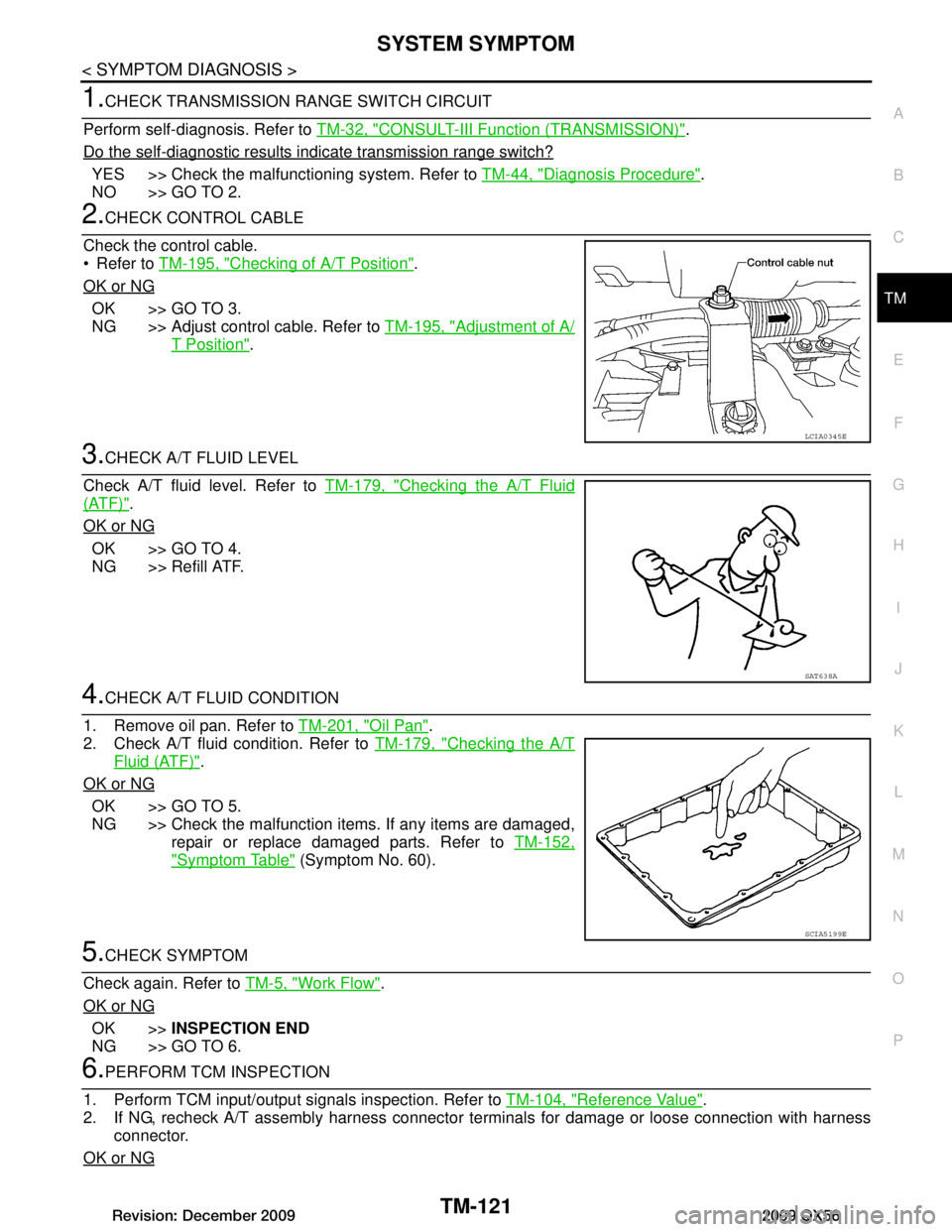
2.CHECK CONTROL CABLE
Check the control cable.
Refer to TM-195, "Checking of A/T Position"
.
OK or NG
OK >> GO TO 3.
NG >> Adjust control cable. Refer to TM-195, "Adjustment of A/
T Position".
3.CHECK A/T FLUID LEVEL
Check A/T fluid level. Refer to TM-179, "Checking the A/T Fluid
(ATF)".
OK or NG
OK >> GO TO 4.
NG >> Refill ATF.
4.CHECK A/T FLUID CONDITION
1. Remove oil pan. Refer to TM-201, "Oil Pan"
.
2. Check A/T fluid condition. Refer to TM-179, "Checking the A/T
Fluid (ATF)".
OK or NG
OK >> GO TO 5.
NG >> Check the malfunction items. If any items are damaged, repair or replace damaged parts. Refer to TM-152,
"Symptom Table" (Symptom No. 60).
5.CHECK SYMPTOM
Check again. Refer to TM-5, "Work Flow"
.
OK or NG
OK >> INSPECTION END
NG >> GO TO 6.
6.PERFORM TCM INSPECTION
1. Perform TCM input/output signals inspection. Refer to TM-104, "Reference Value"
.
2. If NG, recheck A/T assembly harness connector terminals for damage or loose connection with harness
connector.
OK or NG
LCIA0345E
SAT638A
SCIA5199E
Revision: December 20092009 QX56
Page 3775 of 4171
SYSTEM SYMPTOMTM-127
< SYMPTOM DIAGNOSIS >
CEF
G H
I
J
K L
M A
B
TM
N
O P
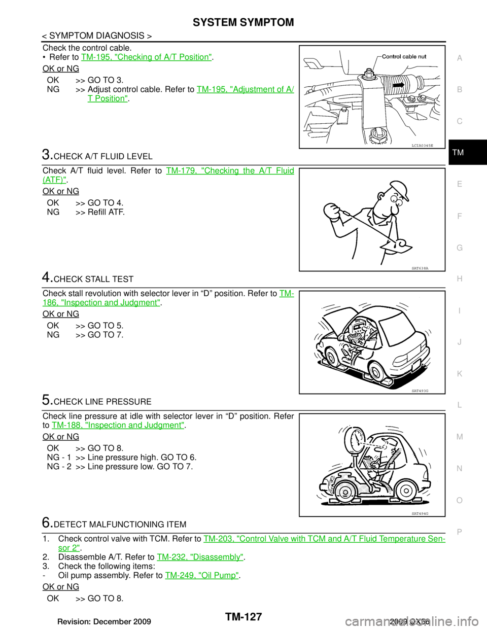
Check the control cable.
Refer to TM-195, "Checking of A/T Position"
.
OK or NG
OK >> GO TO 3.
NG >> Adjust control cable. Refer to TM-195, "Adjustment of A/
T Position".
3.CHECK A/T FLUID LEVEL
Check A/T fluid level. Refer to TM-179, "Checking the A/T Fluid
(ATF)".
OK or NG
OK >> GO TO 4.
NG >> Refill ATF.
4.CHECK STALL TEST
Check stall revolution with selector lever in “D” position. Refer to TM-
186, "Inspection and Judgment".
OK or NG
OK >> GO TO 5.
NG >> GO TO 7.
5.CHECK LINE PRESSURE
Check line pressure at idle with selector lever in “D” position. Refer
to TM-188, "Inspection and Judgment"
.
OK or NG
OK >> GO TO 8.
NG - 1 >> Line pressure high. GO TO 6.
NG - 2 >> Line pressure low. GO TO 7.
6.DETECT MALFUNCTIONING ITEM
1. Check control valve with TCM. Refer to TM-203, "Control Valve with TCM and A/T Fluid Temperature Sen-
sor 2".
2. Disassemble A/T. Refer to TM-232, "Disassembly"
.
3. Check the following items:
- Oil pump assembly. Refer to TM-249, "Oil Pump"
.
OK or NG
OK >> GO TO 8.
LCIA0345E
SAT638A
SAT493G
SAT494G
Revision: December 20092009 QX56
Page 3777 of 4171
SYSTEM SYMPTOMTM-129
< SYMPTOM DIAGNOSIS >
CEF
G H
I
J
K L
M A
B
TM
N
O P
Vehicle Cannot Be Started from D1INFOID:0000000003771998
SYMPTOM:
Vehicle cannot be started from D1 on cruise test - Part 1.
DIAGNOSTIC PROCEDURE
1.CONFIRM THE SYMPTOM
Check if vehicle creeps in “R” position.
OK or NG
OK >> GO TO 2.
NG >> Refer to TM-124, "Vehicle Does Not Creep Backward in "R" Position"
.
2.CHECK SELF-DIAGNOSTIC RESULTS
Perform self-diagnosis. Refer to TM-32, "CONSULT-III Function (TRANSMISSION)"
.
Is any malfunction detected by self-diagnostic results?
YES >> Check the malfunctioning system.
NO >> GO TO 3.
3.CHECK ACCELERATOR PEDA L POSITION(APP) SENSOR
Check accelerator pedal position (APP) sensor. Refer to TM-70, "Diagnosis Procedure"
.
OK or NG
OK >> GO TO 4.
NG >> Repair or replace accelerator pedal position (APP) sensor.
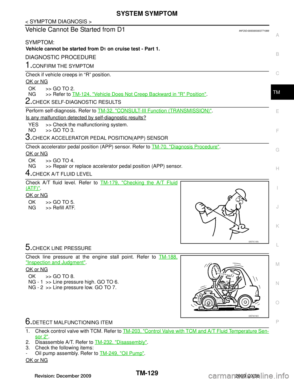
4.CHECK A/T FLUID LEVEL
Check A/T fluid level. Refer to TM-179, "Checking the A/T Fluid
(ATF)".
OK or NG
OK >> GO TO 5.
NG >> Refill ATF.
5.CHECK LINE PRESSURE
Check line pressure at the engine stall point. Refer to TM-188,
"Inspection and Judgment".
OK or NG
OK >> GO TO 8.
NG - 1 >> Line pressure high. GO TO 6.
NG - 2 >> Line pressure low. GO TO 7.
6.DETECT MALFUNCTIONING ITEM
1. Check control valve with TCM. Refer to TM-203, "Control Valve with TCM and A/T Fluid Temperature Sen-
sor 2".
2. Disassemble A/T. Refer to TM-232, "Disassembly"
.
3. Check the following items:
- Oil pump assembly. Refer to TM-249, "Oil Pump"
.
OK or NG
SAT638A
SAT494G
Revision: December 20092009 QX56
Page 3779 of 4171

SYSTEM SYMPTOMTM-131
< SYMPTOM DIAGNOSIS >
CEF
G H
I
J
K L
M A
B
TM
N
O P
A/T Does Not Shift: D1 →D2INFOID:0000000003771999
SYMPTOM:
The vehicle does not shift-up from the D1 to D2 gear at the specified speed.
DIAGNOSTIC PROCEDURE
1.CONFIRM THE SYMPTOM
Check if vehicle creeps forward in “D” position and vehicle can be started from D
1.
OK or NG
OK >> GO TO 2.
NG >> Refer to TM-126, "Vehicle Does Not Creep Forward in "D" Position"
, TM-129, "Vehicle Cannot Be
Started from D1".
2.CHECK SELF-DIAGNOSTIC RESULTS
Perform self-diagnosis. Refer to TM-32, "CONSULT-III Function (TRANSMISSION)"
.
Do the self-diagnostic results indicate, direct clutch solenoid valve, accelerator pedal position sensor, output
speed sensor and vehicle speed signal?
YES >> Check the malfunctioning system. Refer to TM-84, "Diagnosis Procedure", EC-374, "Diagnosis
Procedure", TM-50, "Diagnosis Procedure", TM-74, "Diagnosis Procedure".
NO >> GO TO 3.
3.CHECK A/T FLUID LEVEL
Check A/T fluid level. Refer to TM-179, "Checking the A/T Fluid
(ATF)".
OK or NG
OK >> GO TO 4.
NG >> Refill ATF.
4.CHECK LINE PRESSURE
Check line pressure at the engine stall point. Refer to TM-188,
"Inspection and Judgment".
OK or NG
OK >> GO TO 7.
NG - 1 >> Line pressure high. GO TO 5.
NG - 2 >> Line pressure low. GO TO 6.
5.DETECT MALFUNCTIONING ITEM
1. Check control valve with TCM. Refer to TM-203, "Control Valve with TCM and A/T Fluid Temperature Sen-
sor 2".
2. Disassemble A/T. Refer to TM-232, "Disassembly"
.
3. Check the following items:
- Oil pump assembly. Refer to TM-249, "Oil Pump"
.
OK or NG
OK >> GO TO 7.
NG >> Repair or replace damaged parts.
6.DETECT MALFUNCTIONING ITEM
SAT638A
SAT494G
Revision: December 20092009 QX56
Page 3781 of 4171
SYSTEM SYMPTOMTM-133
< SYMPTOM DIAGNOSIS >
CEF
G H
I
J
K L
M A
B
TM
N
O P
DIAGNOSTIC PROCEDURE
1.CONFIRM THE SYMPTOM
Check if vehicle creeps forward in “D” position and vehicle can be started from D
1.
OK or NG
OK >> GO TO 2.
NG >> Refer to TM-126, "Vehicle Does Not Creep Forward in "D" Position"
, TM-129, "Vehicle Cannot Be
Started from D1".
2.CHECK SELF-DIAGNOSTIC RESULTS
Perform self-diagnosis. Refer to TM-32, "CONSULT-III Function (TRANSMISSION)"
.
Do the self-diagnostic results indicate high and low reverse clutch solenoid valve, accelerator pedal position
sensor, output speed sensor and vehicle speed signal?
YES >> Check the malfuncti oning system. Refer to TM-86, "Diagnosis Procedure", EC-374, "Diagnosis
Procedure", TM-50, "Diagnosis Procedure", TM-74, "Diagnosis Procedure".
NO >> GO TO 3.
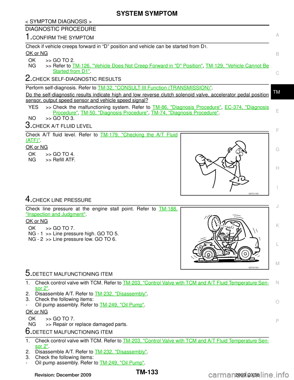
3.CHECK A/T FLUID LEVEL
Check A/T fluid level. Refer to TM-179, "Checking the A/T Fluid
(ATF)".
OK or NG
OK >> GO TO 4.
NG >> Refill ATF.
4.CHECK LINE PRESSURE
Check line pressure at the engine stall point. Refer to TM-188,
"Inspection and Judgment".
OK or NG
OK >> GO TO 7.
NG - 1 >> Line pressure high. GO TO 5.
NG - 2 >> Line pressure low. GO TO 6.
5.DETECT MALFUNCTIONING ITEM
1. Check control valve with TCM. Refer to TM-203, "Control Valve with TCM and A/T Fluid Temperature Sen-
sor 2".
2. Disassemble A/T. Refer to TM-232, "Disassembly"
.
3. Check the following items:
- Oil pump assembly. Refer to TM-249, "Oil Pump"
.
OK or NG
OK >> GO TO 7.
NG >> Repair or replace damaged parts.
6.DETECT MALFUNCTIONING ITEM
1. Check control valve with TCM. Refer to TM-203, "Control Valve with TCM and A/T Fluid Temperature Sen-
sor 2".
2. Disassemble A/T. Refer to TM-232, "Disassembly"
.
3. Check the following items:
- Oil pump assembly. Refer to TM-249, "Oil Pump"
.
SAT638A
SAT494G
Revision: December 20092009 QX56
Page 3783 of 4171
SYSTEM SYMPTOMTM-135
< SYMPTOM DIAGNOSIS >
CEF
G H
I
J
K L
M A
B
TM
N
O P
Check if vehicle creeps forward in “D” position and vehicle can be started from D1.
OK or NG
OK >> GO TO 2.
NG >> Refer to TM-126, "Vehicle Does Not Creep Forward in "D" Position"
, TM-129, "Vehicle Cannot Be
Started from D1".
2.CHECK SELF-DIAGNOSTIC RESULTS
Perform self-diagnosis. Refer to TM-32, "CONSULT-III Function (TRANSMISSION)"
.
Do the self-diagnostic results indicate front brake solenoid valve, input clutch solenoid valve, accelerator pedal
position sensor, output speed sensor and vehicle speed signal?
YES >> Check the malfunctioning system. Refer to TM-82, "Diagnosis Procedure", TM-80, "Diagnosis
Procedure", EC-374, "Diagnosis Procedure", TM-50, "Diagnosis Procedure", TM-74, "Diagnosis
Procedure".
NO >> GO TO 3.
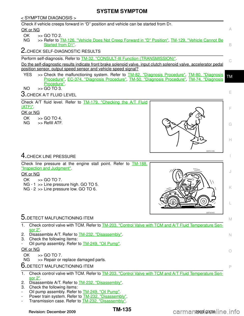
3.CHECK A/T FLUID LEVEL
Check A/T fluid level. Refer to TM-179, "Checking the A/T Fluid
(ATF)".
OK or NG
OK >> GO TO 4.
NG >> Refill ATF.
4.CHECK LINE PRESSURE
Check line pressure at the engine stall point. Refer to TM-188,
"Inspection and Judgment".
OK or NG
OK >> GO TO 7.
NG - 1 >> Line pressure high. GO TO 5.
NG - 2 >> Line pressure low. GO TO 6.
5.DETECT MALFUNCTIONING ITEM
1. Check control valve with TCM. Refer to TM-203, "Control Valve with TCM and A/T Fluid Temperature Sen-
sor 2".
2. Disassemble A/T. Refer to TM-232, "Disassembly"
.
3. Check the following items:
- Oil pump assembly. Refer to TM-249, "Oil Pump"
.
OK or NG
OK >> GO TO 7.
NG >> Repair or replace damaged parts.
6.DETECT MALFUNCTIONING ITEM
1. Check control valve with TCM. Refer to TM-203, "Control Valve with TCM and A/T Fluid Temperature Sen-
sor 2".
2. Disassemble A/T. Refer to TM-232, "Disassembly"
.
3. Check the following items:
- Oil pump assembly. Refer to TM-249, "Oil Pump"
.
- Power train system. Refer to TM-232, "Disassembly"
.
- Transmission case. Refer to TM-232, "Disassembly"
.
SAT638A
SAT494G
Revision: December 20092009 QX56