2009 INFINITI QX56 fuses
[x] Cancel search: fusesPage 1986 of 4171

EXL-38
< COMPONENT DIAGNOSIS >
FRONT FOG LAMP CIRCUIT
FRONT FOG LAMP CIRCUIT
DescriptionINFOID:0000000003776184
The IPDM E/R (intelligent power distribution module engine room) controls the front fog lamp relay based on
inputs from the BCM via the CAN communication lines. When the front fog lamp relay is energized, power
flows from the front fog lamp relay in the IPDM E/R to the front fog lamps.
Component Function CheckINFOID:0000000003776185
1.CHECK FRONT FOG LAMP OPERATION
WITHOUT CONSULT-III
1. Activate IPDM E/R auto active test. Refer to PCS-12, "
Diagnosis Description".
2. Check that the front fog lamp is turned ON.
CONSULT-III
1. Select "EXTERNAL LAMP" of IPDM E/R active test item.
2. With operating the test items, Check that the front fog lamp is turned ON.
Is the front fog lamp turned ON?
YES >> Front fog lamp circuit is normal.
NO >> Refer to EXL-38, "
Diagnosis Procedure".
Diagnosis ProcedureINFOID:0000000003776186
1.CHECK FRONT FOG LAMP FUSE
1. Turn the ignition switch OFF.
2. Check that the following fuses are not open.
Is the fuse open?
YES >> Repair the harness and replace the fuse.
NO >> GO TO 2.
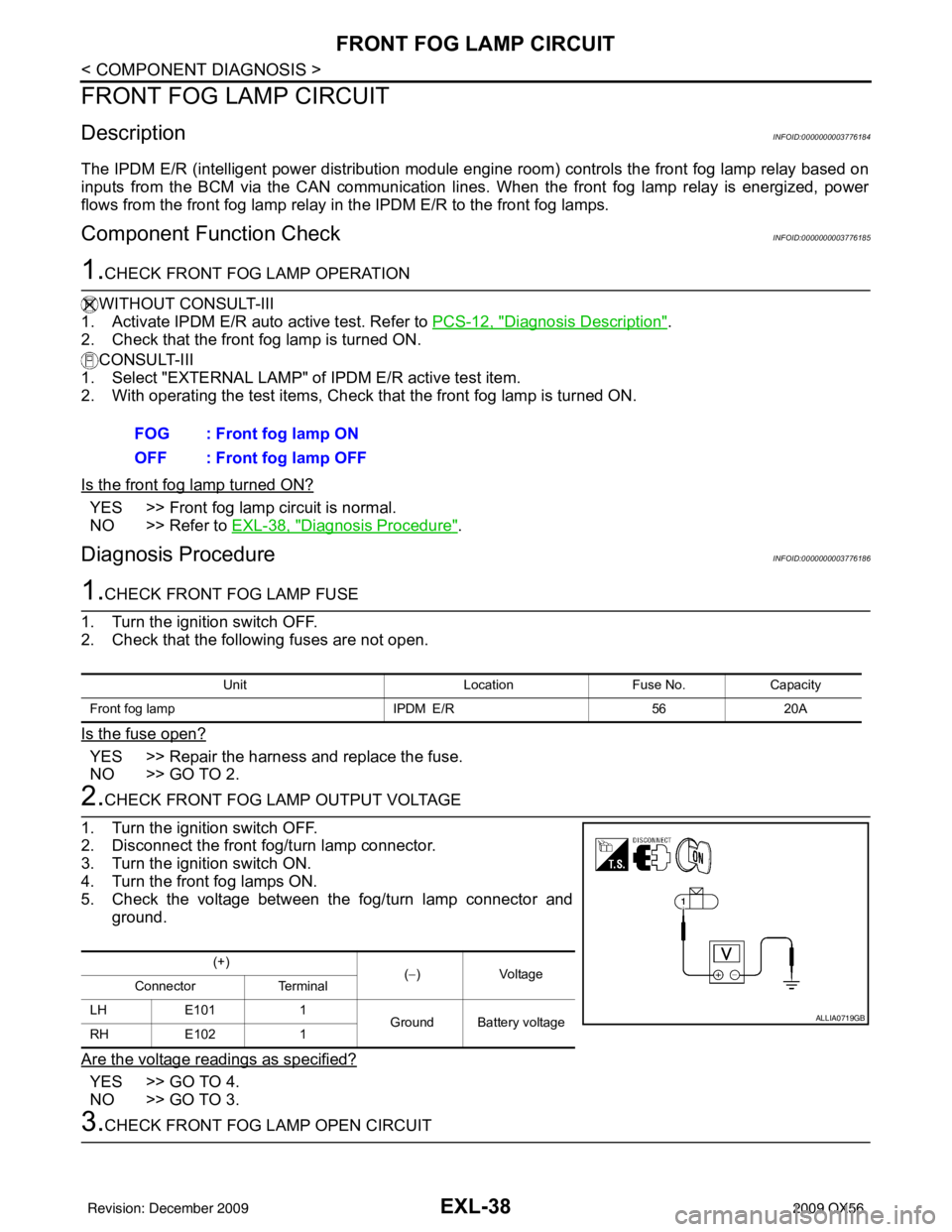
2.CHECK FRONT FOG LAMP OUTPUT VOLTAGE
1. Turn the ignition switch OFF.
2. Disconnect the front fog/turn lamp connector.
3. Turn the ignition switch ON.
4. Turn the front fog lamps ON.
5. Check the voltage between the fog/turn lamp connector and ground.
Are the voltage readings as specified?
YES >> GO TO 4.
NO >> GO TO 3.
3.CHECK FRONT FOG LAMP OPEN CIRCUIT FOG : Front fog lamp ON
OFF : Front fog lamp OFF
Unit
LocationFuse No.Capacity
Front fog lamp IPDM E/R5620A
(+)
(−)V olt a g e
Connector Terminal
LH E101 1
Ground Battery voltage
RH E102 1
ALLIA0719GB
Revision: December 20092009 QX56
Page 1988 of 4171

EXL-40
< COMPONENT DIAGNOSIS >
PARKING LAMP CIRCUIT
PARKING LAMP CIRCUIT
DescriptionINFOID:0000000003776187
The IPDM E/R (intelligent power distribution module engine room) controls the tail lamp relay based on inputs
from the BCM via the CAN communication lines. When the tail lamp relay is energized, power flows through
fuse 37, located in the IPDM E/R. Power then flows to the front and rear combination lamps.
Component Function CheckINFOID:0000000003776188
1.CHECK PARKING LAMP OPERATION
WITHOUT CONSULT-III
1. Activate IPDM E/R auto active test. Refer to PCS-12, "
Diagnosis Description".
2. Check that the parking lamp is turned ON.
CONSULT-III
1. Select "EXTERNAL LAMP" of IPDM E/R active test item.
2. With operating the test items, check that the parking lamp is turned ON.
Is the parking lamp turned ON?
YES >> Parking lamp circuit is normal.
NO >> Refer to EXL-40, "
Diagnosis Procedure - Without Daytime Light System", EXL-42, "Diagnosis
Procedure - With Daytime Light System".
Diagnosis Procedure - Wit hout Daytime Light SystemINFOID:0000000003776189
1.CHECK PARKING LAMP FUSES
1. Turn the ignition switch OFF.
2. Check that the following fuses are not open.
Is the fuse open?
YES >> Repair the harness and replace the fuse.
NO >> GO TO 2.
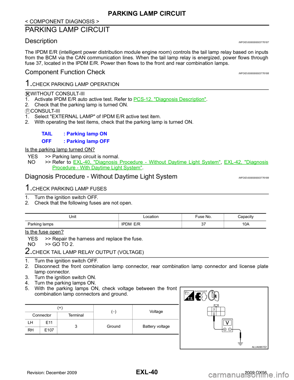
2.CHECK TAIL LAMP RELAY OUTPUT (VOLTAGE)
1. Turn the ignition switch OFF.
2. Disconnect the front combination lamp connector, rear combination lamp connector and license plate
lamp connector.
3. Turn the ignition switch ON.
4. Turn the parking lamps ON.
5. With the parking lamps ON, check voltage between the front combination lamp connectors and ground.TAIL : Parking lamp ON
OFF : Parking lamp OFF
Unit
LocationFuse No.Capacity
Parking lamps IPDM E/R3710A
(+)
(−)V olt a ge
Connector Terminal
LH E11 3Ground Battery voltage
RH E107
ALLIA0857ZZ
Revision: December 20092009 QX56
Page 1990 of 4171

EXL-42
< COMPONENT DIAGNOSIS >
PARKING LAMP CIRCUIT
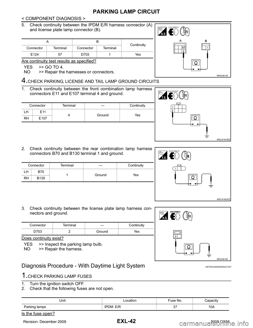
5. Check continuity between the IPDM E/R harness connector (A)and license plate lamp connector (B).
Are continuity test results as specified?
YES >> GO TO 4.
NO >> Repair the harnesses or connectors.
4.CHECK PARKING, LICENSE A ND TAIL LAMP GROUND CIRCUITS
1. Check continuity between the front combination lamp harness connectors E11 and E107 terminal 4 and ground.
2. Check continuity between the rear combination lamp harness connectors B70 and B130 terminal 1 and ground.
3. Check continuity between the license plate lamp harness con- nectors and ground.
Does continuity exist?
YES >> Inspect the parking lamp bulb.
NO >> Repair the harness.
Diagnosis Procedure - With Daytime Light SystemINFOID:0000000004221427
1.CHECK PARKING LAMP FUSES
1. Turn the ignition switch OFF.
2. Check that the following fuses are not open.
Is the fuse open?
AB Continuity
Connector Terminal Connector Terminal
E124 57D703 1Yes
WKIA4614E
Connector Terminal —Continuity
LH E11 4Ground Yes
RH E107
AWLIA1619ZZ
Connector Terminal —Continuity
LH B70 1Ground Yes
RH B130
AWLIA1624ZZ
Connector Terminal —Continuity
D703 2Ground Yes
WKIA4615E
Unit LocationFuse No.Capacity
Parking lamps IPDM E/R3710A
Revision: December 20092009 QX56
Page 2365 of 4171
![INFINITI QX56 2009 Factory Service Manual HAC-52
< COMPONENT DIAGNOSIS >[AUTOMATIC AIR CONDITIONER]
BLOWER MOTOR CONTROL SYSTEM
YES >> Refer to HAC-24, "A/C System Self-Diagnosis Code Chart".
NO >> GO TO 5.
5.PERFORM A/C AND AV SWITCH ASSEMB INFINITI QX56 2009 Factory Service Manual HAC-52
< COMPONENT DIAGNOSIS >[AUTOMATIC AIR CONDITIONER]
BLOWER MOTOR CONTROL SYSTEM
YES >> Refer to HAC-24, "A/C System Self-Diagnosis Code Chart".
NO >> GO TO 5.
5.PERFORM A/C AND AV SWITCH ASSEMB](/manual-img/42/57031/w960_57031-2364.png)
HAC-52
< COMPONENT DIAGNOSIS >[AUTOMATIC AIR CONDITIONER]
BLOWER MOTOR CONTROL SYSTEM
YES >> Refer to HAC-24, "A/C System Self-Diagnosis Code Chart".
NO >> GO TO 5.
5.PERFORM A/C AND AV SWITCH ASSEMBLY SELF-DIAGNOSIS
Perform self-diagnosis to check the A/C and AV switch assembly. Refer to HAC-23, "
A/C and AV Switch
Assembly Self-Diagnosis".
Is the inspection results normal?
YES >> GO TO 6.
NO >> Replace A/C and AV switch assembly. Refer to VTL-7, "
Removal and Installation".
6.CHECK BLOWER MOTOR OPERATION
Check and verify blower motor operates manually in all speeds.
Does blower motor operate in all speeds?
YES >> GO TO 7.
NO >> Refer to HAC-52, "
Front Blower Motor Diagnosis Procedure".
7.CHECK ENGINE COOLANT TE MPERATURE SENSOR CIRCUIT
Check engine coolant temperature sensor circuit. Refer to EC-121, "
Diagnosis Procedure".
Is the inspection results normal?
YES >> GO TO 8.
NO >> Replace enging coolant temperature sensor.
8.RECHECK FOR ANY SYMPTOMS
Perform a complete operational check for any symptoms. Refer to HAC-4, "
Operational Check (Front)".
Does another symptom exist?
YES >> Refer to HAC-3, "How to Perform Trouble Diagnosis For Quick And Accurate Repair" .
NO >> Replace A/C auto amp. Refer to VTL-7, "
Removal and Installation".
Front Blower Motor Diagnosis ProcedureINFOID:0000000003775358
SYMPTOM: Blower motor operation is malfunctioning.
DIAGNOSTIC PROCEDURE FOR BLOWER MOTOR
SYMPTOM: Blower motor operation is malfunctioning under starting
blower speed control.
1.CHECK FUSES
AWIIA0174GB
Revision: December 20092009 QX56
Page 2366 of 4171
![INFINITI QX56 2009 Factory Service Manual BLOWER MOTOR CONTROL SYSTEMHAC-53
< COMPONENT DIAGNOSIS > [AUTOMATIC AIR CONDITIONER]
C
D
E
F
G H
J
K L
M A
B
HAC
N
O P
Check 20A fuses [No. 24 and 27 (Located in the fuse and fusible link box)]. For INFINITI QX56 2009 Factory Service Manual BLOWER MOTOR CONTROL SYSTEMHAC-53
< COMPONENT DIAGNOSIS > [AUTOMATIC AIR CONDITIONER]
C
D
E
F
G H
J
K L
M A
B
HAC
N
O P
Check 20A fuses [No. 24 and 27 (Located in the fuse and fusible link box)]. For](/manual-img/42/57031/w960_57031-2365.png)
BLOWER MOTOR CONTROL SYSTEMHAC-53
< COMPONENT DIAGNOSIS > [AUTOMATIC AIR CONDITIONER]
C
D
E
F
G H
J
K L
M A
B
HAC
N
O P
Check 20A fuses [No. 24 and 27 (Located in the fuse and fusible link box)]. For fuse layout. Refer to PG-72,
"Terminal Arrangement".
Is the inspection result normal?
YES >> GO TO 2.
NO >> GO TO 7.
2.CHECK FRONT BLOWER MOTOR POWER SUPPLY CIRCUIT
1. Turn ignition switch OFF.
2. Disconnect front blower motor connector.
3. Turn ignition switch ON.
4. Press the A/C switch.
5. Press the front blower contro l "+" switch to maximum speed.
6. Check voltage between front blower motor harness connector
M62 terminal 2 and ground.
Is the inspection result normal?
YES >> GO TO 10.
NO >> GO TO 3.
3.CHECK FRONT BLOWER MOTOR RELAY (S WITCH SIDE) POWER SUPPLY CIRCUIT
1. Turn ignition switch OFF.
2. Disconnect front blower motor relay.
3. Check voltage between front blower motor relay harness con- nector M107 terminal 5 and ground.
Is the inspection result normal?
YES >> GO TO 4.
NO >> Repair harness or connector.
4.CHECK FRONT BLOWER MOTOR RELAY
Turn ignition switch OFF.
Check front blower motor relay. Refer to HAC-55, "
Front Blower Motor Component Inspection".
Is the inspection result normal?
YES >> GO TO 5.
NO >> Replace front blower motor relay.
5.CHECK FRONT BLOWER MOTOR RELA Y (SWITCH SIDE) CIRCUIT FOR OPEN
Check continuity between front bl ower motor relay harness connec-
tor M107 terminal 3 and front blower motor harness connector M62
terminal 2.
Is the inspection result normal?
YES >> GO TO 6.
NO >> Repair harness or connector.
6.CHECK FRONT BLOWER MOTOR RELAY (COIL SIDE) POWER SUPPLY Fuses are good.
2 - Ground
: Battery voltage
WJIA1331E
5 - Ground: Battery voltage
WJIA1886E
3 - 2 : Continuity should exist.
WJIA1360E
Revision: December 20092009 QX56
Page 2367 of 4171
![INFINITI QX56 2009 Factory Service Manual HAC-54
< COMPONENT DIAGNOSIS >[AUTOMATIC AIR CONDITIONER]
BLOWER MOTOR CONTROL SYSTEM
1. Turn ignition switch ON.
2. Check voltage between front blower motor relay harness con-
nector M107 terminal 2 INFINITI QX56 2009 Factory Service Manual HAC-54
< COMPONENT DIAGNOSIS >[AUTOMATIC AIR CONDITIONER]
BLOWER MOTOR CONTROL SYSTEM
1. Turn ignition switch ON.
2. Check voltage between front blower motor relay harness con-
nector M107 terminal 2](/manual-img/42/57031/w960_57031-2366.png)
HAC-54
< COMPONENT DIAGNOSIS >[AUTOMATIC AIR CONDITIONER]
BLOWER MOTOR CONTROL SYSTEM
1. Turn ignition switch ON.
2. Check voltage between front blower motor relay harness con-
nector M107 terminal 2 and ground.
Is the inspection result normal?
YES >> Repair front blower motor ground circuit or connector.
NO >> Repair harness or connector.
7.REPLACE FUSES
Replace fuses.
Does the fuse blow?
YES >> • If fuse blows without activating the front blower motor, repair short between fuse and front blower motor relay.
• If fuse blows activating the front blower motor, GO TO 8.
NO >> Inspection End.
8.CHECK FRONT BLOWER MOTOR POWER SUPPLY CIRCUIT FOR SHORT
1. Turn ignition switch OFF.
2. Disconnect front blower motor connector, front blower motor relay and variable blower control connector.
3. Check continuity between variable blower control harness con- nector M122 terminal 4 and ground.
Is the inspection result normal?
YES >> GO TO 9.
NO >> Repair harness or connector.
9.CHECK FRONT BLOWER MOTOR
Check front blower motor. Refer to HAC-55, "
Front Blower Motor Component Inspection".
Is the inspection result normal?
YES >> Replace variable blower control (front). Refer to VTL-29, "Removal and Installation".
NO >> Replace front blower motor. Refer to VTL-12, "
Removal and Installation".
10.CHECK FRONT BLOWER MOTOR
Check front blower motor. Refer to HAC-55, "
Front Blower Motor Component Inspection".
Is the inspection result normal?
YES >> GO TO 11.
NO >> Replace front blower motor. Refer to VTL-12, "
Removal and Installation".
11 .CHECK BLOWER MOTOR GROUND CIRCUIT
1. Disconnect variable blower control connector.
2. Check continuity between front blower motor harness connector M62 (B) terminal 1 and variable blower control harness connec-
tor M122 (A) terminal 2.
Is the inspection result normal?
YES >> GO TO 12.
NO >> Repair harness or connector. 2 - Ground
: Battery voltage
WJIA1363E
4 - Ground: Continuity should not exist.
AWIIA0177ZZ
1 - 2 : Continuity should exist.
AWIIA0179ZZ
Revision: December 20092009 QX56
Page 2371 of 4171
![INFINITI QX56 2009 Factory Service Manual HAC-58
< COMPONENT DIAGNOSIS >[AUTOMATIC AIR CONDITIONER]
BLOWER MOTOR CONTROL SYSTEM
NO >> • Check the rear air control (rear). Refer to
HAC-59, "Rear Air Control (Rear) Diagnosis Proce-
dure #2". INFINITI QX56 2009 Factory Service Manual HAC-58
< COMPONENT DIAGNOSIS >[AUTOMATIC AIR CONDITIONER]
BLOWER MOTOR CONTROL SYSTEM
NO >> • Check the rear air control (rear). Refer to
HAC-59, "Rear Air Control (Rear) Diagnosis Proce-
dure #2".](/manual-img/42/57031/w960_57031-2370.png)
HAC-58
< COMPONENT DIAGNOSIS >[AUTOMATIC AIR CONDITIONER]
BLOWER MOTOR CONTROL SYSTEM
NO >> • Check the rear air control (rear). Refer to
HAC-59, "Rear Air Control (Rear) Diagnosis Proce-
dure #2".
4.RECHECK FOR ANY SYMPTOMS
Perform a complete operational check for any symptoms. Refer to HAC-5, "
Operational Check (Rear)".
Does another symptom exist?
YES >> Refer to HAC-3, "How to Perform Trouble Diagnosis For Quick And Accurate Repair".
NO >> Inspection End.
Rear Air Control (Front) Diagnosis Procedure #1INFOID:0000000003775362
REAR BLOWER MOTOR INOPERATIVE/ON AT ALL TIMES.
1.CHECK FUSES
Check 10A fuse [No. 19 (Located in the fuse block J/B)].
Is the inspection result normal?
YES >> GO TO 2.
NO >> GO TO 6.
2.CHECK REAR AIR CONTRO L (FRONT) POWER SUPPLY
1. Disconnect rear air control (front) harness connector.
2. Turn ignition switch ON.
3. Check voltage between rear air control (front) harness connec- tor R108 terminal 1 and ground.
Is the inspection result normal?
YES >> GO TO 3.
NO >> Repair harness or connector.
3.CHECK REAR AIR CONTROL (FRONT) LIN BUS VOLTAGE
Check voltage between rear air control (front) harness connector
R108 terminal 5 and ground.
Is the inspection result normal?
YES >> GO TO 4.
NO >> Repair harness or connector.
4.CHECK REAR AIR CONTRO L (FRONT) GROUND CIRCUIT
Fuse is good.
Battery voltage should exist.
AWIIA0182ZZ
Battery voltage should exist.
AWIIA0183ZZ
Revision: December 20092009 QX56
Page 2403 of 4171
![INFINITI QX56 2009 Factory Service Manual HAC-90
< COMPONENT DIAGNOSIS >[AUTOMATIC AIR CONDITIONER]
POWER SUPPLY AND GROUND
CIRCUIT FOR CONTROLLER
Check main power supply and ground circuit. Refer to HAC-90, "A/C Auto Amp Power and Ground D INFINITI QX56 2009 Factory Service Manual HAC-90
< COMPONENT DIAGNOSIS >[AUTOMATIC AIR CONDITIONER]
POWER SUPPLY AND GROUND
CIRCUIT FOR CONTROLLER
Check main power supply and ground circuit. Refer to HAC-90, "A/C Auto Amp Power and Ground D](/manual-img/42/57031/w960_57031-2402.png)
HAC-90
< COMPONENT DIAGNOSIS >[AUTOMATIC AIR CONDITIONER]
POWER SUPPLY AND GROUND
CIRCUIT FOR CONTROLLER
Check main power supply and ground circuit. Refer to HAC-90, "A/C Auto Amp Power and Ground Diagnosis
Procedure".
Is the inspection result normal?
YES >> System OK.
NO >> Replace A/C auto amp. Refer to VTL-7, "
Removal and Installation".
A/C Auto Amp Power and Ground Diagnosis ProcedureINFOID:0000000003775387
DIAGNOSTIC PROCEDURE FOR A/C SYSTEM
SYMPTOM: A/C system does not come on.
1. CHECK POWER SUPPLY CIRCUITS FOR A/C AUTO AMP.
1. Turn ignition switch ON.
2. Check voltage between A/C auto amp. harness connector M49 (B) terminal 15 and M50 (A) terminal 27, and ground.
Is the inspection result normal?
YES >> GO TO 2.
NO >> Check 10A fuses [Nos. 8 and 19, located in the fuse block (J/B)]. Refer to PG-72, "
Terminal
Arrangement".
• If fuses are OK, check harness for open circuit. Repair or replace as necessary.
• If fuses are NG, replace fuse and check harness fo r short circuit. Repair or replace as neces-
sary.
2. CHECK GROUND CIRCUIT FOR A/C AUTO AMP.
1. Turn ignition switch OFF.
2. Disconnect A/C auto amp. connectors.
3. Check continuity between A/C auto amp. harness connector M50 terminal 36 and ground.
Is the inspection result normal?
OK >> Replace A/C auto amp. Refer to VTL-7, "Removal and
Installation".
NG >> Repair harness or connector.
AWIIA0212GB
Terminals Ignition switch position
(+)
(-) OFF ACC ON
A/C auto
amp. con- nector Te r m i n a l N o .
M49 15 GroundApprox. 0V Approx. 0V
Battery
voltage
M50 27 Battery
voltage Battery
voltage Battery
voltage
AWIIA1073ZZ
36 - Ground : Continuity should exist.
AWIIA0214ZZ
Revision: December 20092009 QX56