Page 3435 of 4171

SN
POWER SUPPLY AND GROUND CIRCUITSN-13
< COMPONENT DIAGNOSIS >
C
DE
F
G H
I
J
K L
M B A
O P
COMPONENT DIAGNOSIS
POWER SUPPLY AND GROUND CIRCUIT
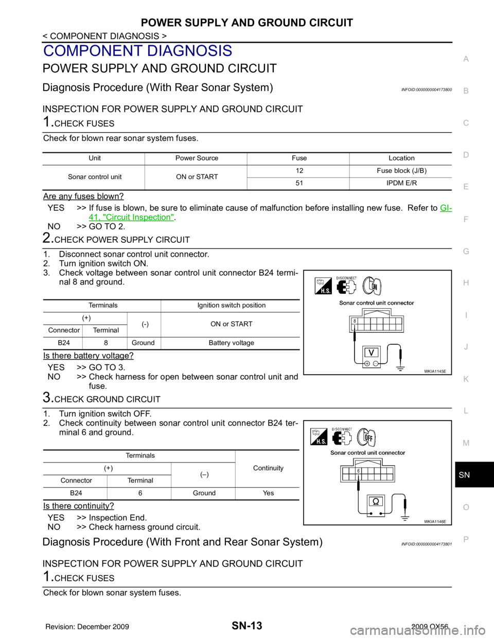
Diagnosis Procedure (With Rear Sonar System)INFOID:0000000004173800
INSPECTION FOR POWER SUPPLY AND GROUND CIRCUIT
1.CHECK FUSES
Check for blown rear sonar system fuses.
Are any fuses blown?
YES >> If fuse is blown, be sure to eliminate cause of malfunction before installing new fuse. Refer to GI-
41, "Circuit Inspection".
NO >> GO TO 2.
2.CHECK POWER SUPPLY CIRCUIT
1. Disconnect sonar control unit connector.
2. Turn ignition switch ON.
3. Check voltage between sonar control unit connector B24 termi- nal 8 and ground.
Is there battery voltage?
YES >> GO TO 3.
NO >> Check harness for open between sonar control unit and fuse.
3.CHECK GROUND CIRCUIT
1. Turn ignition switch OFF.
2. Check continuity between sonar control unit connector B24 ter- minal 6 and ground.
Is there continuity?
YES >> Inspection End.
NO >> Check harness ground circuit.
Diagnosis Procedure (With Front and Rear Sonar System)INFOID:0000000004173801
INSPECTION FOR POWER SUPPLY AND GROUND CIRCUIT
1.CHECK FUSES
Check for blown sonar system fuses.
Unit Power Source FuseLocation
Sonar control unit ON or START 12
Fuse block (J/B)
51 IPDM E/R
Terminals Ignition switch position
(+) (-) ON or START
Connector Terminal
B24 8 Ground Battery voltage
WKIA1145E
Te r m i n a l s
Continuity
(+)
(–)
Connector Terminal
B24 6 Ground Yes
WKIA1146E
Revision: December 20092009 QX56
Page 3436 of 4171

SN-14
< COMPONENT DIAGNOSIS >
POWER SUPPLY AND GROUND CIRCUIT
Are any fuses blown?
YES >> If fuse is blown, be sure to eliminate cause of malfunction before installing new fuse. Refer to GI-
41, "Circuit Inspection".
NO >> GO TO 2.
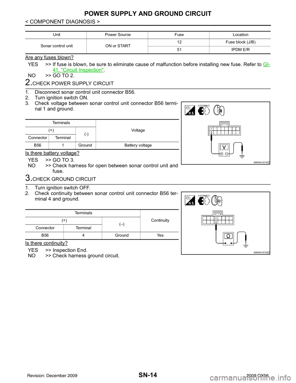
2.CHECK POWER SUPPLY CIRCUIT
1. Disconnect sonar control unit connector B56.
2. Turn ignition switch ON.
3. Check voltage between sonar control unit connector B56 termi- nal 1 and ground.
Is there battery voltage?
YES >> GO TO 3.
NO >> Check harness for open between sonar control unit and fuse.
3.CHECK GROUND CIRCUIT
1. Turn ignition switch OFF.
2. Check continuity between sonar control unit connector B56 ter-
minal 4 and ground.
Is there continuity?
YES >> Inspection End.
NO >> Check harness ground circuit.
Unit Power Source FuseLocation
Sonar control unit ON or START 12
Fuse block (J/B)
51 IPDM E/R
Te r m i n a l s
Vo l ta g e
(+)
(-)
Connector Terminal
B56 1 Ground Battery voltage
AWNIA1574ZZ
Te r m i n a l s
Continuity
(+)
(–)
Connector Terminal
B56 4Ground Yes
AWNIA1575ZZ
Revision: December 20092009 QX56
Page 3992 of 4171

WCS
POWER SUPPLY AND GROUND CIRCUITWCS-15
< COMPONENT DIAGNOSIS >
C
DE
F
G H
I
J
K L
M B A
O P
COMPONENT DIAGNOSIS
POWER SUPPLY AND GROUND CIRCUIT
COMBINATION METER
COMBINATION METER : Diagnosis ProcedureINFOID:0000000004115459
1.CHECK FUSES
Check for blown combination meter fuses.
Is the inspection result normal?
YES >> GO TO 2
NO >> If fuse is blown, be sure to eliminate cause of malfunction before installing new fuse.
2.POWER SUPPLY CIRCUIT CHECK
1. Disconnect combination meter connector M24.
2. Check voltage between combination meter harness connector M24 terminals 21, 37, 40 and ground.
Is the inspection result normal?
YES >> GO TO 3
NO >> Check harness for open between combination meter and fuse.
3.GROUND CIRCUIT CHECK
1. Turn ignition switch OFF.
2. Disconnect combination meter connector M23.
3. Check continuity between combination meter harness connector M23 terminal 47, 52 and ground, and connector M24 terminal 20
and ground.
Is the inspection result normal?
YES >> Inspection End.
NO >> Check ground harness.
Unit Power source Fuse No.
Combination meter Battery 19
Ignition switch ON or START 14
Ignition switch ACC or ON 4
TerminalsIgnition switch position
(+) (–) OFF ACC ON START
Connector Terminal
M24 21
Ground 0V 0V
Battery
voltage Battery
voltage
37 0VBattery
voltage Battery
voltage 0V
40 Battery
voltage Battery
voltage Battery
voltage Battery
voltage
AWNIA0204ZZ
Te r m i n a l s
Continuity
(+)
(–)
Connector Terminal
A: M23 47
Ground Yes
52
B: M24 20
AWNIA0205ZZ
Revision: December 20092009 QX56
Page 3993 of 4171

WCS-16
< COMPONENT DIAGNOSIS >
POWER SUPPLY AND GROUND CIRCUIT
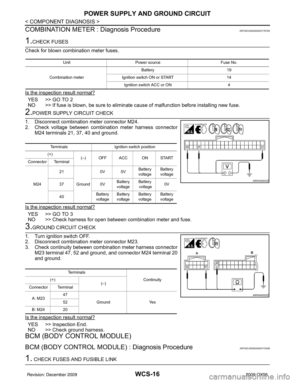
COMBINATION METER : Diagnosis Procedure
INFOID:0000000003776706
1.CHECK FUSES
Check for blown combination meter fuses.
Is the inspection result normal?
YES >> GO TO 2
NO >> If fuse is blown, be sure to eliminate cause of malfunction before installing new fuse.
2.POWER SUPPLY CIRCUIT CHECK
1. Disconnect combination meter connector M24.
2. Check voltage between combination meter harness connector M24 terminals 21, 37, 40 and ground.
Is the inspection result normal?
YES >> GO TO 3
NO >> Check harness for open between combination meter and fuse.
3.GROUND CIRCUIT CHECK
1. Turn ignition switch OFF.
2. Disconnect combination meter connector M23.
3. Check continuity between combination meter harness connector M23 terminal 47, 52 and ground, and connector M24 terminal 20
and ground.
Is the inspection result normal?
YES >> Inspection End.
NO >> Check ground harness.
BCM (BODY CONTROL MODULE)
BCM (BODY CONTROL MODULE) : Diagnosis ProcedureINFOID:0000000004115458
1. CHECK FUSES AND FUSIBLE LINK
Unit Power source Fuse No.
Combination meter Battery 19
Ignition switch ON or START 14
Ignition switch ACC or ON 4
TerminalsIgnition switch position
(+) (–) OFF ACC ON START
Connector Terminal
M24 21
Ground 0V 0V
Battery
voltage Battery
voltage
37 0VBattery
voltage Battery
voltage 0V
40 Battery
voltage Battery
voltage Battery
voltage Battery
voltage
AWNIA0204ZZ
Te r m i n a l s
Continuity
(+)
(–)
Connector Terminal
A: M23 47
Ground Yes
52
B: M24 20
AWNIA0205ZZ
Revision: December 20092009 QX56
Page 3994 of 4171

WCS
POWER SUPPLY AND GROUND CIRCUITWCS-17
< COMPONENT DIAGNOSIS >
C
DE
F
G H
I
J
K L
M B A
O P
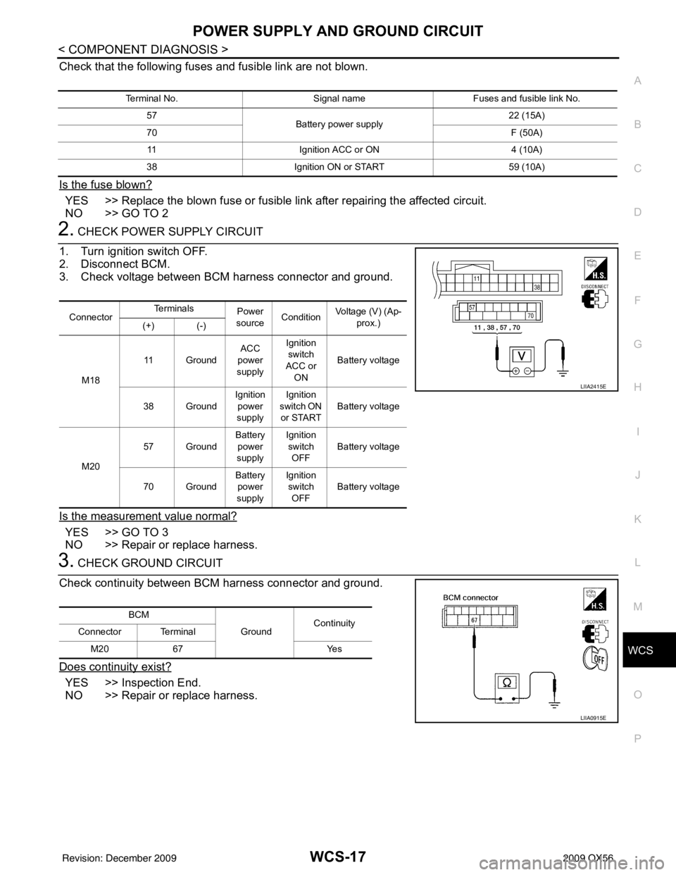
Check that the following fuses and fusible link are not blown.
Is the fuse blown?
YES >> Replace the blown fuse or fusible link after repairing the affected circuit.
NO >> GO TO 2
2. CHECK POWER SUPPLY CIRCUIT
1. Turn ignition switch OFF.
2. Disconnect BCM.
3. Check voltage between BCM harness connector and ground.
Is the measurement value normal?
YES >> GO TO 3
NO >> Repair or replace harness.
3. CHECK GROUND CIRCUIT
Check continuity between BCM harness connector and ground.
Does continuity exist?
YES >> Inspection End.
NO >> Repair or replace harness.
Terminal No. Signal nameFuses and fusible link No.
57 Battery power supply 22 (15A)
70 F (50A)
11 Ignition ACC or ON 4 (10A)
38 Ignition ON or START 59 (10A)
ConnectorTe r m i n a l s
Power
source Condition Voltage (V) (Ap-
prox.)
(+) (-)
M18 11 Ground
ACC
power
supply Ignition
switch
ACC or ON Battery voltage
38 Ground Ignition
power
supply Ignition
switch ON
or START Battery voltage
M20 57 Ground
Battery
power
supply Ignition
switch OFF Battery voltage
70 Ground Battery
power
supply Ignition
switch OFF Battery voltage
LIIA2415E
BCM
GroundContinuity
Connector Terminal
M20 67 Yes
LIIA0915E
Revision: December 20092009 QX56
Page 4105 of 4171
WW-18
< COMPONENT DIAGNOSIS >
WIPER AND WASHER FUSE
COMPONENT DIAGNOSIS
WIPER AND WASHER FUSE
DescriptionINFOID:0000000003776288
Fuse list
Diagnosis ProcedureINFOID:0000000003776289
1. CHECK FUSES
Check that the following fuses are not blown.
Is the fuse blown?
YES >> Replace the fuse after repairing the applicable circuit.
NO >> The fuse is normal.
Unit LocationFuse No. Capacity
Front wiper motor IPDM E/R3930 A
Front and rear washer motor Fuse block (J/B)910 A
Unit LocationFuse No. Capacity
Front wiper motor IPDM E/R3930 A
Front and rear washer motor Fuse block (J/B)910 A
Revision: December 20092009 QX56