2009 INFINITI QX56 Abs
[x] Cancel search: AbsPage 2189 of 4171
KNUCKLEFSU-19
< REMOVAL AND INSTALLATION >
C
DF
G H
I
J
K L
M A
B
FSU
N
O P
KNUCKLE
Removal and InstallationINFOID:0000000003772279
REMOVAL
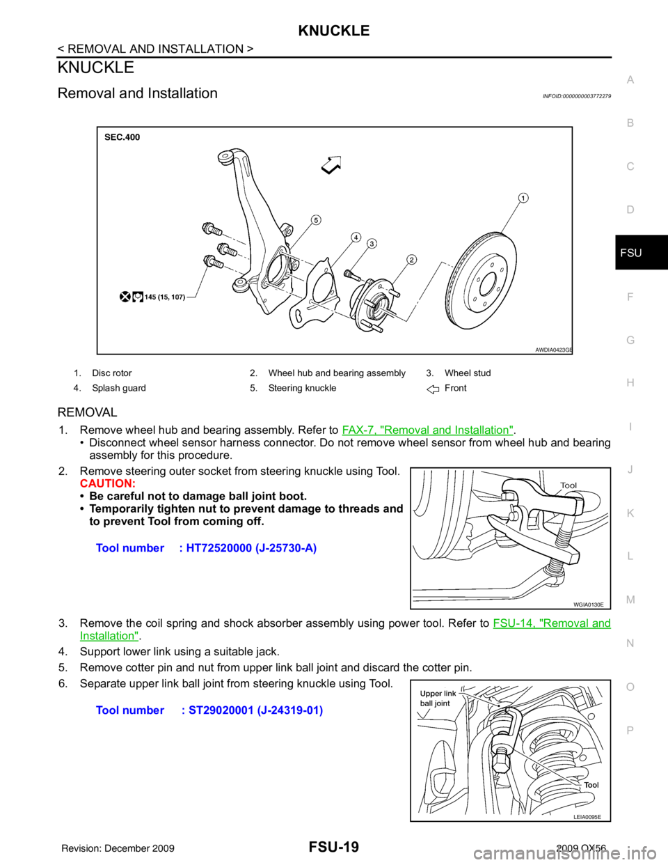
1. Remove wheel hub and bearing assembly. Refer to FAX-7, "Removal and Installation".
• Disconnect wheel sensor harness connector. Do not remove wheel sensor from wheel hub and bearing
assembly for this procedure.
2. Remove steering outer socket from steering knuckle using Tool. CAUTION:
• Be careful not to damage ball joint boot.
• Temporarily tighten nut to prevent damage to threads andto prevent Tool from coming off.
3. Remove the coil spring and shock absorber assembly using power tool. Refer to FSU-14, "
Removal and
Installation".
4. Support lower link using a suitable jack.
5. Remove cotter pin and nut from upper link ball joint and discard the cotter pin.
6. Separate upper link ball joint from steering knuckle using Tool.
1. Disc rotor 2. Wheel hub and bearing assembly 3. Wheel stud
4. Splash guard 5. Steering knuckle Front
AWDIA0423GB
Tool number : HT72520000 (J-25730-A)
WGIA0130E
Tool number : ST29020001 (J-24319-01)
LEIA0095E
Revision: December 20092009 QX56
Page 2191 of 4171
COIL SPRING AND SHOCK ABSORBERFSU-21
< DISASSEMBLY AND ASSEMBLY >
C
DF
G H
I
J
K L
M A
B
FSU
N
O P
DISASSEMBLY AND ASSEMBLY
COIL SPRING AN D SHOCK ABSORBER
Disassembly and AssemblyINFOID:0000000003772280
DISASSEMBLY
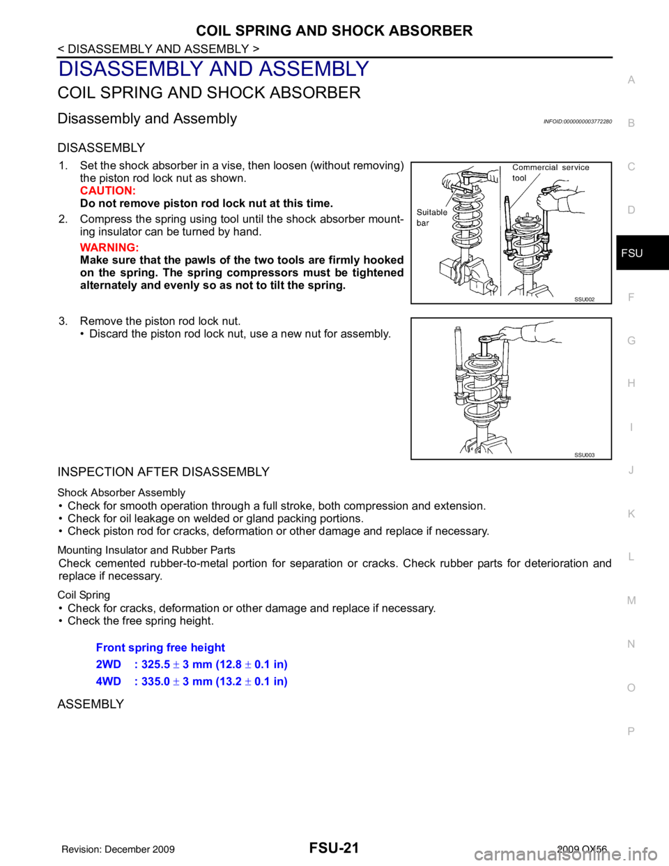
1. Set the shock absorber in a vise, then loosen (without removing)
the piston rod lock nut as shown.
CAUTION:
Do not remove piston rod lock nut at this time.
2. Compress the spring using tool until the shock absorber mount- ing insulator can be turned by hand.
WARNING:
Make sure that the pawls of the two tools are firmly hooked
on the spring. The spring compressors must be tightened
alternately and evenly so as not to tilt the spring.
3. Remove the piston rod lock nut. • Discard the piston rod lock nut, use a new nut for assembly.
INSPECTION AFTER DISASSEMBLY
Shock Absorber Assembly
• Check for smooth operation through a full stroke, both compression and extension.
• Check for oil leakage on welded or gland packing portions.
• Check piston rod for cracks, deformation or other damage and replace if necessary.
Mounting Insulator and Rubber Parts
Check cemented rubber-to-metal portion for separation or cracks. Check rubber parts for deterioration and
replace if necessary.
Coil Spring
• Check for cracks, deformation or other damage and replace if necessary.
• Check the free spring height.
ASSEMBLY
SSU002
SSU003
Front spring free height
2WD : 325.5 ± 3 mm (12.8 ± 0.1 in)
4WD : 335.0 ± 3 mm (13.2 ± 0.1 in)
Revision: December 20092009 QX56
Page 2192 of 4171
FSU-22
< DISASSEMBLY AND ASSEMBLY >
COIL SPRING AND SHOCK ABSORBER
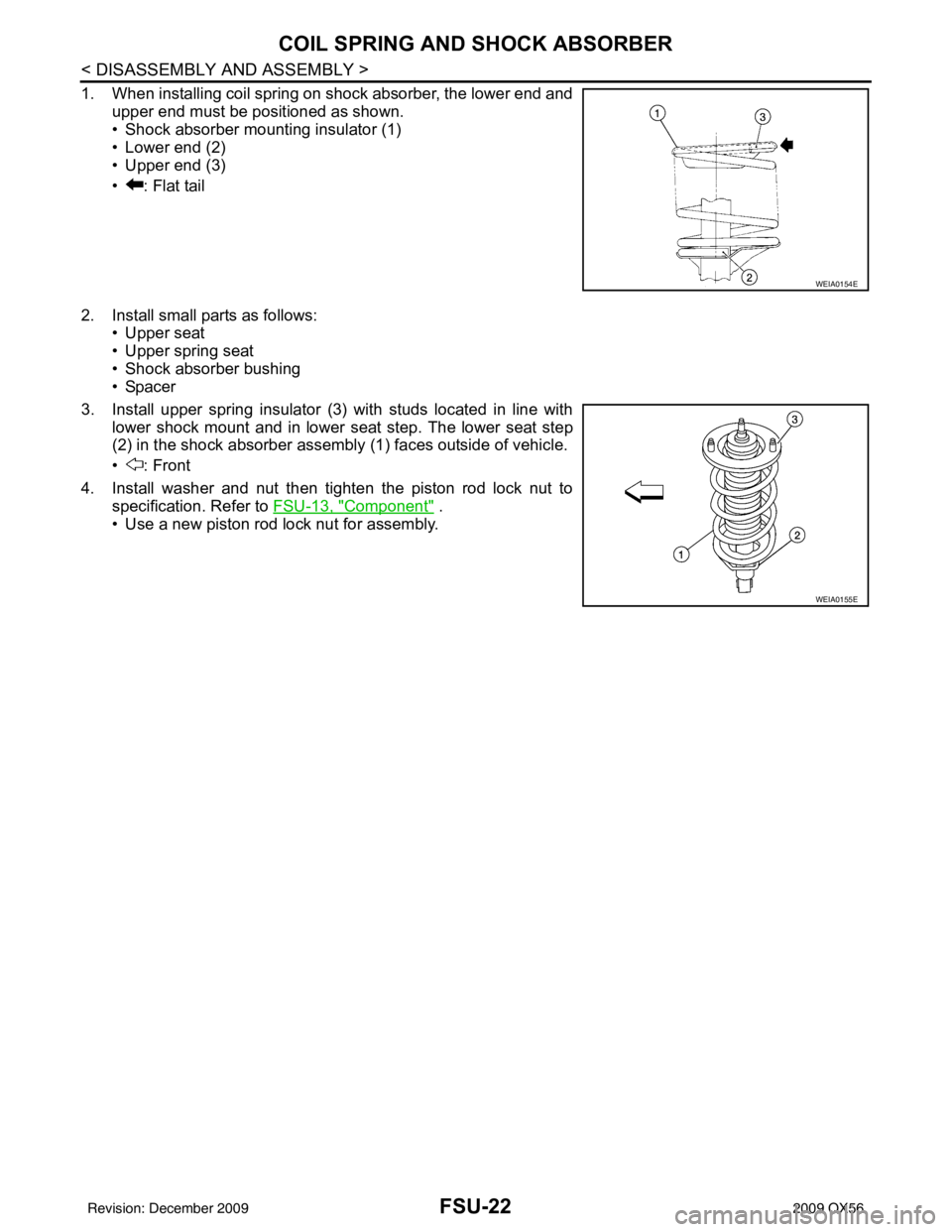
1. When installing coil spring on shock absorber, the lower end andupper end must be positioned as shown.
• Shock absorber mounting insulator (1)
• Lower end (2)
• Upper end (3)
•: Flat tail
2. Install small parts as follows: • Upper seat
• Upper spring seat
• Shock absorber bushing
• Spacer
3. Install upper spring insulator (3) with studs located in line with lower shock mount and in lower seat step. The lower seat step
(2) in the shock absorber assembly (1) faces outside of vehicle.
• : Front
4. Install washer and nut then tighten the piston rod lock nut to specification. Refer to FSU-13, "
Component" .
• Use a new piston rod lock nut for assembly.
WEIA0154E
WEIA0155E
Revision: December 20092009 QX56
Page 2193 of 4171
SERVICE DATA AND SPECIFICATIONS (SDS)FSU-23
< SERVICE DATA AND SPECIFICATIONS (SDS)
C
DF
G H
I
J
K L
M A
B
FSU
N
O P
SERVICE DATA AND SPECIFICATIONS (SDS)
SERVICE DATA AND SPECIFICATIONS (SDS)
General SpecificationINFOID:0000000003772281
Spring Free HeightINFOID:0000000003772282
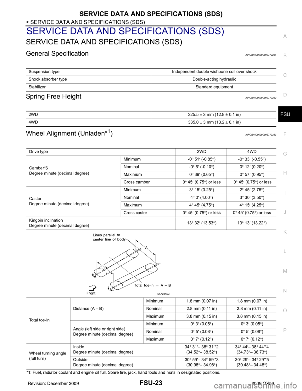
Wheel Alignment (Unladen*1)INFOID:0000000003772283
*1: Fuel, radiator coolant and engine oil full. Spare tire, jack, hand tools and mats in designated positions. Suspension type
Independent double wishbone coil over shock
Shock absorber type Double-acting hydraulic
Stabilizer Standard equipment
2WD325.5 ± 3 mm (12.8 ± 0.1 in)
4WD 335.0 ± 3 mm (13.2 ± 0.1 in)
Drive type 2WD 4WD
Camber*6
Degree minute (decimal degree) Minimum
-0° 51 ′ (-0.85 °)- 0° 33 ′ (-0.55 °)
Nominal -0° 6 ′ (-0.10 °)0 ° 12 ′ (0.20 °)
Maximum 0° 39 ′ (0.65 °)0 ° 57 ′ (0.95 °)
Cross camber 0° 45 ′ (0.75 °) or less 0 ° 45′ (0.75 °) or less
Caster
Degree minute (decimal degree) Minimum
3° 15 ′ (3.25 °)2 ° 45 ′ (2.75 °)
Nominal 4° 0 ′ (4.00 °)3 ° 30 ′ (3.50 °)
Maximum 4° 45 ′ (4.75 °)4 ° 15 ′ (4.25 °)
Cross caster 0° 45 ′ (0.75 °) or less 0
° 45 ′ (0
.75°) or less
Kingpin inclination
Degree minute (decimal degree) 13
° 32 ′ (13.53 °)1 3° 13 ′ (13.22 °)
Total toe-in Distance (A
− B) Minimum
1.8 mm (0.07 in) 1.8 mm (0.07 in)
Nominal 2.8 mm (0.11 in) 2.8 mm (0.11 in)
Maximum 3.8 mm (0.15 in) 3.8 mm (0.15 in)
Angle (left side or right side)
Degree minute (decimal degree) Minimum
0° 3 ′ (0.05 °)0 ° 3 ′ (0.05 °)
Nominal 0° 5 ′ (0.08 °)0 ° 5 ′ (0.08 °)
Maximum 0° 7 ′ (0.12 °)0 ° 7 ′ (0.12 °)
Wheel turning angle
(full turn) Inside
Degree minute (decimal degree)
34
° 31 ′– 38 ° 31 ′*2
(34.52 °– 38.52° ) 34
° 44 ′– 38° 44′*4
(34.73 °– 38.73 °)
Ou t
side
Degree minute (decimal degree) 30
° 59 ′– 34 ° 59 ′*3
(30.98 °– 34.98° ) 30
° 29 ′– 34° 29′*5
(30.48 °– 34.48 °)
SFA234AC
Revision: December 20092009 QX56
Page 2211 of 4171

TERMINOLOGYGI-17
< HOW TO USE THIS MANUAL >
C
DE
F
G H
I
J
K L
M B
GI
N
O P
Exhaust gas recirculation control-BPT
valve EGRC-BPT valve
BPT valve
Exhaust gas recirculation control-solenoid
valve EGRC-solenoid valve
EGR control solenoid valve
Exhaust gas recirculation temperature sen-
sor EGRT sensorExhaust gas temperature sensor
EGR temperature sensor
Flash electrically erasable programmable
read only memory FEEPROM
***
Flash erasable programmable read only
memory FEPROM
***
Flexible fuel sensor FFS***
Flexible fuel system FF system***
Fuel pressure regulato r*** Pressure regulator
Fuel pressure regulator control solenoid
valve ***
PRVR control solenoid valve
Fuel trim FT***
Heated Oxygen sensor HO2S Exhaust gas sensor
Idle air control system IAC system Idle speed control
Idle air control valve-air regulato rIACV-air regulator Air regulator
Idle air control valve-auxiliary air control
valve IACV-AAC valve
Auxiliary air control (AAC) valve
Idle air control valve-FICD solenoid valve IACV-FICD solenoid valve FICD solenoid valve
Idle air control valve-idle up control sole-
noid valve IACV-idle up control solenoid valve Idle up control solenoid valve
Idle speed control-FI pot ISC-FI pot FI pot
Idle speed control system ISC system***
Ignition control IC***
Ignition control module ICM***
Indirect fuel injection system IFI system ***
Intake air IA Air
Intake air temperature sensor IAT sensor Air temperature sensor
Knock *** Detonation
Knock sensor KS Detonation sensor
Malfunction indicator lamp MIL Check engine light
Manifold absolute pressure MAP ***
Manifold absolute pressure sensor MAPS ***
Manifold differential pressure MDP ***
Manifold differential pressure sensor MDPS ***
Manifold su rface temperature MST ***
Manifold surface temperature sensor MSTS ***
Manifold vacuum zone MVZ ***
Manifold vacuum zone sensor MVZS***
Mass air flow sensor MAFS Air flow meter
Mixture control solenoid valve MC solenoid valveAir-fuel ratio control solenoid valve
Multiport fuel injection System MFI system Fuel injection control
NEW TERM
NEW ACRONYM /
ABBREVIATION OLD TERM
Revision: December 20092009 QX56
Page 2215 of 4171
IDENTIFICATION INFORMATIONGI-21
< FEATURES OF NEW MODEL >
C
DE
F
G H
I
J
K L
M B
GI
N
O P
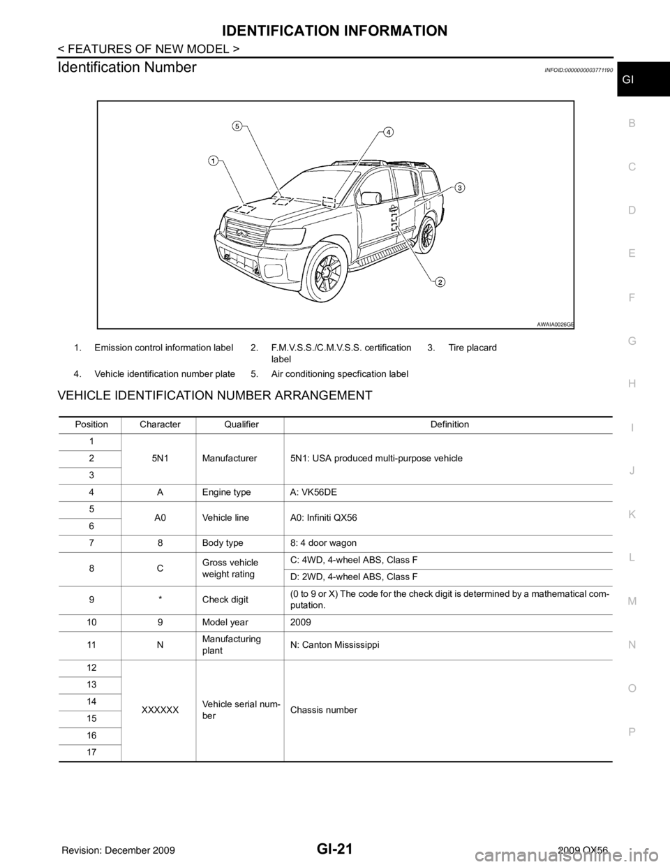
Identification NumberINFOID:0000000003771190
VEHICLE IDENTIFICATION NUMBER ARRANGEMENT
1. Emission control information label 2. F.M.V.S.S./C.M.V.S.S. certification label 3. Tire placard
4. Vehicle identification number plate 5. Air conditioning specfication label
AWAIA0026GB
Position Character Qualifier Definition
1 5N1 Manufacturer 5N1: USA produced multi-purpose vehicle
2
3
4 A Engine type A: VK56DE
5 A0 Vehicle line A0: Infiniti QX56
6
7 8 Body type 8: 4 door wagon
8C Gross vehicle
weight ratingC: 4WD, 4-wheel ABS, Class F
D: 2WD, 4-wheel ABS, Class F
9 * Check digit (0 to 9 or X) The code for the check digit is determined by a mathematical com-
putation.
10 9 Model year 2009
11 NManufacturing
plant
N: Canton Mississippi
12
XXXXXX Vehicle serial num-
ber Chassis number
13
14
15
16
17
Revision: December 20092009 QX56
Page 2240 of 4171
GI-46
< BASIC INSPECTION >
CONSULT-III CHECKING SYSTEM
CONSULT-III CHECKING SYSTEM
DescriptionINFOID:0000000003771217
• When CONSULT-III is connected with a data link connectorequipped on the vehicle side, it will communicate with the control
unit equipped in the vehicle and then enable various kinds of diag-
nostic tests.
• Refer to “CONSULT-III Operation Manual” for more information.
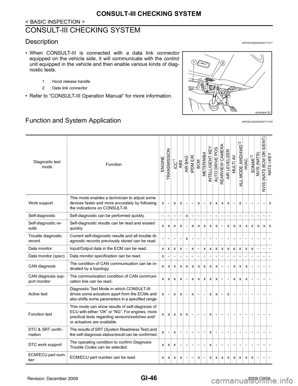
Function and System ApplicationINFOID:0000000003771218
1 : Hood release handle
2 : Data link connector
ALBIA0047ZZ
Diagnostic test mode Function
ENGINE
TRANSMISSION
ICC
*1
ABS
AIR BAG
IPDM E/R BCM
METER/M&A
INTELLIGENT KEY
AUTO DRIVE POS.
REARVIEW CAMERA AIR LEVELIZER MULTI AV
ALL MODE AWD/4WD
*2
HVAC
SONAR
*3
NVIS (NATS)
NVIS (NATS BCM OR S/ENT) NATS I-KEY
Work support This mode enables a technician to adjust some
devices faster and more accurately by following
the indications on CONSULT-III. x-xx--x-xxxx-x----x
Self-diagnostic Self-diagnostic can be performed quickly. ----x--------------
Self-diagnostic re-
sults Self-diagnostic results can be read and erased
quickly.
xxx x- xxxxx- xxx xxxxx
Trouble diagnostic
record Current self-diagnostic results and all trouble di-
agnostic records previously stored can be read.
--- - x--- - ----------
Data monitor Input/Output data in the ECM can be read. xxx x- x- xxxxxxx xx- - -
Data monitor (spec) Data monitor specification can be read. x------------------
CAN diagnosis The condition of CAN communication can be in-
dicated by a topology.
xxx xxxxxxx- - xx x- - - -
CAN diagnosis sup-
port monitor The communication condition of CAN communi-
cation line can be read.
xxx x- xxxxx- - xx x- - - -
Active test Diagnostic Test Mode
in which CONSULT-III
drives some actuators apart from the ECMs and
also shifts some parameters in a specified range. x-xx-x--xx-x-------
Function test This mode can show results of self-diagnosis of
ECU with either “OK” or “NG”. For engines, more
practical tests regarding sensors/switches and/
or actuators are available. xxxxx---x----------
DTC & SRT confir-
mation The results of SRT (System Readiness Test) and
the self-diagnosis status/result can be confirmed.
x-x-----x----------
DTC work support The operating condition to confirm Diagnosis
Trouble Codes can be selected. xxx-----x----------
ECM/ECU part num-
ber ECM/ECU part number can be read.
xxx x- - x- xxxxxx xx- - -
Revision: December 20092009 QX56
Page 2241 of 4171

CONSULT-III CHECKING SYSTEMGI-47
< BASIC INSPECTION >
C
DE
F
G H
I
J
K L
M B
GI
N
O P
x : Applicable
*1: With intelligent cruise control
*2: With 4-wheel drive
*3: With front and rear sonar system
CONSULT-III Data Link Connector (DLC) CircuitINFOID:0000000003771219
INSPECTION PROCEDURE
If the CONSULT-III cannot diagnose the sys tem properly, check the following items.
NOTE:
The CAN and DDL2 circuits from DLC pins 6, 7 and 14 may be connected to more than one system. A short in
any circuit connected to a control unit in one system may affect CONSULT-III access to other systems.
ECU discriminated
No.Classification number of a replacement ECU can
be read to prevent an incorrect ECU from being
installed.
----x--------------
Passenger Airbag Displays the STATUS (readiness) of the front
passenger air bag.
----x--------------
AV COMM monitor The condition of AV communication can be indi-
cated. ------------x------
Configuration Sets control module para
meters to match vehicle
options. ------x------------
Steering lock re-
lease The condition of steering lock release solenoid. -----------------x-
PIN read This mode shows the BCM-specific 5-digit code.-----------------x-
Control unit
initialization All registered ignition key IDs in NATS compo-
nents can be initialized and new IDs can be reg-
istered.
----------------x--
Diagnostic test
mode Function
ENGINE
TRANSMISSION
ICC
*1
ABS
AIR BAG
IPDM E/R BCM
METER/M&A
INTELLIGENT KEY
AUTO DRIVE POS.
REARVIEW CAMERA AIR LEVELIZER
MULTI AV
ALL MODE AWD/4WD
*2
HVAC
SONAR
*3
NVIS (NATS)
NVIS (NATS BCM OR S/ENT) NATS I-KEY
Symptom Check item
CONSULT-III cannot access
any system. • CONSULT-III DLC power supply circuit (Terminal 8) and ground circuit (Terminal 4)
CONSULT-III cannot access in-
dividual system. (Other sys-
tems can be accessed.) • Power supply and ground circuit for the control unit of the system (For detailed circuit, refer to wiring
diagram for each system.)
• Open or short circuit between the system and CONSULT-III DLC (For detailed circuit, refer to wiring diagram for each system.)
• Open or short circuit CAN communication line. Refer to LAN-14, "
Trouble Diagnosis Flow Chart".
Revision: December 20092009 QX56