2009 INFINITI QX56 oil type
[x] Cancel search: oil typePage 1536 of 4171
![INFINITI QX56 2009 Factory Service Manual
P0420, P0430 THREE WAY CATALYST FUNCTIONEC-209
< COMPONENT DIAGNOSIS > [VK56DE]
C
D
E
F
G H
I
J
K L
M A
EC
NP
O
OK >> GO TO 10.
NG >> GO TO 7.
7.CHECK FUNCTION OF
IGNITION COIL-II
1. Turn ignition s INFINITI QX56 2009 Factory Service Manual
P0420, P0430 THREE WAY CATALYST FUNCTIONEC-209
< COMPONENT DIAGNOSIS > [VK56DE]
C
D
E
F
G H
I
J
K L
M A
EC
NP
O
OK >> GO TO 10.
NG >> GO TO 7.
7.CHECK FUNCTION OF
IGNITION COIL-II
1. Turn ignition s](/manual-img/42/57031/w960_57031-1535.png)
P0420, P0430 THREE WAY CATALYST FUNCTIONEC-209
< COMPONENT DIAGNOSIS > [VK56DE]
C
D
E
F
G H
I
J
K L
M A
EC
NP
O
OK >> GO TO 10.
NG >> GO TO 7.
7.CHECK FUNCTION OF
IGNITION COIL-II
1. Turn ignition switch OFF.
2. Disconnect spark plug and connect a known-good spark plug.
3. Crank engine for about 3 seconds, and recheck whet her spark is generated between the spark plug and
the grounded metal portion.
OK or NG
OK >> GO TO 8.
NG >> Check ignition coil, power transistor and their circuits. Refer to EC-404, "Diagnosis Procedure"
.
8.CHECK SPARK PLUG
Check the initial spark plug for fouling, etc.
OK or NG
OK >> Replace malfunctioning spark plug(s) with standard type one(s). For spark plug type, refer to EM-16, "Removal
and Installation".
NG >> 1. Repair or clean spark plug. 2. GO TO 9.
9.CHECK FUNCTION OF IGNITION COIL-III
1. Reconnect the initial spark plugs.
2. Crank engine for about three seconds, and recheck whether spark is generated between the spark plug and the grounded portion.
OK or NG
OK >> INSPECTION END
NG >> Replace malfunctioning spark plug(s) with standard type one(s). For spark plug type, refer to EM-
16, "Removal and Installation".
10.CHECK FUEL INJECTOR
1. Turn ignition switch OFF.
2. Remove fuel injector assembly. Refer to EM-40, "Removal and Installation"
.
Keep fuel hose and all fuel injectors connected to fuel injector gallery.
3. Disconnect all ignition coil harness connectors.
4. Reconnect all fuel injector harness connectors disconnected.
5. Turn ignition switch ON. Make sure fuel does not drip from fuel injector.
OK or NG
OK (Does not drip.)>>GO TO 11.
NG (Drips.)>>Replace the fuel injector(s) from which fuel is dripping.
11 .CHECK INTERMITTENT INCIDENT
Refer to GI-35, "How to Check Terminal"
and GI-38, "Intermittent Incident".
Trouble is fixed.>> INSPECTION END
Trouble is not fixed.>>Replace three way catalyst assembly. Spark should be generated.
SEF156I
Spark should be generated.
Revision: December 20092009 QX56
Page 1824 of 4171
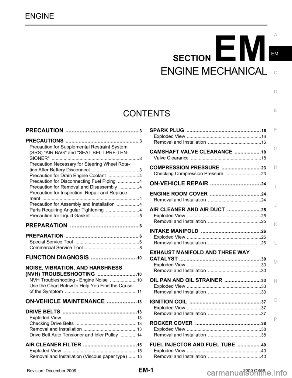
EM-1
ENGINE
C
DE
F
G H
I
J
K L
M
SECTION EM
A
EM
N
O P
CONTENTS
ENGINE MECHANICAL
PRECAUTION ....... ........................................3
PRECAUTIONS .............................................. .....3
Precaution for Supplemental Restraint System
(SRS) "AIR BAG" and "SEAT BELT PRE-TEN-
SIONER" ............................................................. ......
3
Precaution Necessary for Steering Wheel Rota-
tion After Battery Disconnect ............................... ......
3
Precaution for Drain Engine Coolant .........................4
Precaution for Disconnecting Fuel Piping .................4
Precaution for Removal and Disassembly ................4
Precaution for Inspection, Repair and Replace-
ment .................................................................... ......
4
Precaution for Assembly and Installation ..................4
Parts Requiring Angular Tightening ..........................4
Precaution for Liquid Gasket ............................... ......5
PREPARATION ............................................6
PREPARATION .............................................. .....6
Special Service Tool ........................................... ......6
Commercial Service Tool ..........................................8
FUNCTION DIAGNOSIS ..............................10
NOISE, VIBRATION, AND HARSHNESS
(NVH) TROUBLESHOOTING ........................ ....
10
NVH Troubleshooting - Engine Noise ................. ....10
Use the Chart Below to Help You Find the Cause
of the Symptom .......................................................
11
ON-VEHICLE MAINTENANCE ....................13
DRIVE BELTS ................................................ ....13
Exploded View .................................................... ....13
Checking Drive Belts ...............................................13
Removal and Installation .........................................13
Drive Belt Auto Tensioner and Idler Pulley ......... ....14
AIR CLEANER FILTER ......................................15
Exploded View .................................................... ....15
Removal and Installation (Viscous paper type) .......15
SPARK PLUG ...................................................16
Exploded View ..................................................... ....16
Removal and Installation .........................................16
CAMSHAFT VALVE CLEARANCE ..................18
Valve Clearance ......................................................18
COMPRESSION PRESSURE ...........................23
Checking Compression Pressure ............................23
ON-VEHICLE REPAIR .................................24
ENGINE ROOM COVER ...................................24
Removal and Installation ..................................... ....24
AIR CLEANER AND AIR DUCT .......................25
Exploded View .........................................................25
Removal and Installation .........................................25
INTAKE MANIFOLD .........................................26
Exploded View .........................................................26
Removal and Installation .........................................26
EXHAUST MANIFOLD AND THREE WAY
CATALYST ........................................................
30
Exploded View .........................................................30
Removal and Installation .........................................30
OIL PAN AND OIL STRAINER .........................33
Exploded View .........................................................33
Removal and Installation .........................................33
IGNITION COIL .................................................37
Exploded View .........................................................37
Removal and Installation .........................................37
ROCKER COVER .............................................38
Exploded View .........................................................38
Removal and Installation .........................................38
FUEL INJECTOR AND FUEL TUBE ................40
Exploded View .........................................................40
Removal and Installation .........................................40
Revision: December 20092009 QX56
Page 1834 of 4171
NOISE, VIBRATION, AND HARSHNESS (NVH) TROUBLESHOOTINGEM-11
< FUNCTION DIAGNOSIS >
C
DE
F
G H
I
J
K L
M A
EM
NP
O
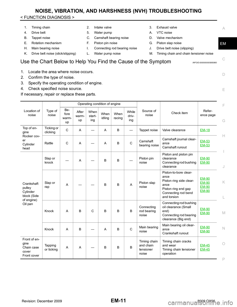
Use the Chart Below to Help You
Find the Cause of the SymptomINFOID:0000000005885860
1. Locate the area where noise occurs.
2. Confirm the type of noise.
3. Specify the operating condition of engine.
4. Check specified noise source.
If necessary, repair or replace these parts.
1. Timing chain 2. Intake valve3. Exhaust valve
4. Drive belt 5. Water pumpA. VTC noise
B. Tappet noise C. Camshaft bearing noiseD. Valve mechanism
E. Rotation mechanism F. Piston pin noise G. Piston slap noise
H. Main bearing noise I. Connecting rod bearing noise J. Drive belt noise (slipping)
K. Drive belt noise (stick/slipping) L. Water pump noise M. Timing chain and chain tensioner noise
Location of noise Ty p e o f
noise Operating condition of engine
Source of noise Check item Refer-
ence page
Be-
fore
warm-
up After
warm- up When
start- ing When
idling When
racing While
driv- ing
Top of en-
gine
Rocker cov-
er
Cylinder
head Ticking or
clicking
C A — A B — Tappet noise Valve clearance
EM-18
Rattle C A — A B CCamshaft
bearing noiseCamshaft journal clear-
ance
Camshaft runout EM-53EM-53
Crankshaft
pulley
Cylinder
block (Side
of engine)
Oil panSlap or
knock
—A—B B—
Piston pin
noisePiston and piston pin
clearance
Connecting rod bushing
clearance
EM-90
EM-90
Slap or
rap
A——B B A
Piston slap
noisePiston-to-bore clear-
ance
Piston ring side clear-
ance
Piston ring end gap
Connecting rod bend
and torsion EM-90EM-90
EM-90
EM-90
Knock A B C B B B
Connecting
rod bearing
noiseConnecting rod bushing
oil clearance (Small
end)
Connecting rod bearing
clearance (Big end)
EM-90EM-90
Knock A B — A B C
Main bearing
noiseMain bearing oil clear-
ance
Crankshaft runout EM-90EM-90
Front of en-
gine
Chain case
cover
Front coverTapping
or ticking
AA—BBB Timing chain
and chain
tensioner
noiseTiming chain cracks
and wear
Timing chain tensioner
operation
EM-45
EM-45
Revision: December 20092009 QX56
Page 1902 of 4171
ENGINE ASSEMBLYEM-79
< REMOVAL AND INSTALLATION >
C
DE
F
G H
I
J
K L
M A
EM
NP
O
1. Release the fuel pressure. Refer to
EC-487, "Fuel Pressure Check".
2. Drain the engine coolant. Refer to CO-11, "
Changing Engine Coolant".
3. Drain the engine oil. Refer to LU-9, "
Changing Engine Oil".
4. Disconnect the battery negative and positive terminal. Refer to PG-76, "
Removal and Installation".
5. Remove the engine hood. Refer to DLK-230, "
Removal and Installation of Hood Assembly".
6. Remove the cowl extension. Refer to EXT-18, "
Removal and Installation".
7. Remove the air duct and air cleaner case assembly. Refer to EM-25, "
Removal and Installation".
8. Remove the radiator assembly and hoses. Refer to CO-15, "
Removal and Installation".
NOTE:
To prevent possible A/T fluid drain from transmissi on opening, use appropriate cap to close off transmis-
sion opening during operation.
9. Remove the drive belt. Refer to EM-13, "
Removal and Installation".
10. Remove the fan blade. Refer to CO-18, "
Removal and Installation (Crankshaft Driven Type)".
11. Disconnect the engine room harness from the fuse box and set it aside.
12. Disconnect the ECM.
13. Disconnect the engine room harness from the engine side and set it aside.
14. Disconnect the engine harness grounds.
15. Disconnect the power steering reservoir t ank from the engine and move it aside.
16. Disconnect the power steering oil pump from the engine. Move it aside and secure it using suitable wire or rope. Refer to ST-26, "
Removal and Installation"
17. Remove the A/C compressor bolts and set the compressor aside. Refer to HA-31, "Removal and Installa-
tion for Compressor" (ATC).
18. Disconnect the brake booster vacuum hose.
19. Disconnect the EVAP line.
20. Disconnect the fuel hose at the engine side connection. Refer to EM-40, "
Removal and Installation".
21. Disconnect the heater hoses at the cowl, and in stall plugs to avoid leakage of engine coolant.
22. Remove the A/T oil level indicator and indicator tube upper bolts.
23. Remove the front final drive assembly (4WD only). Refer to DLN-215, "
Removal and Installation".
24. Remove the exhaust manifolds. Refer to EM-30, "
Removal and Installation".
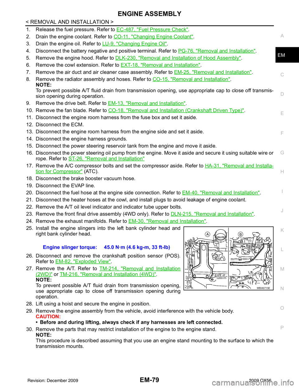
25. Install the engine slingers into the left bank cylinder head and right bank cylinder head.
26. Disconnect and remove the crankshaft position sensor (POS). Refer to EM-82, "
Exploded View".
27. Remove the A/T. Refer to TM-214, "
Removal and Installation
(2WD)" or TM-216, "Removal and Installation (4WD)".
NOTE:
To prevent possible A/T fluid drain from transmission opening,
use appropriate cap to close off transmission opening during
operation.
28. Lift using a hoist and secure the engine in position.
29. Remove the engine assembly from the vehicl e, avoid interference with the vehicle body.
CAUTION:
• Before and during lifting, always check if any harnesses are left connected.
30. Remove the parts that may restrict installation of the engine to the engine stand. NOTE:
This procedure is described assuming that you use an engine stand mounting to the surface to which the
transmission mounts. Engine slinger torque: 45.0 N·m (4.6 kg-m, 33 ft-lb)
WBIA0715E
Revision: December 20092009 QX56
Page 1906 of 4171
ENGINE UNITEM-83
< DISASSEMBLY AND ASSEMBLY >
C
DE
F
G H
I
J
K L
M A
EM
NP
O
Disassembly and AssemblyINFOID:0000000005885902
DISASSEMBLY
NOTE:
Explained here is how to disassemble with engine stand supporting transmission surface. When using differ-
ent type of engine stand, some steps may be different.
1. Remove engine assembly and mount to engine stand. Refer to
EM-78, "
Removal and Installation".
CAUTION:
Before removing the hanging chains, make sure engi ne stand is stable and there is no risk of over-
turning.
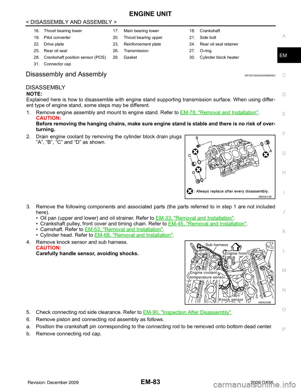
2. Drain engine coolant by removing the cylinder block drain plugs “A”, “B”, “C” and “D” as shown.
3. Remove the following components and associated parts (the parts referred to in step 1 are not included here).
• Oil pan (upper and lower) and oil strainer. Refer to EM-33, "
Removal and Installation".
• Crankshaft pulley, front cover and timing chain. Refer to EM-45, "
Removal and Installation".
• Camshaft. Refer to EM-53, "
Removal and Installation".
• Cylinder head. Refer to EM-68, "
Removal and Installation".
4. Remove knock sensor and sub harness. CAUTION:
Carefully handle sensor, avoiding shocks.
5. Check connecting rod side clearance. Refer to EM-90, "
Inspection After Disassembly".
6. Remove piston and connecting rod assembly as follows.
a. Position the crankshaft pin corresponding to the connecting rod to be removed onto bottom dead center.
b. Remove connecting rod cap.
16. Thrust bearing lower 17. Main bearing lower18. Crankshaft
19. Pilot converter 20. Thrust bearing upper21. Side bolt
22. Drive plate 23. Reinforcement plate24. Rear oil seal retainer
25. Rear oil seal 26. Transmission27. O-ring
28. Crankshaft position sensor (POS) 29. Gasket 30. Cylinder block heater
31. Connector cap
WBIA0419E
KBIA2549E
Revision: December 20092009 QX56
Page 1909 of 4171
EM-86
< DISASSEMBLY AND ASSEMBLY >
ENGINE UNIT
ASSEMBLY
1. Fully air-blow the coolant and oil passages in the cylinder block, cylinder bore, and crankcase to removeany foreign material.
WARNING:
Use goggles to protect your eyes.
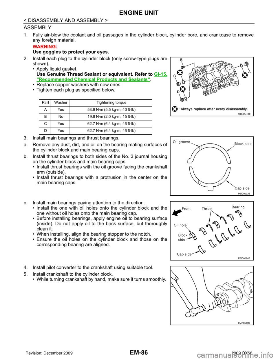
2. Install each plug to the cylinder block (only screw-type plugs are shown).
• Apply liquid gasket. Use Genuine Thread Sealant or equivalent. Refer to GI-15,
"Recommended Chemical Products and Sealants".
• Replace copper washers with new ones.
• Tighten each plug as specified below.
3. Install main bearings and thrust bearings.
a. Remove any dust, dirt, and oil on the bearing mating surfaces of the cylinder block and main bearing caps.
b. Install thrust bearings to both sides of the No. 3 journal housing on the cylinder block and main bearing caps
• Install thrust bearings with the oil groove facing the crankshaft
arm (outside).
• Install thrust bearings with a protrusion in the center on the
main bearing caps.
c. Install main bearings paying attention to the direction. • Install the one with oil holes onto the cylinder block and theone without oil holes onto the main bearing cap.
• Before installing bearings, apply engine oil to bearing surface
(inside). Do not apply oil to the back surface, but thoroughly
clean it.
• When installing, align the bearing stopper to the notch.
• Ensure the oil holes on the cylinder block and those on the
corresponding bearing are aligned.
4. Install pilot converter to the crankshaft using suitable tool.
5. Install crankshaft to the cylinder block. • While turning crankshaft by hand, make sure it turns smoothly.
Part Washer Tightening torque
A Yes 53.9 N·m (5.5 kg-m, 40 ft-lb)
B No 19.6 N·m (2.0 kg-m, 15 ft-lb)
C Yes 62.7 N·m (6.4 kg-m, 46 ft-lb)
D Yes 62.7 N·m (6.4 kg-m, 46 ft-lb)
WBIA0419E
PBIC0093E
PBIC0094E
EMP0569D
Revision: December 20092009 QX56
Page 1956 of 4171

EXL-8
< FUNCTION DIAGNOSIS >
HEADLAMP
A Xenon type headlamp is adapted to the low beam headlamps. Xenon bulbs do not use a filament. Instead,
they produce light when a high voltage current is pa ssed between two tungsten electrodes through a mixture
of Xenon (an inert gas) and certain other metal halides. In addition to added lighting power, electronic control
of the power supply gives the headlamps stable quality and tone color. Following are some of the advantages
of the Xenon type headlamp.
• The light produced by the headlamps is a white color comparable to sunlight that is easy on the eyes.
• Light output is nearly double that of halogen headlamps, affording increased area of illumination.
• The light features a high relative spectral distribution at wavelengths to which the human eye is most sensi- tive. This means that even in the rain, more light is reflected back from the road surface toward the vehicle,
for added visibility.
• Power consumption is approximately 25 percent less than halogen headlamps, reducing battery load.
HIGH BEAM OPERATION/FLASH-TO-PASS OPERATION
With the combination switch (lighting and turn signal switch) in the 2ND position and placed in HIGH position,
the BCM receives input requesting the headlamp high beams to illuminate. The flash to pass feature can be
used any time and also sends a signal to the BCM. This input is communicated to the IPDM E/R via the CAN
communication lines. The CPU of the combination meter c ontrols the ON/OFF status off the HIGH BEAM indi-
cator. The CPU of the IPDM E/R controls the headlamp LH high and RH high relay coils which supplies power
to the high beam headlamps.
The combination meter receives a high beam request signal (ON) via the CAN communication lines and turns
the high beam indicator lamp ON.
Revision: December 20092009 QX56
Page 2098 of 4171
EXL-150
< REMOVAL AND INSTALLATION >
FRONT FOG LAMP
FRONT FOG LAMP
Bulb ReplacementINFOID:0000000003776226
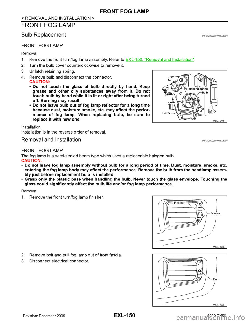
FRONT FOG LAMP
Removal
1. Remove the front turn/fog lamp assembly. Refer to EXL-150, "Removal and Installation".
2. Turn the bulb cover counterclockwise to remove it.
3. Unlatch retaining spring.
4. Remove bulb and disconnect the connector. CAUTION:
• Do not touch the glass of bulb directly by hand. Keep
grease and other oily substances away from it. Do not
touch bulb by hand while it is lit or right after being turned
off. Burning may result.
• Do not leave bulb out of fog la mp reflector for a long time
because dust, moisture smoke, etc. may affect the perfor-
mance of fog lamp. When replacing bulb, be sure to
replace it with new one.
Installation
Installation is in the reverse order of removal.
Removal and InstallationINFOID:0000000003776227
FRONT FOG LAMP
The fog lamp is a semi-sealed beam type which uses a replaceable halogen bulb.
CAUTION:
• Do not leave fog lamp assembly without bulb for a long period of time. Dust, moisture, smoke, etc. entering the fog lamp body may affect the perf ormance. Remove the bulb from the headlamp assem-
bly just before replacement bulb is installed.
• Grasp only the plastic base when handling the bulb. Never touch the glass envelope. Touching the
glass could significantly affect the bulb life and/or fog lamp performance.
Removal
1. Remove the front turn/fog lamp finisher.
2. Remove bolt and pull fog lamp out of front fascia.
3. Disconnect electrical connector.
WKIA1886E
WKIA1887E
WKIA1888E
Revision: December 20092009 QX56