2009 INFINITI QX56 oil type
[x] Cancel search: oil typePage 2176 of 4171
FSU-6
< ON-VEHICLE MAINTENANCE >
ON-VEHICLE SERVICE
ON-VEHICLE MAINTENANCE
ON-VEHICLE SERVICE
Front Suspension PartsINFOID:0000000003772269
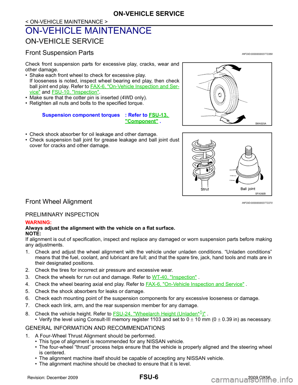
Check front suspension parts for excessive play, cracks, wear and
other damage.
• Shake each front wheel to check for excessive play.If looseness is noted, inspect wheel bearing end play, then check
ball joint end play. Refer to FA X - 6 , "
On-Vehicle Inspection and Ser-
vice" and FSU-10, "Inspection".
• Make sure that the cotter pin is inserted (4WD only).
• Retighten all nuts and bolts to the specified torque.
• Check shock absorber for oil leakage and other damage.
• Check suspension ball joint for grease leakage and ball joint dust cover for cracks and other damage.
Front Wheel AlignmentINFOID:0000000003772270
PRELIMINARY INSPECTION
WARNING:
Always adjust the alignment with the vehicle on a flat surface.
NOTE:
If alignment is out of specificat ion, inspect and replace any damaged or worn suspension parts before making
any adjustments.
1. Check and adjust the wheel alignment with the vehicle under unladen conditions. “Unladen conditions”
means that the fuel, coolant, and lubricant are full; and that the spare tire, jack, hand tools and mats are in
their designated positions.
2. Check the tires for incorrect air pressure and excessive wear.
3. Check the wheels for run out and damage. Refer to WT-40, "
Inspection" .
4. Check the wheel bearing axial end play. Refer to FA X - 6 , "
On-Vehicle Inspection and Service" .
5. Check the shock absorbers for leaks or damage.
6. Check each mounting point of the suspension components for any excessive looseness or damage.
7. Check each link, arm, and the rear suspension member for any damage.
8. Check the vehicle height. Refer to FSU-24, "
Wheelarch Height (Unladen*1)" .
• Verify the level using Consult-III memory register 1103 and set to 0 ± 10 mm (0 ± 0.39 in) as necessary.
GENERAL INFORMATION AND RECOMMENDATIONS
1. A Four-Wheel Thrust Alignment should be performed.
• This type of alignment is recommended for any NISSAN vehicle.
• The four-wheel “thrust” process helps ensure that the vehicle is properly aligned and the steering wheel
is centered.
• The alignment machine itself should be ca pable of accepting any NISSAN vehicle.
• The alignment machine should be checked to ensure that it is level. Suspension component
torques : Refer to FSU-13,
"Component" . SMA525A
SFA392B
Revision: December 20092009 QX56
Page 2193 of 4171
SERVICE DATA AND SPECIFICATIONS (SDS)FSU-23
< SERVICE DATA AND SPECIFICATIONS (SDS)
C
DF
G H
I
J
K L
M A
B
FSU
N
O P
SERVICE DATA AND SPECIFICATIONS (SDS)
SERVICE DATA AND SPECIFICATIONS (SDS)
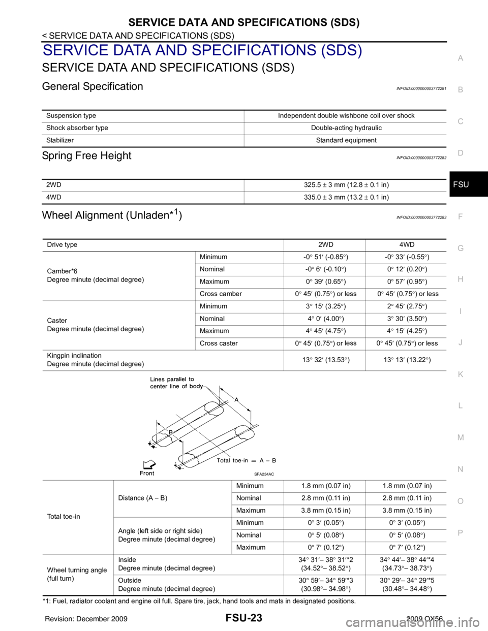
General SpecificationINFOID:0000000003772281
Spring Free HeightINFOID:0000000003772282
Wheel Alignment (Unladen*1)INFOID:0000000003772283
*1: Fuel, radiator coolant and engine oil full. Spare tire, jack, hand tools and mats in designated positions. Suspension type
Independent double wishbone coil over shock
Shock absorber type Double-acting hydraulic
Stabilizer Standard equipment
2WD325.5 ± 3 mm (12.8 ± 0.1 in)
4WD 335.0 ± 3 mm (13.2 ± 0.1 in)
Drive type 2WD 4WD
Camber*6
Degree minute (decimal degree) Minimum
-0° 51 ′ (-0.85 °)- 0° 33 ′ (-0.55 °)
Nominal -0° 6 ′ (-0.10 °)0 ° 12 ′ (0.20 °)
Maximum 0° 39 ′ (0.65 °)0 ° 57 ′ (0.95 °)
Cross camber 0° 45 ′ (0.75 °) or less 0 ° 45′ (0.75 °) or less
Caster
Degree minute (decimal degree) Minimum
3° 15 ′ (3.25 °)2 ° 45 ′ (2.75 °)
Nominal 4° 0 ′ (4.00 °)3 ° 30 ′ (3.50 °)
Maximum 4° 45 ′ (4.75 °)4 ° 15 ′ (4.25 °)
Cross caster 0° 45 ′ (0.75 °) or less 0
° 45 ′ (0
.75°) or less
Kingpin inclination
Degree minute (decimal degree) 13
° 32 ′ (13.53 °)1 3° 13 ′ (13.22 °)
Total toe-in Distance (A
− B) Minimum
1.8 mm (0.07 in) 1.8 mm (0.07 in)
Nominal 2.8 mm (0.11 in) 2.8 mm (0.11 in)
Maximum 3.8 mm (0.15 in) 3.8 mm (0.15 in)
Angle (left side or right side)
Degree minute (decimal degree) Minimum
0° 3 ′ (0.05 °)0 ° 3 ′ (0.05 °)
Nominal 0° 5 ′ (0.08 °)0 ° 5 ′ (0.08 °)
Maximum 0° 7 ′ (0.12 °)0 ° 7 ′ (0.12 °)
Wheel turning angle
(full turn) Inside
Degree minute (decimal degree)
34
° 31 ′– 38 ° 31 ′*2
(34.52 °– 38.52° ) 34
° 44 ′– 38° 44′*4
(34.73 °– 38.73 °)
Ou t
side
Degree minute (decimal degree) 30
° 59 ′– 34 ° 59 ′*3
(30.98 °– 34.98° ) 30
° 29 ′– 34° 29′*5
(30.48 °– 34.48 °)
SFA234AC
Revision: December 20092009 QX56
Page 2194 of 4171
FSU-24
< SERVICE DATA AND SPECIFICATIONS (SDS)
SERVICE DATA AND SPECIFICATIONS (SDS)
*2: Target value 37° 31 ′ (37.52 °)
*3: Target value 33 ° 59 ′ (33.98 °)
*4: Target value 37 ° 44 ′ (37.73 °)
*5: Target value 33 ° 29 ′ (33.48 °)
*6 Some vehicles may not be equipped with straight (non-adjustable) lower link bolts and washers. In order to adjust camber and caster
on these vehicles, first replace the lower link bolts and washers with adjustable (cam) bolts and washers
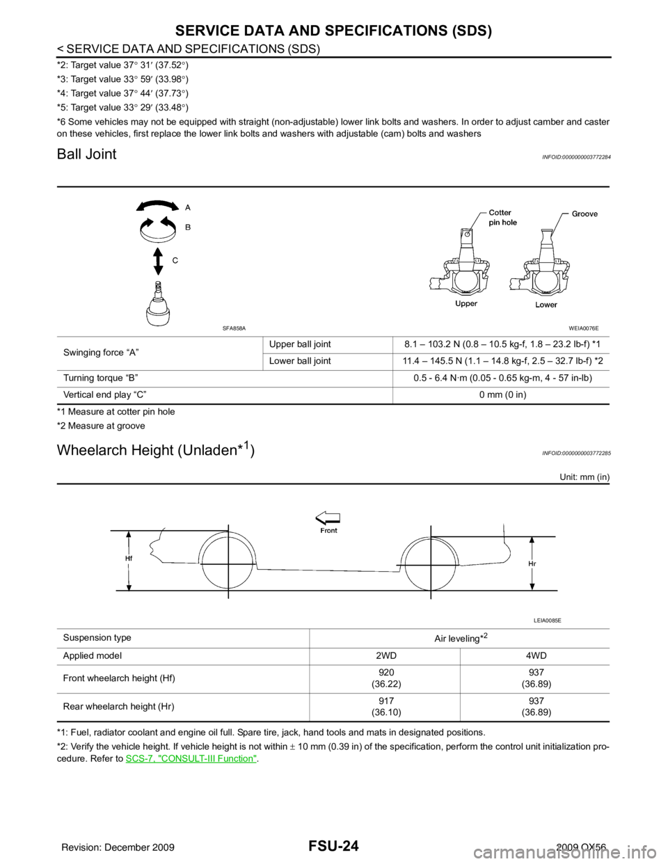
Ball JointINFOID:0000000003772284
*1 Measure at cotter pin hole
*2 Measure at groove
Wheelarch Height (Unladen*1)INFOID:0000000003772285
Unit: mm (in)
*1: Fuel, radiator coolant and engine oil full. Spare tire, jack, hand tools and mats in designated positions.
*2: Verify the vehicle height. If vehicle height is not within ± 10 mm (0.39 in) of the specification, perform the control unit initialization pro-
cedure. Refer to SCS-7, "
CONSULT-III Function".
Swinging force “A”
Upper ball joint
8.1 – 103.2 N (0.8 – 10.5 kg-f, 1.8 – 23.2 lb-f) *1
Lower ball joint 11.4 – 145.5 N (1.1 – 14.8 kg-f, 2.5 – 32.7 lb-f) *2
Turning torque “B” 0.5 - 6.4 N·m (0.05 - 0.65 kg-m, 4 - 57 in-lb)
Vertical end play “C” 0 mm (0 in)
SFA858AWEIA0076E
Suspension type
Air leveling*2
Applied model2WD4WD
Front wheelarch height (Hf) 920
(36.22) 937
(36.89)
Rear wheelarch height (Hr) 917
(36.10) 937
(36.89)
LEIA0085E
Revision: December 20092009 QX56
Page 2273 of 4171
PRECAUTIONSHA-9
< PRECAUTION >
C
DE
F
G H
J
K L
M A
B
HA
N
O P
*: Always check with the Parts Department for the latest parts information.
WARNING:
Make sure all refrigerant is discharged into the recycling equipment and the pressure in the system is
less than atmospheric pressure. Then gradually loo sen the discharge side hose fitting and remove it.
CAUTION:
When replacing or cleaning refrigerant cycle components, observe the following.
When the compressor is removed, st ore it in the same position as it is when mounted on the car.
Failure to do so will cause oil to enter the low pressure chamber.
When connecting tubes, always use a to rque wrench and a back-up wrench.
After disconnecting tubes, immediately plug all op enings to prevent entry of dirt and moisture.
When installing an air conditioner in the vehicle, connect the pipes as the final stage of the opera-
tion. Do not remove the seal caps of pipes and other components until just before required for con-
nection.
Allow components stored in cool areas to warm to working area temperature before removing seal
caps. This prevents condensation from forming inside A/C components.
Thoroughly remove moisture from the refriger ation system before charging the refrigerant.
Always replace used O-rings.
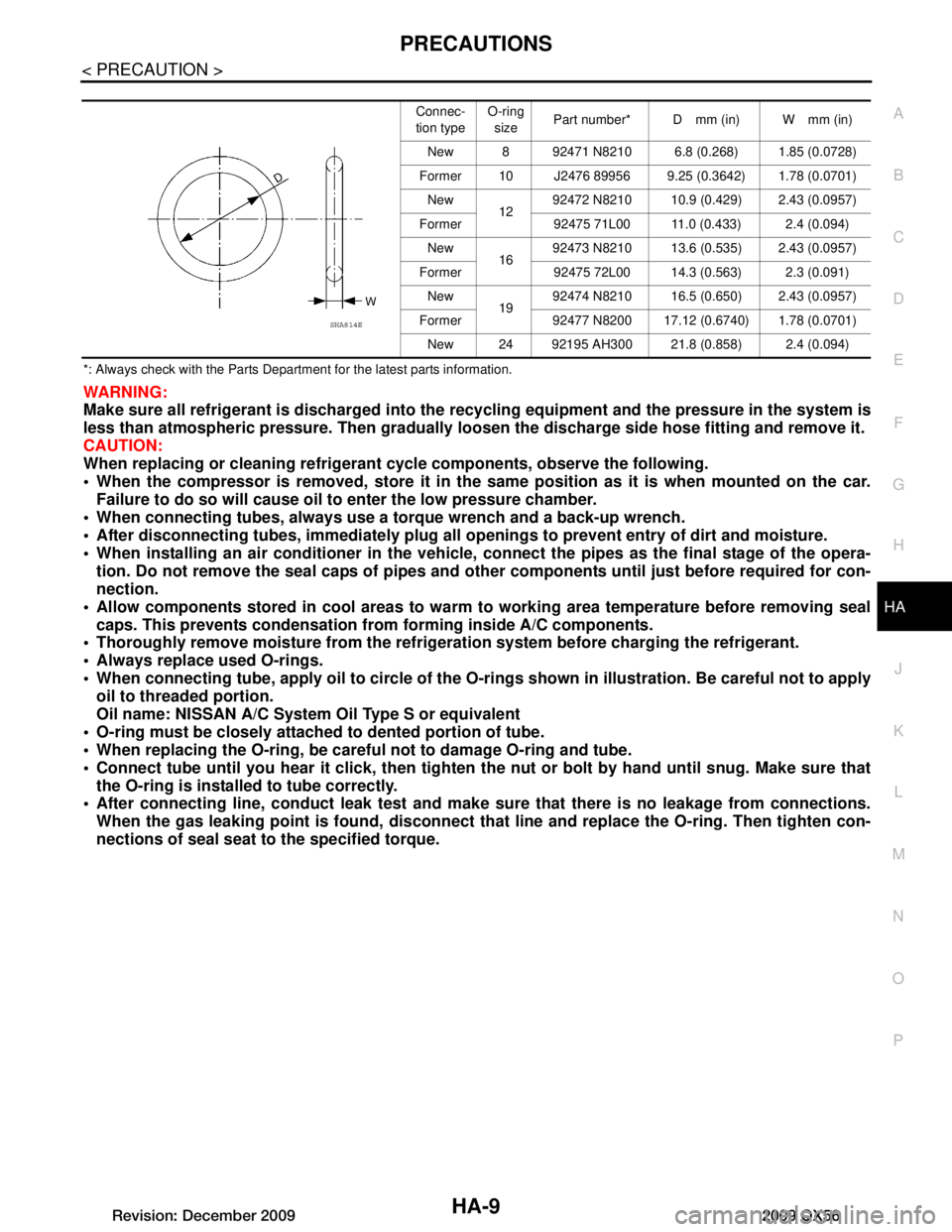
When connecting tube, apply oil to circle of the O-ri ngs shown in illustration. Be careful not to apply
oil to threaded portion.
Oil name: NISSAN A/C System Oil Type S or equivalent
O-ring must be closely attached to dented portion of tube.
When replacing the O-ring, be careful not to damage O-ring and tube.
Connect tube until you hear it cl ick, then tighten the nut or bolt by hand until snug. Make sure that
the O-ring is installed to tube correctly.
After connecting line, conduct leak test and make sure that there is no leakage from connections.
When the gas leaking point is f ound, disconnect that line and replace the O-ring. Then tighten con-
nections of seal seat to the specified torque.
Connec-
tion type O-ring
size Part number* D mm (in) W mm (in)
New 8 92471 N8210 6.8 (0.268) 1.85 (0.0728)
Former 10 J2476 89956 9.25 (0.3642) 1.78 (0.0701) New 1292472 N8210 10.9 (0.429) 2.43 (0.0957)
Former 92475 71L00 11.0 (0.433) 2.4 (0.094) New 1692473 N8210 13.6 (0.535) 2.43 (0.0957)
Former 92475 72L00 14.3 (0.563) 2.3 (0.091) New 1992474 N8210 16.5 (0.650) 2.43 (0.0957)
Former 92477 N8200 17.12 (0.6740) 1.78 (0.0701) New 24 92195 AH300 21.8 (0.858) 2.4 (0.094)
SHA814E
Revision: December 20092009 QX56
Page 2277 of 4171
PREPARATIONHA-13
< PREPARATION >
C
DE
F
G H
J
K L
M A
B
HA
N
O P
PREPARATION
PREPARATION
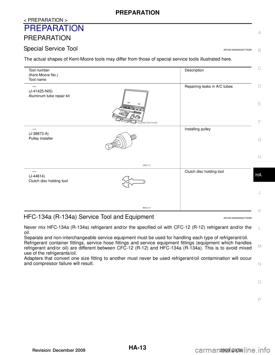
Special Service ToolINFOID:0000000003775295
The actual shapes of Kent-Moore tools may differ fr om those of special service tools illustrated here.
HFC-134a (R-134a) Service Tool and EquipmentINFOID:0000000003775296
Never mix HFC-134a (R-134a) refrigerant and/or the spec ified oil with CFC-12 (R-12) refrigerant and/or the
oil.
Separate and non-interchangeable service equipment must be used for handling each type of refrigerant/oil.
Refrigerant container fittings, service hose fittings and service equipment fittings (equipment which handles
refrigerant and/or oil) are different between CFC-12 (R-12) and HFC-134a (R-134a). This is to avoid mixed
use of the refrigerants/oil.
Adapters that convert one size fitti ng to another must never be used refrigerant/oil contamination will occur
and compressor failure will result.
Tool number
(Kent-Moore No.)
Tool name Description
—
(J-41425-NIS)
Aluminum tube repair kit Repairing leaks in A/C tubes
—
(J-38873-A)
Pulley installer Installing pulley
—
(J-44614)
Clutch disc holding tool Clutch disc holding tool
ALIIA0390ZZ
LHA171
WHA230
Revision: December 20092009 QX56
Page 2278 of 4171
HA-14
< PREPARATION >
PREPARATION
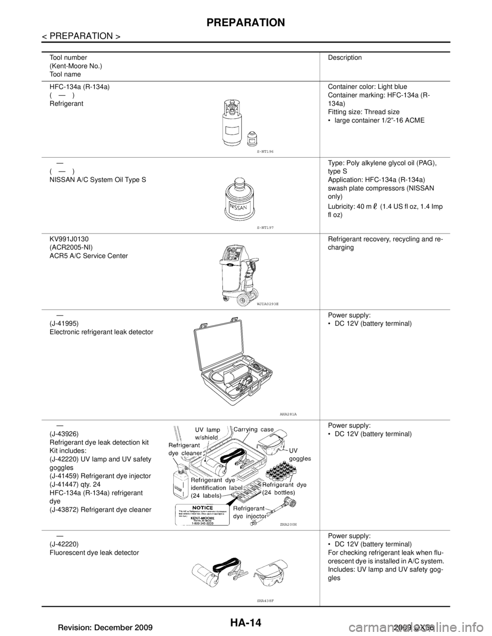
Tool number
(Kent-Moore No.)
Tool nameDescription
HFC-134a (R-134a)
(—)
Refrigerant Container color: Light blue
Container marking: HFC-134a (R-
134a)
Fitting size: Thread size
large container 1/2”-16 ACME
—
(—)
NISSAN A/C System Oil Type S Type: Poly alkylene glycol oil (PAG),
type S
Application: HFC-134a (R-134a)
swash plate compressors (NISSAN
only)
Lubricity: 40 m (1.4 US fl oz, 1.4 Imp
fl oz)
KV991J0130
(ACR2005-NI)
ACR5 A/C Service Center Refrigerant recovery, recycling and re-
charging
—
(J-41995)
Electronic refrigerant leak detector Power supply:
DC 12V (batte
ry terminal)
—
(J-43926)
Refrigerant dye leak detection kit
Kit includes:
(J-42220) UV lamp and UV safety
goggles
(J-41459) Refrigerant dye injector
(J-41447) qty. 24
HFC-134a (R-134a) refrigerant
dye
(J-43872) Refrigerant dye cleaner Power supply:
DC 12V (batte
ry terminal)
—
(J-42220)
Fluorescent dye leak detector Power supply:
DC 12V (batte
ry terminal)
For checking refrigerant leak when flu-
orescent dye is installed in A/C system.
Includes: UV lamp and UV safety gog-
gles
S-NT196
S-NT197
WJIA0293E
AHA281A
ZHA200H
SHA438F
Revision: December 20092009 QX56
Page 2286 of 4171
HA-22
< ON-VEHICLE MAINTENANCE >
OIL
OIL
Maintenance of Oil Quantity in CompressorINFOID:0000000003775302
The oil in the compressor circulates through the system with the refrigerant. Add oil to compressor when
replacing any component or after a large refrigerant leakage has occurred. It is important to maintain the spec-
ified amount.
If oil quantity is not maintained properly, the following malfunctions may result:
Lack of oil: May lead to a seized compressor
Excessive oil: Inadequate cooling (thermal exchange interference)
OIL
Name: NISSAN A/C System Oil Type S or equivalent
CHECKING AND ADJUSTING
CAUTION:
If excessive oil leakage is noted, do no t perform the oil return operation.
Start the engine and set the following conditions:
Test Condition
Engine speed: Idling to 1,200 rpm
A/C switch: On
Blower fan speed: MAX position
Temp. control: Optional [Set so that intake air temperature is 25 ° to 30 ° C (77 ° to 86 °F)]
Intake position: Recirculation ( )
Perform oil return operation for about ten minutes
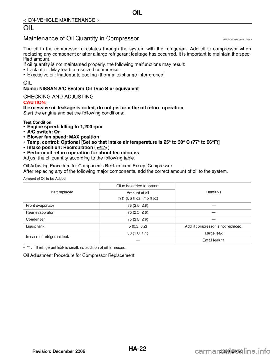
Adjust the oil quantity according to the following table.
Oil Adjusting Procedure for Components Replacement Except Compressor
After replacing any of the following major component s, add the correct amount of oil to the system.
Amount of Oil to be Added
*1: If refrigerant leak is small, no addition of oil is needed.
Oil Adjustment Procedure for Compressor Replacement
Part replacedOil to be added to system
Remarks
Amount of oil
m (US fl oz, Imp fl oz)
Front evaporator 75 (2.5, 2.6) —
Rear evaporator 75 (2.5, 2.6) —
Condenser 75 (2.5, 2.6) —
Liquid tank 5 (0.2, 0.2) Add if compressor is not replaced.
In case of refrigerant leak 30 (1.0, 1.1) Large leak
— Small leak *1
Revision: December 20092009 QX56
Page 2313 of 4171
SERVICE DATA AND SPECIFICATIONS (SDS)
HA-49
< SERVICE DATA AND SPECIFICATIONS (SDS)
C
D E
F
G H
J
K L
M A
B
HA
N
O P
SERVICE DATA AND SPECIFICATIONS (SDS)
SERVICE DATA AND SPECIFICATIONS (SDS)
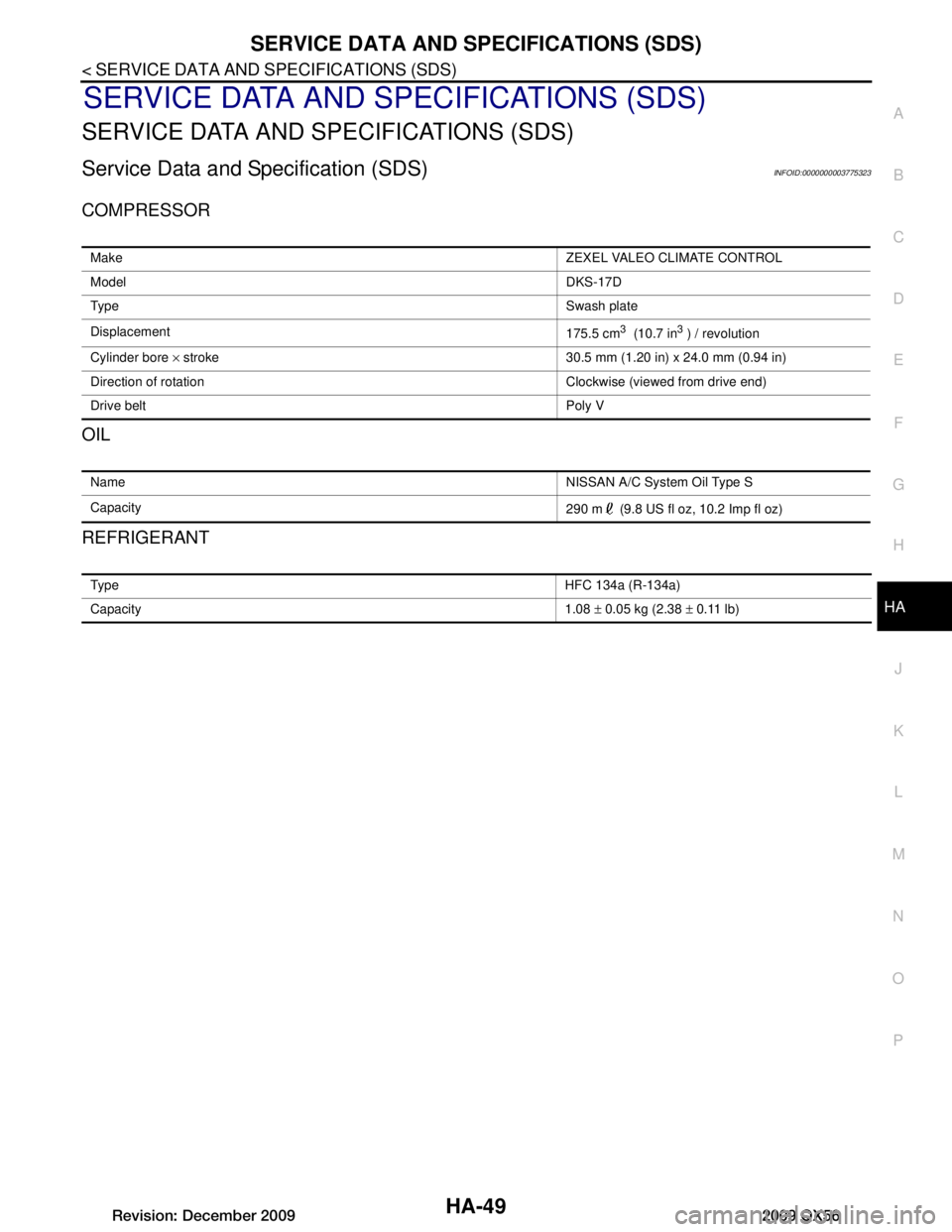
Service Data and Specification (SDS)INFOID:0000000003775323
COMPRESSOR
OIL
REFRIGERANT
Make ZEXEL VALEO CLIMATE CONTROL
Model DKS-17D
Typ e Swash plate
Displacement 175.5 cm
3 (10.7 in3 ) / revolution
Cylinder bore × stroke 30.5 mm (1.20 in) x 24.0 mm (0.94 in)
Direction of rotation Clockwise (viewed from drive end)
Drive belt Poly V
Name NISSAN A/C System Oil Type S
Capacity 290 m (9.8 US fl oz, 10.2 Imp fl oz)
Typ eHFC 134a (R-134a)
Capacity 1.08 ± 0.05 kg (2.38 ± 0.11 lb)
Revision: December 20092009 QX56