2009 INFINITI QX56 ignition
[x] Cancel search: ignitionPage 3432 of 4171
SN-10
< FUNCTION DIAGNOSIS >
FRONT AND REAR SONAR SYSTEM
FRONT AND REAR SONAR SYSTEM
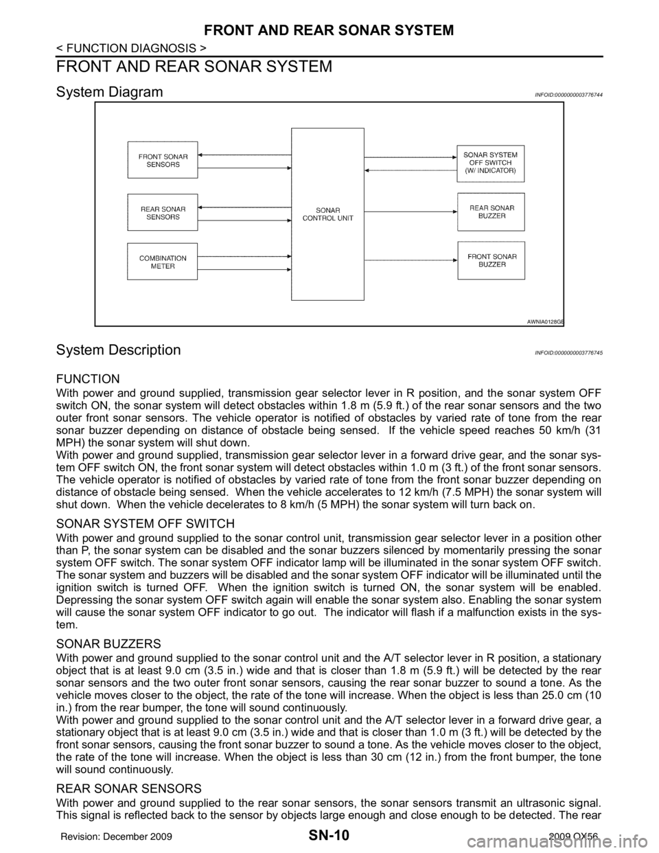
System DiagramINFOID:0000000003776744
System DescriptionINFOID:0000000003776745
FUNCTION
With power and ground supplied, transmission gear selector lever in R position, and the sonar system OFF
switch ON, the sonar system will detect obstacles within 1.8 m (5.9 ft.) of the rear sonar sensors and the two
outer front sonar sensors. The vehicle operator is notif ied of obstacles by varied rate of tone from the rear
sonar buzzer depending on distance of obstacle being sens ed. If the vehicle speed reaches 50 km/h (31
MPH) the sonar syst em will shut down.
With power and ground supplied, transmission gear selector lever in a forward drive gear, and the sonar sys-
tem OFF switch ON, the front sonar system will detect obstacles within 1.0 m (3 ft.) of the front sonar sensors.
The vehicle operator is notified of obstacles by varied rate of tone from the front sonar buzzer depending on
distance of obstacle being sensed. When the vehicle accelerates to 12 km/h (7.5 MPH) the sonar system will
shut down. When the vehicle decelerates to 8 km/h (5 MPH) the sonar system will turn back on.
SONAR SYSTEM OFF SWITCH
With power and ground supplied to the sonar control unit, transmission gear selector lever in a position other
than P, the sonar system can be di sabled and the sonar buzzers silenced by momentarily pressing the sonar
system OFF switch. The sonar system OFF indicator lamp will be illuminated in the sonar system OFF switch.
The sonar system and buzzers will be di sabled and the sonar system OFF indicator will be illuminated until the
ignition switch is turned OFF. When the ignition switch is turned ON, the sonar system will be enabled.
Depressing the sonar system OFF switch again will enabl e the sonar system also. Enabling the sonar system
will cause the sonar system OFF indicator to go out. The indicator will flash if a malfunction exists in the sys-
tem.
SONAR BUZZERS
With power and ground supplied to the sonar control unit and the A/T selector lever in R position, a stationary
object that is at least 9.0 cm (3.5 in.) wide and that is closer than 1.8 m (5.9 ft.) will be detected by the rear
sonar sensors and the two outer front sonar sensors, causing the rear sonar buzzer to sound a tone. As the
vehicle moves closer to the object, the rate of the tone will increase. When the object is less than 25.0 cm (10
in.) from the rear bumper, the tone will sound continuously.
With power and ground supplied to the sonar control unit and the A/T selector lever in a forward drive gear, a
stationary object that is at least 9.0 cm (3.5 in.) wide and that is closer than 1.0 m (3 ft.) will be detected by the
front sonar sensors, causing the front sonar buzzer to sound a tone. As the vehicle moves closer to the object,
the rate of the tone will increase. When the object is less than 30 cm (12 in.) from the front bumper, the tone
will sound continuously.
REAR SONAR SENSORS
With power and ground supplied to the rear sonar sens ors, the sonar sensors transmit an ultrasonic signal.
This signal is reflected back to the sensor by objects large enough and close enough to be detected. The rear
AWNIA0128GB
Revision: December 20092009 QX56
Page 3435 of 4171
SN
POWER SUPPLY AND GROUND CIRCUITSN-13
< COMPONENT DIAGNOSIS >
C
DE
F
G H
I
J
K L
M B A
O P
COMPONENT DIAGNOSIS
POWER SUPPLY AND GROUND CIRCUIT
Diagnosis Procedure (With Rear Sonar System)INFOID:0000000004173800
INSPECTION FOR POWER SUPPLY AND GROUND CIRCUIT
1.CHECK FUSES
Check for blown rear sonar system fuses.
Are any fuses blown?
YES >> If fuse is blown, be sure to eliminate cause of malfunction before installing new fuse. Refer to GI-
41, "Circuit Inspection".
NO >> GO TO 2.
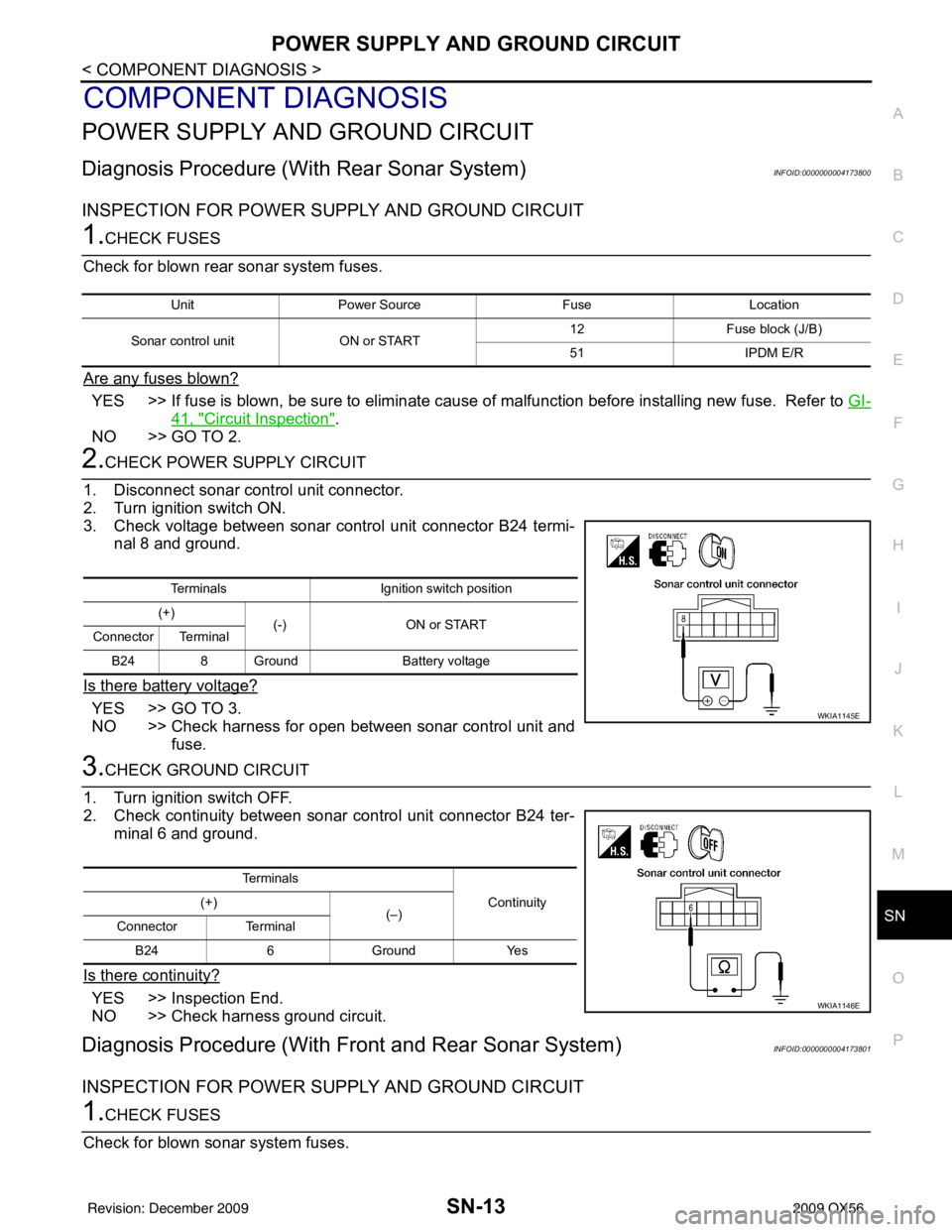
2.CHECK POWER SUPPLY CIRCUIT
1. Disconnect sonar control unit connector.
2. Turn ignition switch ON.
3. Check voltage between sonar control unit connector B24 termi- nal 8 and ground.
Is there battery voltage?
YES >> GO TO 3.
NO >> Check harness for open between sonar control unit and fuse.
3.CHECK GROUND CIRCUIT
1. Turn ignition switch OFF.
2. Check continuity between sonar control unit connector B24 ter- minal 6 and ground.
Is there continuity?
YES >> Inspection End.
NO >> Check harness ground circuit.
Diagnosis Procedure (With Front and Rear Sonar System)INFOID:0000000004173801
INSPECTION FOR POWER SUPPLY AND GROUND CIRCUIT
1.CHECK FUSES
Check for blown sonar system fuses.
Unit Power Source FuseLocation
Sonar control unit ON or START 12
Fuse block (J/B)
51 IPDM E/R
Terminals Ignition switch position
(+) (-) ON or START
Connector Terminal
B24 8 Ground Battery voltage
WKIA1145E
Te r m i n a l s
Continuity
(+)
(–)
Connector Terminal
B24 6 Ground Yes
WKIA1146E
Revision: December 20092009 QX56
Page 3436 of 4171
SN-14
< COMPONENT DIAGNOSIS >
POWER SUPPLY AND GROUND CIRCUIT
Are any fuses blown?
YES >> If fuse is blown, be sure to eliminate cause of malfunction before installing new fuse. Refer to GI-
41, "Circuit Inspection".
NO >> GO TO 2.
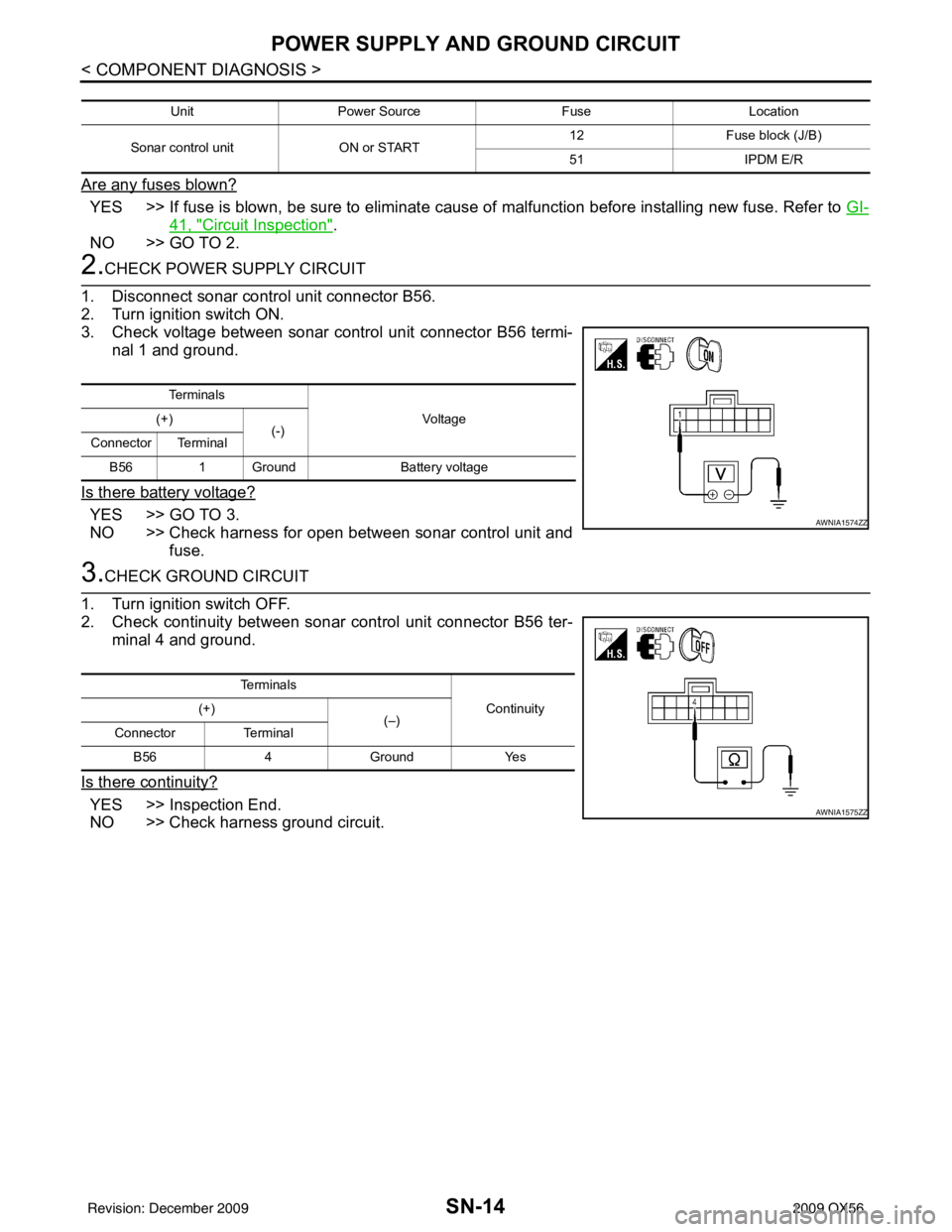
2.CHECK POWER SUPPLY CIRCUIT
1. Disconnect sonar control unit connector B56.
2. Turn ignition switch ON.
3. Check voltage between sonar control unit connector B56 termi- nal 1 and ground.
Is there battery voltage?
YES >> GO TO 3.
NO >> Check harness for open between sonar control unit and fuse.
3.CHECK GROUND CIRCUIT
1. Turn ignition switch OFF.
2. Check continuity between sonar control unit connector B56 ter-
minal 4 and ground.
Is there continuity?
YES >> Inspection End.
NO >> Check harness ground circuit.
Unit Power Source FuseLocation
Sonar control unit ON or START 12
Fuse block (J/B)
51 IPDM E/R
Te r m i n a l s
Vo l ta g e
(+)
(-)
Connector Terminal
B56 1 Ground Battery voltage
AWNIA1574ZZ
Te r m i n a l s
Continuity
(+)
(–)
Connector Terminal
B56 4Ground Yes
AWNIA1575ZZ
Revision: December 20092009 QX56
Page 3437 of 4171
SN
SONAR SENSOR CIRCUIT INSPECTIONSN-15
< COMPONENT DIAGNOSIS >
C
DE
F
G H
I
J
K L
M B A
O P
SONAR SENSOR CIRCUIT INSPECTION
DescriptionINFOID:0000000004173802
With power and ground supplied to the sonar sensors, the sonar sensors transmit an ultrasonic signal. This
signal is reflected back to the sensor by objec ts large enough and close enough to be detected. The sonar
sensors measure the time from the transmitted signal to the time the signal is reflected back and send this
information to the sonar control unit.
Diagnosis Procedure (With Rear Sonar System)INFOID:0000000004173803
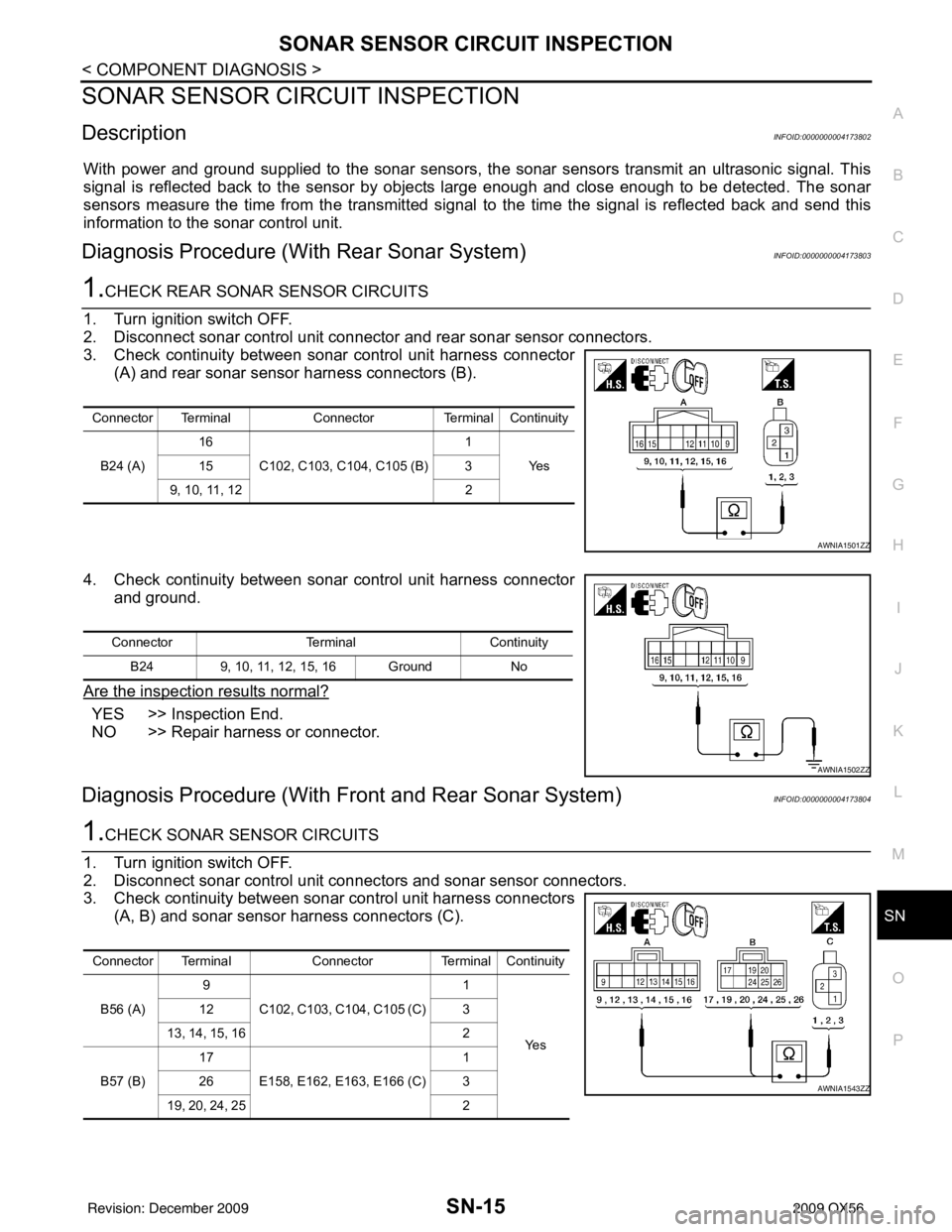
1.CHECK REAR SONAR SENSOR CIRCUITS
1. Turn ignition switch OFF.
2. Disconnect sonar control unit connector and rear sonar sensor connectors.
3. Check continuity between sonar control unit harness connector (A) and rear sonar sensor harness connectors (B).
4. Check continuity between sonar control unit harness connector and ground.
Are the inspection results normal?
YES >> Inspection End.
NO >> Repair harness or connector.
Diagnosis Procedure (With Front and Rear Sonar System)INFOID:0000000004173804
1.CHECK SONAR SENSOR CIRCUITS
1. Turn ignition switch OFF.
2. Disconnect sonar control unit connec tors and sonar sensor connectors.
3. Check continuity between sonar control unit harness connectors (A, B) and sonar sensor harness connectors (C).
Connector Terminal ConnectorTerminal Continuity
B24 (A) 16
C102, C103, C104, C105 (B) 1
Ye s
15 3
9, 10, 11, 12 2
AWNIA1501ZZ
ConnectorTerminalContinuity
B24 9, 10, 11, 12, 15, 16 Ground No
AWNIA1502ZZ
Connector TerminalConnectorTerminal Continuity
B56 (A) 9
C102, C103, C104, C105 (C) 1
Ye s
12
3
13, 14, 15, 16 2
B57 (B) 17
E158, E162, E1 63, E166 (C) 1
26 3
19, 20, 24, 25 2
AWNIA1543ZZ
Revision: December 20092009 QX56
Page 3439 of 4171
SN
SONAR BUZZER CIRCUIT INSPECTIONSN-17
< COMPONENT DIAGNOSIS >
C
DE
F
G H
I
J
K L
M B A
O P
SONAR BUZZER CIRCUIT INSPECTION
DescriptionINFOID:0000000004173805
When the A/T selector lever is not it park or neutral, a stationary object will be detected by the sonar sensors
causing the front or rear sonar buzzer to sound a tone. As the vehicle moves closer to the object, the rate of
the tone will increase. When the object is very cl ose to the vehicle, the tone will sound continuously.
Diagnosis Procedure (With Rear Sonar System)INFOID:0000000004173806
1.CHECK SONAR BUZZER
Refer to SN-18, "
Component Inspection".
Is the inspection result normal?
YES >> GO TO 2.
NO >> Replace sonar buzzer. Refer to SN-51, "
Removal and Installation".
2.CHECK SONAR BUZZER CIRCUITS
1. Turn ignition switch OFF.
2. Disconnect sonar control unit connector and sonar buzzer connector.
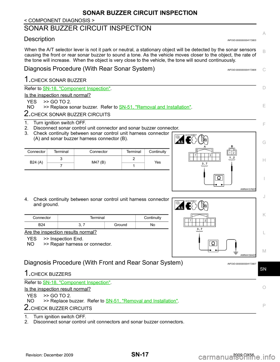
3. Check continuity between sonar control unit harness connector (A) and sonar buzzer harness connector (B).
4. Check continuity between sonar control unit harness connector and ground.
Are the inspection results normal?
YES >> Inspection End.
NO >> Repair harness or connector.
Diagnosis Procedure (With Front and Rear Sonar System)INFOID:0000000004173807
1.CHECK BUZZERS
Refer to SN-18, "
Component Inspection".
Is the inspection result normal?
YES >> GO TO 2.
NO >> Replace buzzer. Refer to SN-51, "
Removal and Installation".
2.CHECK BUZZER CIRCUITS
1. Turn ignition switch OFF.
2. Disconnect sonar control unit connec tors and sonar buzzer connectors.
Connector TerminalConnector Terminal Continuity
B24 (A) 3
M47 (B) 2
Ye s
71
AWNIA1576ZZ
Connector TerminalContinuity
B24 3, 7Ground No
AWNIA1504ZZ
Revision: December 20092009 QX56
Page 3441 of 4171

SN
SONAR SYSTEM OFF SWITCH CIRCUIT INSPECTIONSN-19
< COMPONENT DIAGNOSIS >
C
DE
F
G H
I
J
K L
M B A
O P
SONAR SYSTEM OFF SWITCH CIRCUIT INSPECTION
DescriptionINFOID:0000000004173809
The sonar system can be disabled by momentarily pressing the sonar system OFF switch. The sonar system
OFF indicator lamp will be illuminated when the sonar s ystem is OFF. Enabling the sonar system will cause
the sonar system OFF indicator to go out. The indica tor will flash if a malfunction exists in the system.
Diagnosis Procedure (With Rear Sonar System)INFOID:0000000004173810
1.CHECK REAR SONAR SYSTEM OFF SWITCH
Refer to SN-20, "
Component Inspection".
Is the inspection result normal?
YES >> GO TO 2.
NO >> Replace rear sonar system OFF switch. Refer to IP-15, "
Removal and Installation".
2.CHECK REAR SONAR SYSTEM OFF SWITCH CIRCUITS
1. Turn ignition switch OFF.
2. Disconnect sonar control unit connector and rear sonar system OFF switch connector.
3. Check continuity between sonar control unit harness connector (A) and rear sonar system OFF switch harness connector (B).
4. Check continuity between rear sonar system OFF switch har- ness connector and ground.
Are the inspection results normal?
YES >> Inspection End.
NO >> Repair harness or connector.
Diagnosis Procedure (With Front and Rear Sonar System)INFOID:0000000004173811
1.CHECK SONAR SYSTEM OFF SWITCH
Refer to SN-20, "
Component Inspection".
Is the inspection result normal?
YES >> GO TO 2.
NO >> Replace sonar system OFF switch. Refer to IP-15, "
Removal and Installation".
2.CHECK SONAR SYSTEM OFF SWITCH CIRCUITS
1. Turn ignition switch OFF.
2. Disconnect sonar control unit connector and sonar system OFF switch connector.
Connector TerminalConnector Terminal Continuity
B24 (A) 4
M117 (B) 5
Ye s
13 1
AWNIA1577ZZ
ConnectorTerminalContinuity
M117 1, 5
Ground No
2, 6 Yes
AWNIA1578ZZ
Revision: December 20092009 QX56
Page 3443 of 4171
SN
SONAR CONTROL UNIT FOR REAR SONAR SYSTEMSN-21
< ECU DIAGNOSIS >
C
DE
F
G H
I
J
K L
M B A
O P
ECU DIAGNOSIS
SONAR CONTROL UNIT FO R REAR SONAR SYSTEM
Reference ValueINFOID:0000000003776753
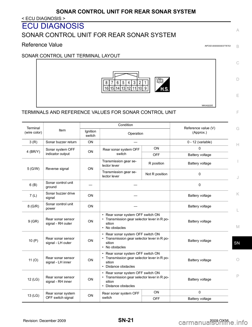
SONAR CONTROL UNIT TERMINAL LAYOUT
TERMINALS AND REFERENCE VA LUES FOR SONAR CONTROL UNIT
WKIA5222E
Te r m i n a l
(wire color) Item Condition
Reference value (V)
(Approx.)
Ignition
switch Operation
3 (R) Sonar buzzer return ON —0 - 12 (variable)
4 (BR/Y) Sonar system OFF
indicator output ON
Rear sonar system OFF
switch ON
0
OFF Battery voltage
5 (G/W) Reverse signal ONTransmission gear se-
lector lever
R position
Battery voltage
Transmission gear se-
lector lever Not R position
0
6 (B) Sonar control unit
ground ——
0
7 (L) Sonar buzzer drive
signal
ON
— Battery voltage
8 (G/R) Sonar control unit
power ON
— Battery voltage
9 (GR) Rear sonar sensor
signal - RH outer
ON• Rear sonar system OFF switch ON
• Transmission gear selector lever in R po-
sition
• No obstacles Battery voltage
10 (P) Rear sonar sensor
signal - LH outer
ON• Rear sonar system OFF switch ON
• Transmission gear selector lever in R po-
sition
• No obstacles Battery voltage
11 ( O ) Rear sonar sensor
signal - LH inner
ON• Rear sonar system OFF switch ON
• Transmission gear selector lever in R po-
sition
• Distance obstacles Battery voltage
12 (LG) Rear sonar sensor
signal - RH inner
ON• Rear sonar system OFF switch ON
• Transmission gear selector lever in R po-
sition
• Distance obstacles Battery voltage
13 (LG) Rear sonar system
OFF switch signal
ONRear sonar system OFF
switch ON
0
OFF Battery voltage
Revision: December 20092009 QX56
Page 3444 of 4171

SN-22
< ECU DIAGNOSIS >
SONAR CONTROL UNIT FOR REAR SONAR SYSTEM
15 (Y)Rear sonar sensor
ground
ON
— 0
16 (LG/B) Rear sonar sensor
power ON Ignition switch ON
Battery voltage
Te r m i n a l
(wire color) Item Condition
Reference value (V)
(Approx.)
Ignition
switch Operation
Revision: December 20092009 QX56