2009 INFINITI QX56 4WD
[x] Cancel search: 4WDPage 2217 of 4171
IDENTIFICATION INFORMATIONGI-23
< FEATURES OF NEW MODEL >
C
DE
F
G H
I
J
K L
M B
GI
N
O P
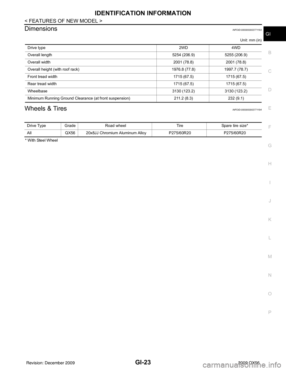
DimensionsINFOID:0000000003771193
Unit: mm (in)
Wheels & TiresINFOID:0000000003771194
* With Steel Wheel Drive type
2WD4WD
Overall length 5254 (206.9)5255 (206.9)
Overall width 2001 (78.8)2001 (78.8)
Overall height (with roof rack) 1976.8 (77.8)1997.7 (78.7)
Front tread width 1715 (67.5)1715 (67.5)
Rear tread width 1715 (67.5)1715 (67.5)
Wheelbase 3130 (123.2)3130 (123.2)
Minimum Running Ground Clearance (at front suspension) 211.2 (8.3)232 (9.1)
Drive Type Grade Road wheelTireSpare tire size*
All QX56 20x8JJ Chromium Aluminum Alloy P275/60R20P275/60R20
Revision: December 20092009 QX56
Page 2226 of 4171
GI-32
< PRECAUTION >
TOW TRUCK TOWING
TOW TRUCK TOWING
Tow Truck TowingINFOID:0000000005867507
WARNING:
• Never get under the vehicle while it is supported only by the jack. Always use safety stands to sup-
port the frame when you have to get under the vehicle.
• Place wheel chocks at both front an d back of the wheels on the ground.
CAUTION:
• All applicable State or Provincial (in Canada) laws and local laws regarding the towing operation
must be obeyed.
• It is necessary to use proper towing equipment to avoid possible damage during towing operation.
Towing is in accordance with Towing Procedure Manual at dealer.
• Always attach safety chains before towing.
• When towing, make sure that the transmission, steering system and powertrain are in good order. If any unit is damaged, dollies must be used.
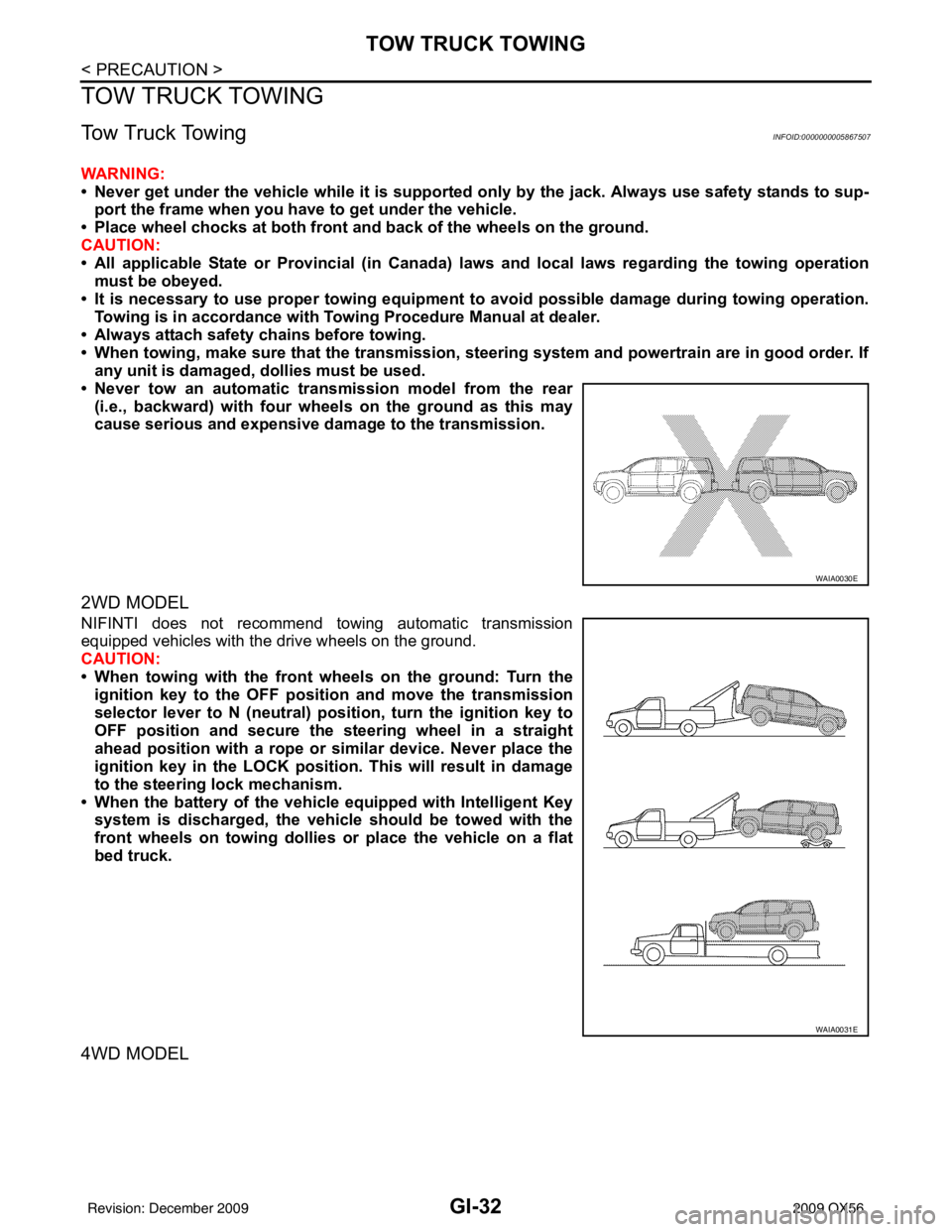
• Never tow an automatic transmission model from the rear (i.e., backward) with four wh eels on the ground as this may
cause serious and expensive dama ge to the transmission.
2WD MODEL
NIFINTI does not recommend towing automatic transmission
equipped vehicles with the drive wheels on the ground.
CAUTION:
• When towing with the front wheels on the ground: Turn the
ignition key to the OFF posit ion and move the transmission
selector lever to N (neutral) pos ition, turn the ignition key to
OFF position and secure the steering wheel in a straight
ahead position with a rope or similar device. Never place the
ignition key in the LOCK position. This will result in damage
to the steering lock mechanism.
• When the battery of the vehicle equipped with Intelligent Key system is discharged, the vehicle should be towed with the
front wheels on towing dollies or place the vehicle on a flat
bed truck.
4WD MODEL
WAIA0030E
WAIA0031E
Revision: December 20092009 QX56
Page 2227 of 4171
TOW TRUCK TOWINGGI-33
< PRECAUTION >
C
DE
F
G H
I
J
K L
M B
GI
N
O P
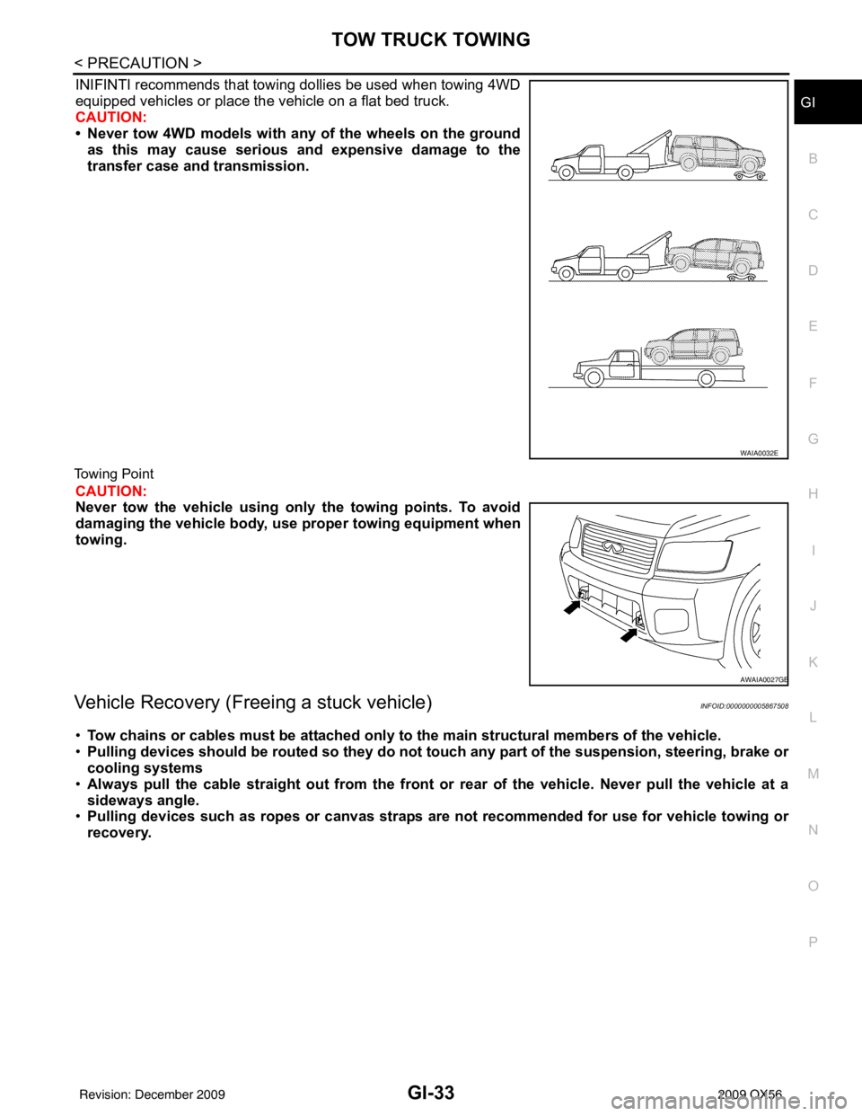
INIFINTI recommends that towing dollies be used when towing 4WD
equipped vehicles or place the vehicle on a flat bed truck.
CAUTION:
• Never tow 4WD models with any of the wheels on the ground as this may cause serious and expensive damage to the
transfer case and transmission.
Towing Point
CAUTION:
Never tow the vehicle using only the towing points. To avoid
damaging the vehicle body, use proper towing equipment when
towing.
Vehicle Recovery (Freeing a stuck vehicle)INFOID:0000000005867508
•Tow chains or cables must be attached only to the main structural members of the vehicle.
• Pulling devices should be routed so they do not touch any part of the suspension, steering, brake or
cooling systems
• Always pull the cable straight out from the front or rear of the vehicle. Never pull the vehicle at a
sideways angle.
• Pulling devices such as ropes or canvas straps are not recommended for use for vehicle towing or
recovery.
WAIA0032E
AWAIA0027GB
Revision: December 20092009 QX56
Page 2240 of 4171
GI-46
< BASIC INSPECTION >
CONSULT-III CHECKING SYSTEM
CONSULT-III CHECKING SYSTEM
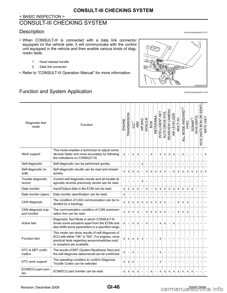
DescriptionINFOID:0000000003771217
• When CONSULT-III is connected with a data link connectorequipped on the vehicle side, it will communicate with the control
unit equipped in the vehicle and then enable various kinds of diag-
nostic tests.
• Refer to “CONSULT-III Operation Manual” for more information.
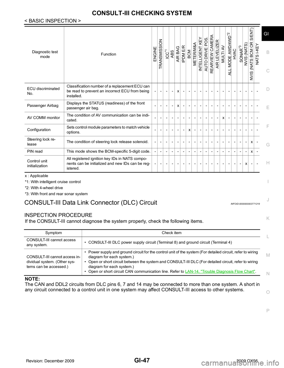
Function and System ApplicationINFOID:0000000003771218
1 : Hood release handle
2 : Data link connector
ALBIA0047ZZ
Diagnostic test mode Function
ENGINE
TRANSMISSION
ICC
*1
ABS
AIR BAG
IPDM E/R BCM
METER/M&A
INTELLIGENT KEY
AUTO DRIVE POS.
REARVIEW CAMERA AIR LEVELIZER MULTI AV
ALL MODE AWD/4WD
*2
HVAC
SONAR
*3
NVIS (NATS)
NVIS (NATS BCM OR S/ENT) NATS I-KEY
Work support This mode enables a technician to adjust some
devices faster and more accurately by following
the indications on CONSULT-III. x-xx--x-xxxx-x----x
Self-diagnostic Self-diagnostic can be performed quickly. ----x--------------
Self-diagnostic re-
sults Self-diagnostic results can be read and erased
quickly.
xxx x- xxxxx- xxx xxxxx
Trouble diagnostic
record Current self-diagnostic results and all trouble di-
agnostic records previously stored can be read.
--- - x--- - ----------
Data monitor Input/Output data in the ECM can be read. xxx x- x- xxxxxxx xx- - -
Data monitor (spec) Data monitor specification can be read. x------------------
CAN diagnosis The condition of CAN communication can be in-
dicated by a topology.
xxx xxxxxxx- - xx x- - - -
CAN diagnosis sup-
port monitor The communication condition of CAN communi-
cation line can be read.
xxx x- xxxxx- - xx x- - - -
Active test Diagnostic Test Mode
in which CONSULT-III
drives some actuators apart from the ECMs and
also shifts some parameters in a specified range. x-xx-x--xx-x-------
Function test This mode can show results of self-diagnosis of
ECU with either “OK” or “NG”. For engines, more
practical tests regarding sensors/switches and/
or actuators are available. xxxxx---x----------
DTC & SRT confir-
mation The results of SRT (System Readiness Test) and
the self-diagnosis status/result can be confirmed.
x-x-----x----------
DTC work support The operating condition to confirm Diagnosis
Trouble Codes can be selected. xxx-----x----------
ECM/ECU part num-
ber ECM/ECU part number can be read.
xxx x- - x- xxxxxx xx- - -
Revision: December 20092009 QX56
Page 2241 of 4171
CONSULT-III CHECKING SYSTEMGI-47
< BASIC INSPECTION >
C
DE
F
G H
I
J
K L
M B
GI
N
O P
x : Applicable
*1: With intelligent cruise control
*2: With 4-wheel drive
*3: With front and rear sonar system
CONSULT-III Data Link Connector (DLC) CircuitINFOID:0000000003771219
INSPECTION PROCEDURE
If the CONSULT-III cannot diagnose the sys tem properly, check the following items.
NOTE:
The CAN and DDL2 circuits from DLC pins 6, 7 and 14 may be connected to more than one system. A short in
any circuit connected to a control unit in one system may affect CONSULT-III access to other systems.
ECU discriminated
No.Classification number of a replacement ECU can
be read to prevent an incorrect ECU from being
installed.
----x--------------
Passenger Airbag Displays the STATUS (readiness) of the front
passenger air bag.
----x--------------
AV COMM monitor The condition of AV communication can be indi-
cated. ------------x------
Configuration Sets control module para
meters to match vehicle
options. ------x------------
Steering lock re-
lease The condition of steering lock release solenoid. -----------------x-
PIN read This mode shows the BCM-specific 5-digit code.-----------------x-
Control unit
initialization All registered ignition key IDs in NATS compo-
nents can be initialized and new IDs can be reg-
istered.
----------------x--
Diagnostic test
mode Function
ENGINE
TRANSMISSION
ICC
*1
ABS
AIR BAG
IPDM E/R BCM
METER/M&A
INTELLIGENT KEY
AUTO DRIVE POS.
REARVIEW CAMERA AIR LEVELIZER
MULTI AV
ALL MODE AWD/4WD
*2
HVAC
SONAR
*3
NVIS (NATS)
NVIS (NATS BCM OR S/ENT) NATS I-KEY
Symptom Check item
CONSULT-III cannot access
any system. • CONSULT-III DLC power supply circuit (Terminal 8) and ground circuit (Terminal 4)
CONSULT-III cannot access in-
dividual system. (Other sys-
tems can be accessed.) • Power supply and ground circuit for the control unit of the system (For detailed circuit, refer to wiring
diagram for each system.)
• Open or short circuit between the system and CONSULT-III DLC (For detailed circuit, refer to wiring diagram for each system.)
• Open or short circuit CAN communication line. Refer to LAN-14, "
Trouble Diagnosis Flow Chart".
Revision: December 20092009 QX56
Page 2557 of 4171
INSTRUMENT PANEL ASSEMBLYIP-13
< ON-VEHICLE REPAIR >
C
DE
F
G H
I
K L
M A
B
IP
N
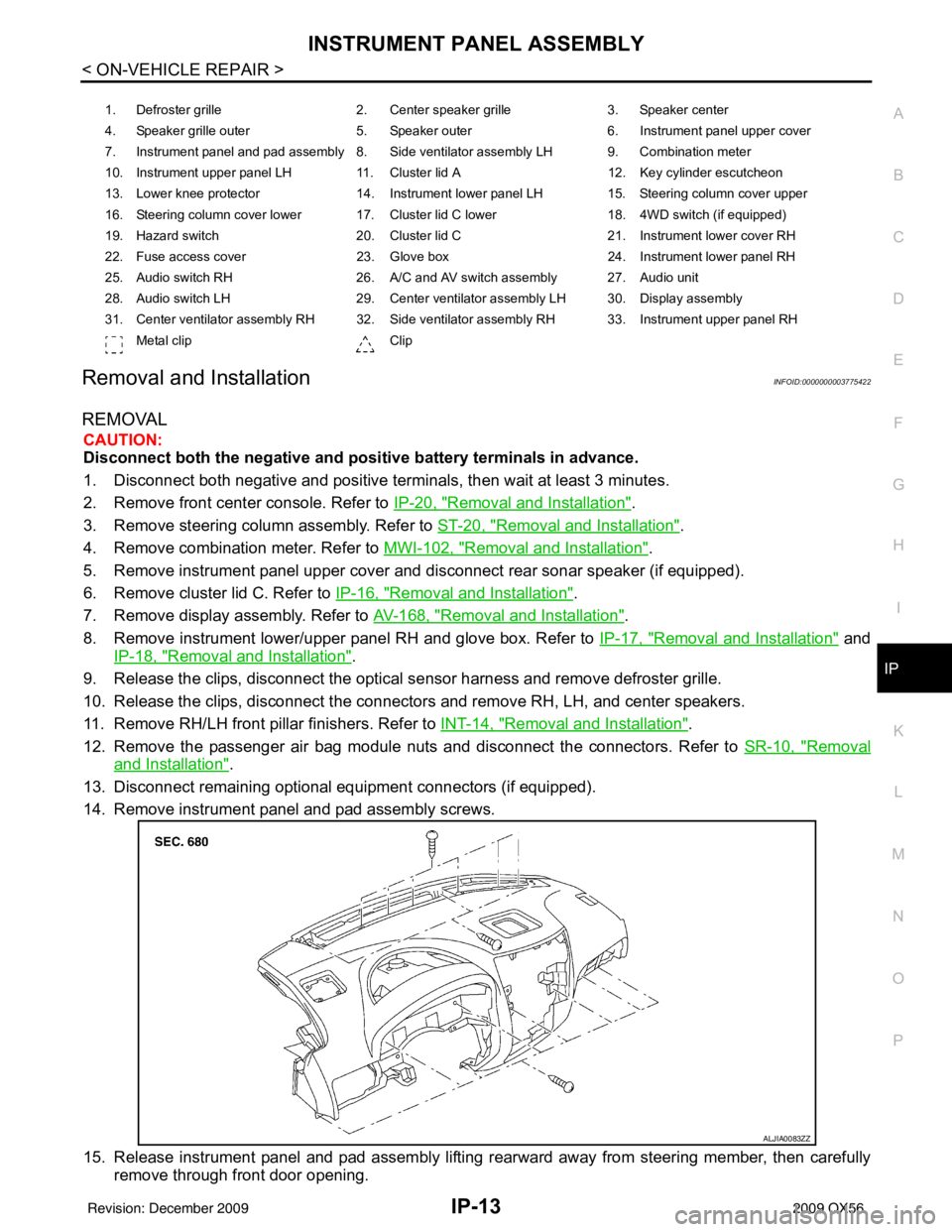
O P
Removal and InstallationINFOID:0000000003775422
REMOVAL
CAUTION:
Disconnect both the negative and positive battery terminals in advance.
1. Disconnect both negative and positive terminal s, then wait at least 3 minutes.
2. Remove front center console. Refer to IP-20, "
Removal and Installation".
3. Remove steering column assembly. Refer to ST-20, "
Removal and Installation".
4. Remove combination meter. Refer to MWI-102, "
Removal and Installation".
5. Remove instrument panel upper cover and disconnect rear sonar speaker (if equipped).
6. Remove cluster lid C. Refer to IP-16, "
Removal and Installation".
7. Remove display assembly. Refer to AV-168, "
Removal and Installation".
8. Remove instrument lower/upper panel RH and glove box. Refer to IP-17, "
Removal and Installation" and
IP-18, "
Removal and Installation".
9. Release the clips, disconnect the optical sensor harness and remove defroster grille.
10. Release the clips, disconnect the connectors and remove RH, LH, and center speakers.
11. Remove RH/LH front pillar finishers. Refer to INT-14, "
Removal and Installation".
12. Remove the passenger air bag module nuts and disconnect the connectors. Refer to SR-10, "
Removal
and Installation".
13. Disconnect remaining optional equipment connectors (if equipped).
14. Remove instrument panel and pad assembly screws.
15. Release instrument panel and pad assembly lifting rearward away from steering member, then carefully remove through front door opening.
1. Defroster grille 2. Center speaker grille3. Speaker center
4. Speaker grille outer 5. Speaker outer6. Instrument panel upper cover
7. Instrument panel and pad assembly 8. Side ventilator assembly LH 9. Combination meter
10. Instrument upper panel LH 11. Cluster lid A 12. Key cylinder escutcheon
13. Lower knee protector 14. Instrument lower panel LH 15. Steering column cover upper
16. Steering column cover lower 17. Cluster lid C lower 18. 4WD switch (if equipped)
19. Hazard switch 20. Cluster lid C21. Instrument lower cover RH
22. Fuse access cover 23. Glove box 24. Instrument lower panel RH
25. Audio switch RH 26. A/C and AV switch assembly 27. Audio unit
28. Audio switch LH 29. Center ventilator assembly LH 30. Display assembly
31. Center ventilator assembly RH 32. Side ventilator assembly RH 33. Instrument upper panel RH Metal clip Clip
ALJIA0083ZZ
Revision: December 20092009 QX56
Page 2560 of 4171
IP-16
< ON-VEHICLE REPAIR >
CLUSTER LID C
CLUSTER LID C
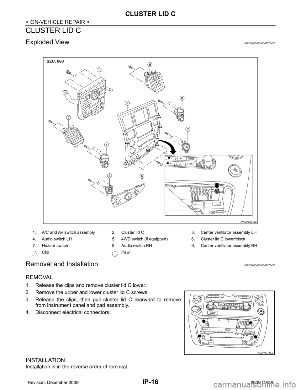
Exploded ViewINFOID:0000000003775425
Removal and InstallationINFOID:0000000003775426
REMOVAL
1. Release the clips and remove cluster lid C lower.
2. Remove the upper and lower cluster lid C screws.
3. Release the clips, then pull cluster lid C rearward to removefrom instrument panel and pad assembly.
4. Disconnect electrical connectors.
INSTALLATION
Installation is in the reverse order of removal.
1. A/C and AV switch assembly 2. Cluster lid C 3. Center ventilator assembly LH
4. Audio switch LH 5. 4WD switch (if equipped)6. Cluster lid C lower/clock
7. Hazard switch 8. Audio switch RH9. Center ventilator assembly RH
Clip Pawl
AWJIA0237ZZ
ALJIA0078ZZ
Revision: December 20092009 QX56
Page 2571 of 4171

LAN-2
MAIN LINE BETWEEN TCM AND LASER
CIRCUIT .............................................................
63
Diagnosis Procedure ........................................... ...63
MAIN LINE BETWEEN LASER AND ICC CIR-
CUIT ...................................................................
64
Diagnosis Procedure ........................................... ...64
MAIN LINE BETWEEN ICC AND ADP CIR-
CUIT ...................................................................
65
Diagnosis Procedure ........................................... ...65
MAIN LINE BETWEEN ADP AND AV CIR-
CUIT ...................................................................
66
Diagnosis Procedure ........................................... ...66
MAIN LINE BETWEEN AV AND DLC CIR-
CUIT ...................................................................
67
Diagnosis Procedure ........................................... ...67
MAIN LINE BETWEEN DLC AND M&A CIR-
CUIT ...................................................................
68
Diagnosis Procedure ........................................... ...68
MAIN LINE BETWEEN M&A AND ABS CIR-
CUIT ...................................................................
69
Diagnosis Procedure ........................................... ...69
ECM BRANCH LINE CIRCUIT ..........................70
Diagnosis Procedure ........................................... ...70
TCM BRANCH LINE CIRCUIT ..........................71
Diagnosis Procedure ........................................... ...71
LASER BRANCH LINE CIRCUIT ......................72
Diagnosis Procedure ........................................... ...72
ICC BRANCH LINE CIRCUIT ............................73
Diagnosis Procedure ............................................ ...73
ADP BRANCH LINE CIRCUIT ..........................74
Diagnosis Procedure ............................................ ...74
AV BRANCH LINE CIRCUIT .............................75
Diagnosis Procedure ............................................ ...75
BCM BRANCH LINE CIRCUIT ..........................76
Diagnosis Procedure ............................................ ...76
DLC BRANCH LINE CIRCUIT ..........................77
Diagnosis Procedure ............................................ ...77
HVAC BRANCH LINE CIRCUIT ........................78
Diagnosis Procedure ............................................ ...78
I-KEY BRANCH LINE CIRCUIT ........................79
Diagnosis Procedure ............................................ ...79
M&A BRANCH LINE CIRCUIT ..........................80
Diagnosis Procedure ............................................ ...80
STRG BRANCH LINE CIRCUIT ........................81
Diagnosis Procedure ............................................ ...81
4WD BRANCH LINE CIRCUIT ..........................82
Diagnosis Procedure ............................................ ...82
ABS BRANCH LINE CIRCUIT ..........................83
Diagnosis Procedure ............................................ ...83
IPDM-E BRANCH LINE CIRCUIT .....................84
Diagnosis Procedure ............................................ ...84
CAN COMMUNICATION CIRCUIT ...................85
Diagnosis Procedure ............................................ ...85
Revision: December 20092009 QX56