2009 INFINITI QX56 4WD
[x] Cancel search: 4WDPage 3827 of 4171
A/T FLUIDTM-179
< ON-VEHICLE MAINTENANCE >
CEF
G H
I
J
K L
M A
B
TM
N
O P
ON-VEHICLE MAINTENANCE
A/T FLUID
Checking the A/T Fluid (ATF)INFOID:0000000004187473
CAUTION:
If using the vehicle for towing, the A/T fl uid must be replaced as specified. Refer to MA-8, "Introduc-
tion of Periodic Maintenance".
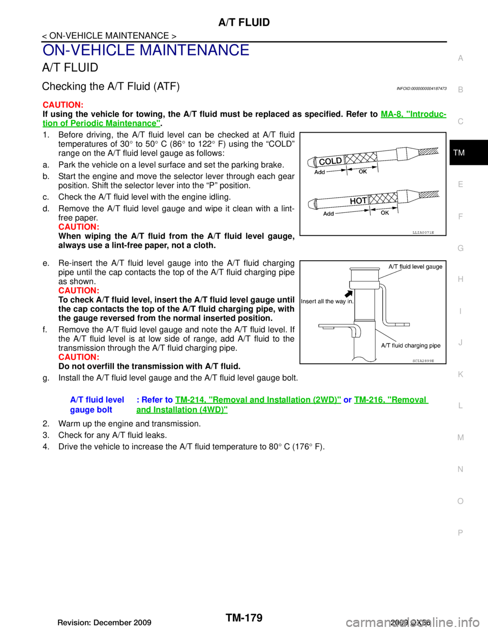
1. Before driving, the A/T fluid level can be checked at A/T fluid temperatures of 30 ° to 50 ° C (86 ° to 122 ° F) using the “COLD”
range on the A/T fluid level gauge as follows:
a. Park the vehicle on a level surface and set the parking brake.
b. Start the engine and move the selector lever through each gear position. Shift the selector lever into the “P” position.
c. Check the A/T fluid level with the engine idling.
d. Remove the A/T fluid level gauge and wipe it clean with a lint- free paper.
CAUTION:
When wiping the A/T fluid fr om the A/T fluid level gauge,
always use a lint-free paper, not a cloth.
e. Re-insert the A/T fluid level gauge into the A/T fluid charging pipe until the cap contacts the t op of the A/T fluid charging pipe
as shown.
CAUTION:
To check A/T fluid level, insert th e A/T fluid level gauge until
the cap contacts the top of the A/T fluid charging pipe, with
the gauge reversed from the normal inserted position.
f. Remove the A/T fluid level gauge and note the A/T fluid level. If the A/T fluid level is at low side of range, add A/T fluid to the
transmission through the A/T fluid charging pipe.
CAUTION:
Do not overfill the tran smission with A/T fluid.
g. Install the A/T fluid level gauge and the A/T fluid level gauge bolt.
2. Warm up the engine and transmission.
3. Check for any A/T fluid leaks.
4. Drive the vehicle to increase the A/T fluid temperature to 80 ° C (176 ° F).
LLIA0071E
A/T fluid level
gauge bolt : Refer to
TM-214, "Removal and Installation (2WD)" or TM-216, "Removal
and Installation (4WD)"
SCIA2899E
Revision: December 20092009 QX56
Page 3828 of 4171
TM-180
< ON-VEHICLE MAINTENANCE >
A/T FLUID
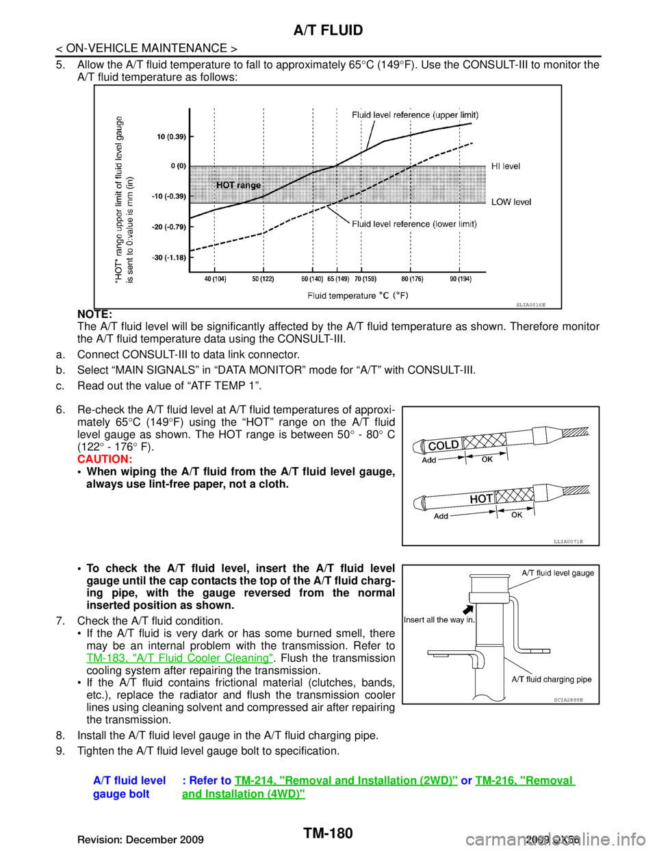
5. Allow the A/T fluid temperature to fall to approximately 65°C (149 °F). Use the CONSULT-III to monitor the
A/T fluid temperature as follows:
NOTE:
The A/T fluid level will be significantly affected by t he A/T fluid temperature as shown. Therefore monitor
the A/T fluid temperature data using the CONSULT-III.
a. Connect CONSULT-III to data link connector.
b. Select “MAIN SIGNALS” in “DATA MONI TOR” mode for “A/T” with CONSULT-III.
c. Read out the value of “ATF TEMP 1”.
6. Re-check the A/T fluid level at A/T fluid temperatures of approxi- mately 65 °C (149 °F) using the “HOT” range on the A/T fluid
level gauge as shown. The HOT range is between 50 ° - 80 ° C
(122 ° - 176 ° F).
CAUTION:
When wiping the A/T fluid from the A/T fluid level gauge,
always use lint-free paper, not a cloth.
To check the A/T fluid level , insert the A/T fluid level
gauge until the cap contacts th e top of the A/T fluid charg-
ing pipe, with the gauge reversed from the normal
inserted position as shown.
7. Check the A/T fluid condition. If the A/T fluid is very dark or has some burned smell, there
may be an internal problem with the transmission. Refer to
TM-183, "A/T Fluid Cooler Cleaning"
. Flush the transmission
cooling system after repairing the transmission.
If the A/T fluid contains frictional material (clutches, bands, etc.), replace the radiator and flush the transmission cooler
lines using cleaning solvent and compressed air after repairing
the transmission.
8. Install the A/T fluid level gauge in the A/T fluid charging pipe.
9. Tighten the A/T fluid level gauge bolt to specification.
SLIA0016E
LLIA0071E
A/T fluid level
gauge bolt : Refer to
TM-214, "Removal and Installation (2WD)" or TM-216, "Removal
and Installation (4WD)"
SCIA2899E
Revision: December 20092009 QX56
Page 3829 of 4171
A/T FLUIDTM-181
< ON-VEHICLE MAINTENANCE >
CEF
G H
I
J
K L
M A
B
TM
N
O P
Changing the A/T Fluid (ATF)INFOID:0000000005892327
CAUTION:
If using the vehicle for towing, the A/T fl uid must be replaced as specified. Refer to MA-8, "Introduc-
tion of Periodic Maintenance".
1. Drive the vehicle to warm up the A/T fluid to approximately 80 ° C (176 ° F).
2. Stop the engine.
3. Remove the A/T fluid level gauge.
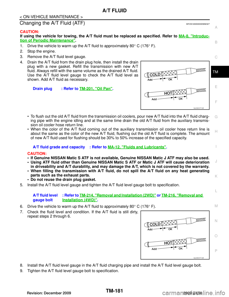
4. Drain the A/T fluid from the drai n plug hole, then install the drain
plug with a new gasket. Refill the transmission with new A/T
fluid. Always refill with the same volume as the drained A/T fluid.
Use the A/T fluid level gauge to check the A/T fluid level as
shown. Add A/T fluid as necessary.
To flush out the old A/T fluid from the transmission o il coolers, pour new A/T fluid into the A/T fluid charg-
ing pipe with the engine idling and at the same time drain the old A/T fluid from the auxiliary transmis-
sion oil cooler hose return line.
When the color of the A/T fluid coming out of the aux iliary transmission oil cooler hose return line is
about the same as the color of the new A/T fluid, flushing out the old A/T fluid is complete. The amount
of new A/T fluid used for flushing should be 30% to 50% increase of the specified capacity.
CAUTION:
If Genuine NISSAN Matic S ATF is not available, Genuine NISSAN Matic J ATF may also be used.
Using ATF fluid other than Genuine NISSAN Matic S ATF or Matic J ATF will cause deterioration
in driveability and A/T durability, and may damage the A/T, which is not covered by the warranty.
When filling the transmission with A/T fluid, do not spill the A/T fluid on any heat generating
parts such as the exhaust parts.
Do not reuse the drain plug gasket.
5. Install the A/T fluid level gauge and tighten t he A/T fluid level gauge bolt to specification.
6. Drive the vehicle to warm up the A/T fluid to approximately 80 ° C (176 ° F).
7. Check the fluid level and condition. If the A/T fluid is still dirty, repeat steps 2 through 6.
8. Install the A/T fluid level gauge in the A/T fluid charging pipe and install the A/T fluid level gauge bolt.
9. Tighten the A/T fluid level gauge bolt to specification. Drain plug : Refer to
TM-201, "Oil Pan"
.
LLIA0071E
A/T fluid grade and capacity : Refer to MA-12, "Fluids and Lubricants".
A/T fluid level
gauge bolt : Refer to
TM-214, "Removal and Installation (2WD)"
or TM-216, "Removal and
Installation (4WD)".
LLIA0071E
Revision: December 20092009 QX56
Page 3830 of 4171

TM-182
< ON-VEHICLE MAINTENANCE >
A/T FLUID
A/T fluid level
gauge bolt: Refer to
TM-214, "Removal and Installation (2WD)" or TM-216, "Removal and
Installation (4WD)".
Revision: December 20092009 QX56
Page 3845 of 4171
AIR BREATHER HOSETM-197
< ON-VEHICLE REPAIR >
CEF
G H
I
J
K L
M A
B
TM
N
O P
AIR BREATHER HOSE
2WD
2WD : Removal and InstallationINFOID:0000000005892370
CAUTION:
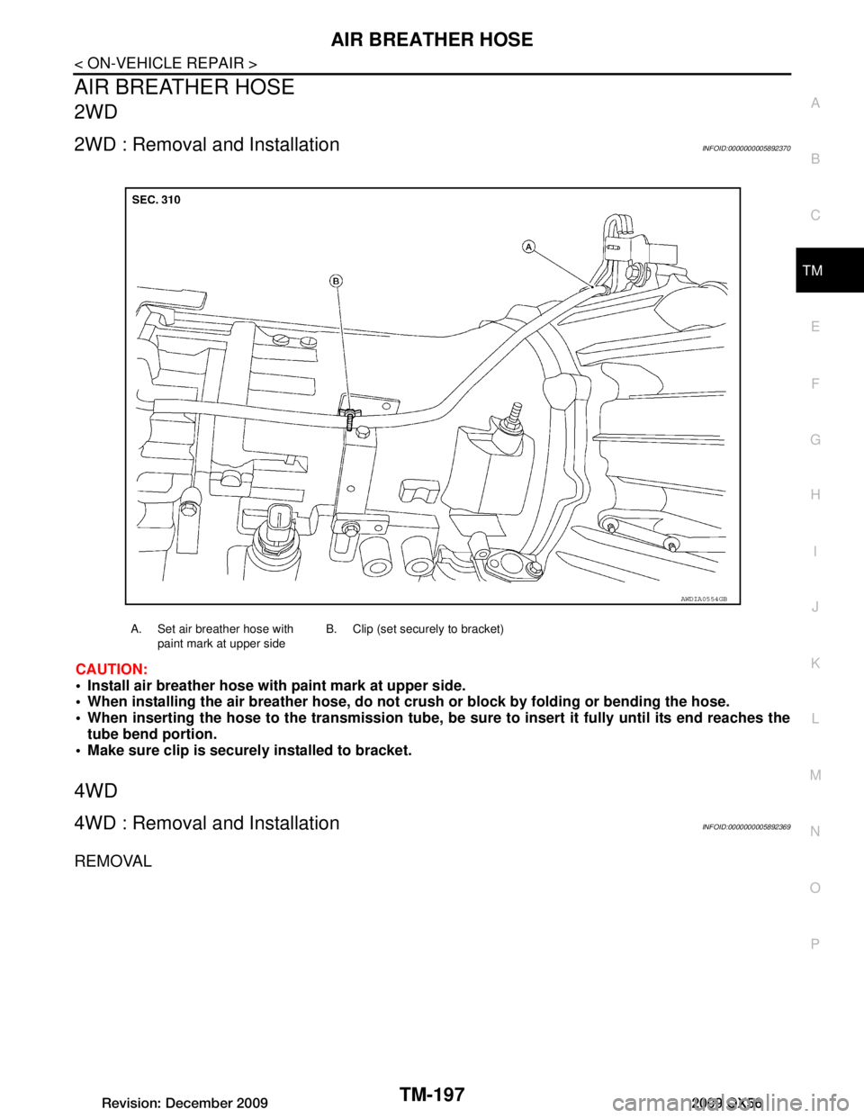
Install air breather hose with paint mark at upper side.
When installing the air breather hose, do not crush or block by folding or bending the hose.
When inserting the hose to the tran smission tube, be sure to insert it fully until its end reaches the
tube bend portion.
Make sure clip is securely installed to bracket.
4WD
4WD : Removal and InstallationINFOID:0000000005892369
REMOVAL
A. Set air breather hose with
paint mark at upper side B. Clip (set securely to bracket)
AWDIA0554GB
Revision: December 20092009 QX56
Page 3860 of 4171
TM-212
< ON-VEHICLE REPAIR >
REAR OIL SEAL
REAR OIL SEAL
Rear Oil SealINFOID:0000000004187482
REMOVAL AND INSTALLATION
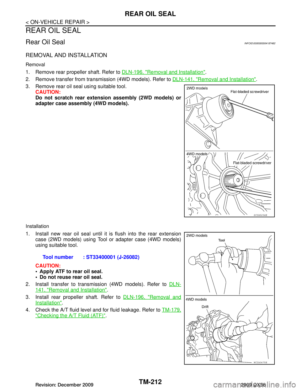
Removal
1. Remove rear propeller shaft. Refer to DLN-196, "Removal and Installation".
2. Remove transfer from transmission (4WD models). Refer to DLN-141, "Removal and Installation"
.
3. Remove rear oil seal using suitable tool. CAUTION:
Do not scratch rear extension assembly (2WD models) or
adapter case assembly (4WD models).
Installation
1. Install new rear oil seal until it is flush into the rear extension
case (2WD models) using Tool or adapter case (4WD models)
using suitable tool.
CAUTION:
Apply ATF to rear oil seal.
Do not reuse rear oil seal.
2. Install transfer to transmission (4WD models). Refer to DLN-
141, "Removal and Installation".
3. Install rear propeller shaft. Refer to DLN-196, "Removal and
Installation".
4. Check the A/T fluid level and for fluid leakage. Refer to TM-179,
"Checking the A/T Fluid (ATF)".
SCIA5254E
Tool number : ST33400001 (J-26082)
WCIA0475E
Revision: December 20092009 QX56
Page 3864 of 4171
TM-216
< REMOVAL AND INSTALLATION >
TRANSMISSION ASSEMBLY
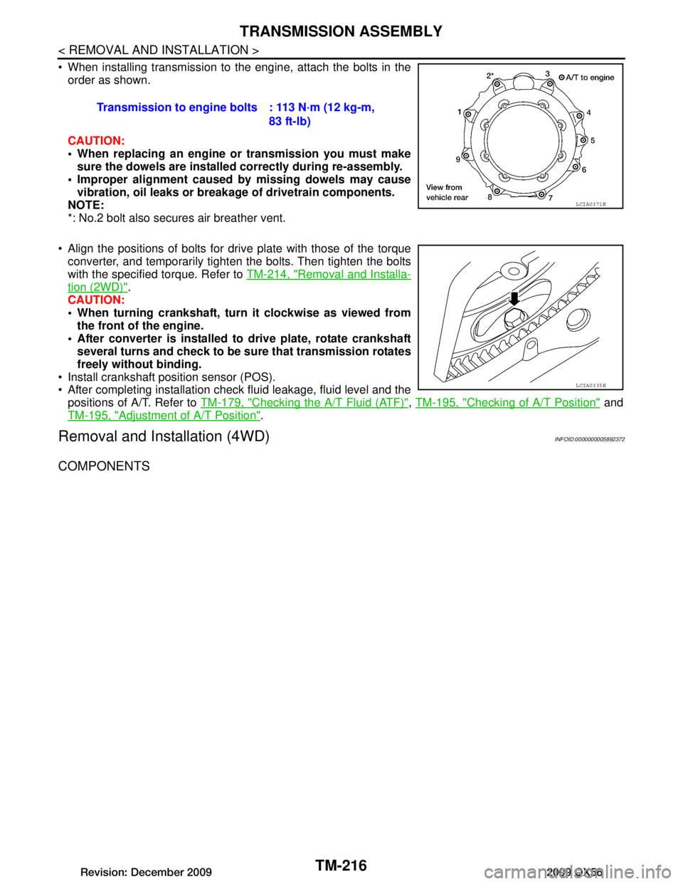
When installing transmission to the engine, attach the bolts in theorder as shown.
CAUTION:
When replacing an engine or transmission you must make
sure the dowels are installe d correctly during re-assembly.
Improper alignment caused by missing dowels may cause
vibration, oil leaks or breakage of drivetrain components.
NOTE:
*: No.2 bolt also secures air breather vent.
Align the positions of bolts for drive plate with those of the torque converter, and temporarily tight en the bolts. Then tighten the bolts
with the specified torque. Refer to TM-214, "Removal and Installa-
tion (2WD)".
CAUTION:
When turning crankshaft, turn it clockwise as viewed from
the front of the engine.
After converter is installed to drive plate, rotate crankshaft several turns and check to be su re that transmission rotates
freely without binding.
Install crankshaft position sensor (POS).
After completing installation check fluid leakage, fluid level and the positions of A/T. Refer to TM-179, "Checking the A/T Fluid (ATF)"
, TM-195, "Checking of A/T Position" and
TM-195, "Adjustment of A/T Position"
.
Removal and Installation (4WD)INFOID:0000000005892372
COMPONENTS
Transmission to engine bolts : 113 N·m (12 kg-m,
83 ft-lb)
LCIA0371E
LCIA0335E
Revision: December 20092009 QX56
Page 3866 of 4171
TM-218
< REMOVAL AND INSTALLATION >
TRANSMISSION ASSEMBLY
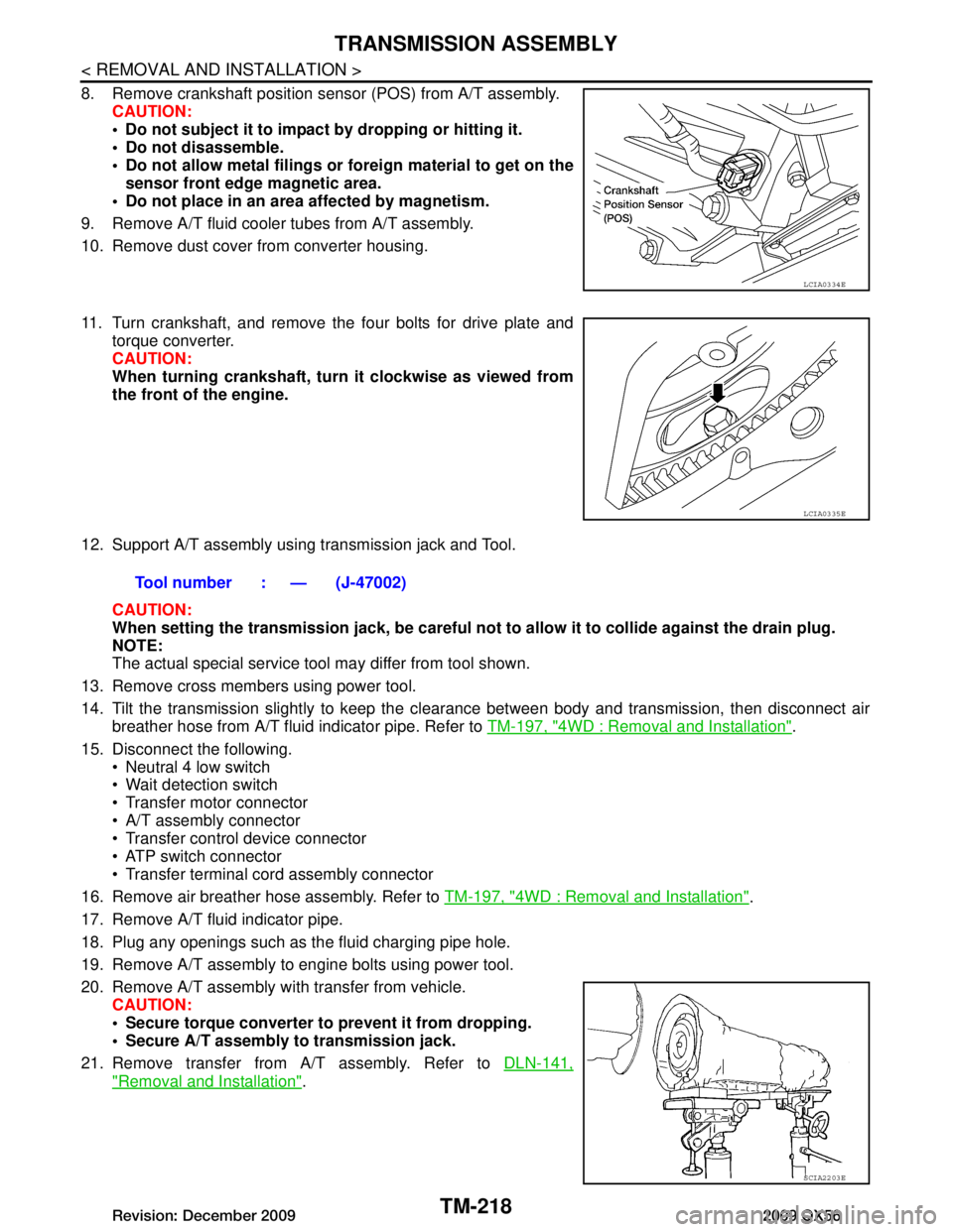
8. Remove crankshaft position sensor (POS) from A/T assembly.CAUTION:
Do not subject it to impact by dropping or hitting it.
Do not disassemble.
Do not allow metal filings or fo reign material to get on the
sensor front edge magnetic area.
Do not place in an area affected by magnetism.
9. Remove A/T fluid cooler tubes from A/T assembly.
10. Remove dust cover from converter housing.
11. Turn crankshaft, and remove the four bolts for drive plate and torque converter.
CAUTION:
When turning crankshaft, turn it clockwise as viewed from
the front of the engine.
12. Support A/T assembly using transmission jack and Tool. CAUTION:
When setting the transmission jack, be careful not to allow it to collide against the drain plug.
NOTE:
The actual special service tool may differ from tool shown.
13. Remove cross members using power tool.
14. Tilt the transmission slightly to keep the cl earance between body and transmission, then disconnect air
breather hose from A/T fluid indicator pipe. Refer to TM-197, "4WD : Removal and Installation"
.
15. Disconnect the following. Neutral 4 low switch
Wait detection switch
Transfer motor connector
A/T assembly connector
Transfer control device connector
ATP switch connector
Transfer terminal cord assembly connector
16. Remove air breather hose assembly. Refer to TM-197, "4WD : Removal and Installation"
.
17. Remove A/T fluid indicator pipe.
18. Plug any openings such as the fluid charging pipe hole.
19. Remove A/T assembly to engine bolts using power tool.
20. Remove A/T assembly with transfer from vehicle. CAUTION:
Secure torque converter to prevent it from dropping.
Secure A/T assembly to transmission jack.
21. Remove transfer from A/T assembly. Refer to DLN-141,
"Removal and Installation".
LCIA0334E
LCIA0335E
Tool number : — (J-47002)
SCIA2203E
Revision: December 20092009 QX56