Page 8 of 308
Your vehicle at a glance
2
2
INTERIOR OVERVIEW
1. Door lock/unlock button ............................4-8
2. Outside rearview mirror control switch* .....4-31
3. Central door lock switch ...........................4-9
4. Power window lock switch ......................4-16
5. Power window switches ..........................4-13
6. Boot lid release button............................4-12
7. Fuse box ..................................................7-42
8. Rear fog lamp switch ..............................4-49
9. ESP OFF button* ....................................5-20
10. Instrument panel illumination................4-34
11. Steering wheel tilt .................................4-26
12. Bonnet release lever.............................4-17
13. Brake pedal ..........................................5-15
14. Accelerator pedal....................................5-5
15. Hand brake lever ..................................5-16
* : if equipped
OHD006001R
Page 38 of 308

329
Safety system of your vehicle
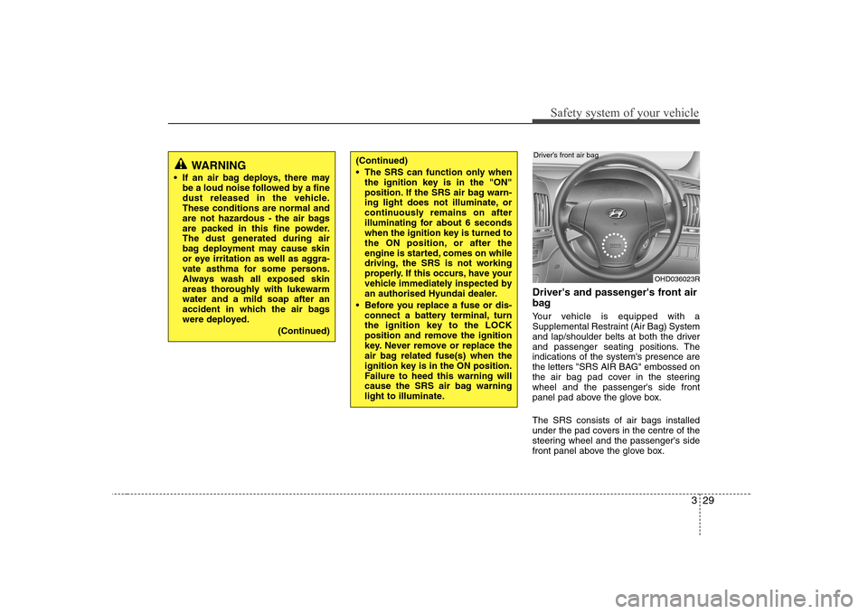
Driver's and passenger's front air
bag
Your vehicle is equipped with a
Supplemental Restraint (Air Bag) System
and lap/shoulder belts at both the driver
and passenger seating positions. Theindications of the system's presence are
the letters "SRS AIR BAG" embossed on
the air bag pad cover in the steeringwheel and the passenger's side front
panel pad above the glove box. The SRS consists of air bags installed
under the pad covers in the centre of the
steering wheel and the passenger's side
front panel above the glove box.
WARNING
If an air bag deploys, there may be a loud noise followed by a fine
dust released in the vehicle.These conditions are normal and
are not hazardous - the air bags
are packed in this fine powder.
The dust generated during air
bag deployment may cause skin
or eye irritation as well as aggra-
vate asthma for some persons.
Always wash all exposed skin
areas thoroughly with lukewarmwater and a mild soap after an
accident in which the air bags
were deployed.
(Continued)(Continued)
The SRS can function only whenthe ignition key is in the "ON"
position. If the SRS air bag warn-
ing light does not illuminate, or
continuously remains on after
illuminating for about 6 seconds
when the ignition key is turned to
the ON position, or after the
engine is started, comes on while
driving, the SRS is not working
properly. If this occurs, have your
vehicle immediately inspected by
an authorised Hyundai dealer.
Before you replace a fuse or dis- connect a battery terminal, turn
the ignition key to the LOCK
position and remove the ignition
key. Never remove or replace the
air bag related fuse(s) when the
ignition key is in the ON position.
Failure to heed this warning will
cause the SRS air bag warning
light to illuminate.
OHD036023R
Driver’s front air bag
Page 227 of 308
Maintenance
2
7
ENGINE COMPARTMENT
OHD076002R
1. Engine coolant reservoir
2. Engine oil filler cap
3. Brake fluid reservoir
4. Air cleaner
5. Fuse box
6. Negative battery terminal
7. Positive battery terminal
8. Auto transaxle oil dipstick*
9. Radiator cap
10. Engine oil dipstick
11. Windshield washer fluid reservoir
12. Clutch fluid reservoir*
* : if equipped
■■
Petrol Engine (2.0L)
Page 267 of 308
Maintenance
42
7
Inner panel fuse replacement
1. Turn the ignition switch and all other
switches off.
2. Open the fuse panel cover. 3. Pull the suspected fuse straight out.
Use the removal tool provided on the
main fuse box in the engine compart-ment.
4. Check the removed fuse; replace it if it is blown.
5. Push in a new fuse of the same rating, and make sure it fits tightly in the clips.
If it fits loosely, consult an authorised
Hyundai dealer.
If you do not have a spare, use a fuse of the same rating from a circuit you may
not need for operating the vehicle, such as the cigar lighter fuse.
If the headlights or other electrical com-
ponents do not work and the fuses are
OK, check the fuse block in the engine
compartment. If a fuse is blown, it mustbe replaced.
OHD076025R
Driver’s side panel
OHD076026
Page 269 of 308
Maintenance
44
7
Main fuse
If the main fuse is blown, it must be
removed as follows:
1. Disconnect the negative battery cable.
2. Remove the nuts shown in the picture
above.
3. Replace the fuse with a new one of the same rating.
4. Reinstall in the reverse order of removal. ✽
✽
NOTICE
If the main fuse is blown, consult an
Authorised Hyundai Dealer.CAUTION
After checking the fuse box in the
engine compartment, securelyinstall the fuse box cover. If not, electrical failures may occur from
water leaking in.
OHD076030
Page 270 of 308
745
Maintenance
✽✽NOTICE
Not all fuse panel descriptions in this
manual may be applicable to your vehi-cle. It is accurate at the time of printing.When you inspect the fuse box on your
vehicle, refer to the fuse box label.
Engine compartment
OHD076031R/OHD076032
Fuse/Relay panel description
Inside the fuse/relay box covers, you can find the fuse/relay label describing fuse/relay
name and capacity.
Driver’s side panel
Page 272 of 308
747
Maintenance
Description Fuse ratingProtected component
CLUSTER 10A Instrument cluster
A/BAG 15A SRS control module
IGN 1 15A EPS module, ESP switch
SPARE 15A (Spare)
TAIL RH 10A Head lamp(RH), Glove box lamp, Rear combination lamp(RH), License lamp
TAIL LH 10A Head lamp(LH), Power window main switch, Rear combination lamp(LH), License lamp
Page 273 of 308

Maintenance
48
7
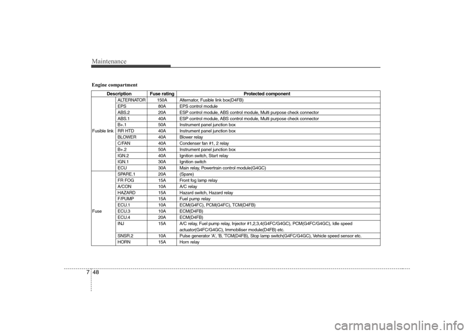
Engine compartment
Description Fuse rating Protected component
ALTERNATOR 150A Alternator, Fusible link box(D4FB)
EPS 80A EPS control module
ABS.2 20A ESP control module, ABS control module, Multi purpose check connector
ABS.1 40A ESP control module, ABS control module, Multi purpose check connector
B+.1 50A Instrument panel junction box
Fusible link RR HTD 40A Instrument panel junction box BLOWER 40A Blower relay
C/FAN 40A Condenser fan #1, 2 relay
B+.2 50A Instrument panel junction box
IGN.2 40A Ignition switch, Start relay
IGN.1 30A Ignition switch
ECU 30A Main relay, Powertrain control module(G4GC)
SPARE.1 20A (Spare)
FR FOG 15A Front fog lamp relay
A/CON 10A A/C relay
HAZARD 15A Hazard switch, Hazard relay
F/PUMP 15A Fuel pump relay
ECU.1 10A ECM(G4FC), PCM(G4FC), TCM(D4FB)
Fuse ECU.3 10A ECM(D4FB) ECU.4 20A ECM(D4FB)
INJ 15A A/C relay, Fuel pump relay, Injector #1,2,3,4(G4FC/G4GC), PCM(G4FC/G4GC), Idle speed actuator(G4FC/G4GC), Immobiliser module(D4FB) etc.
SNSR.2 10A Pulse generator 'A', 'B, 'TCM(D4FB), Stop lamp switch(G4FC/G4GC), Vehicle speed sensor etc.
HORN 15A Horn relay