2009 Hyundai Accent horn
[x] Cancel search: hornPage 9 of 232
F9
CAUTION:
When installing a container of liquid air freshener inside the vehicle, do not place it near the instrument cluster nor on the instrument panel pad surface. If there is any leakage from the air freshener onto these areas (Instrument cluster, instrument panel pad or air ventilator), it may damage these parts. If the liquid from air freshener does leak onto these areas, wash them withwater immediately.
!
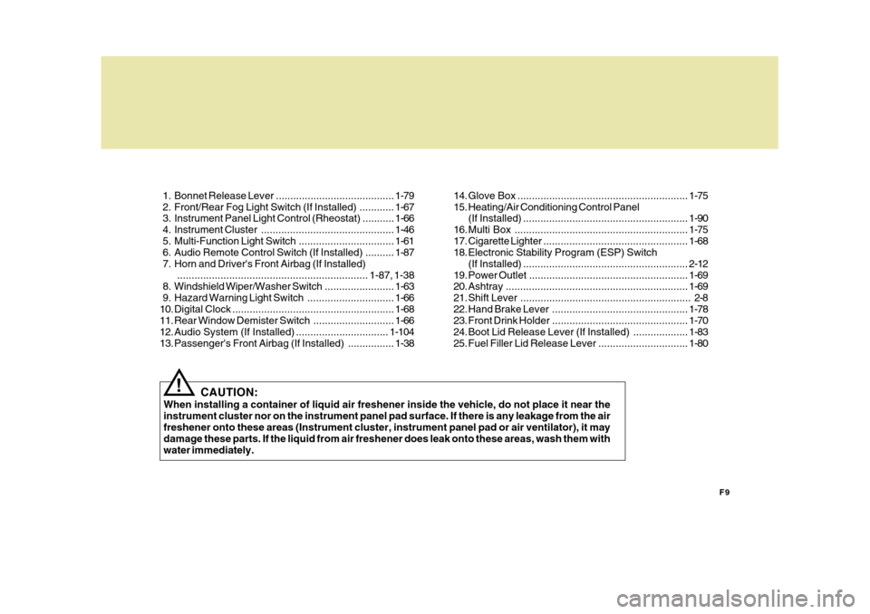
1. Bonnet Release Lever .........................................
1-79
2. Front/Rear Fog Light Switch (If Installed) ............ 1-67
3. Instrument Panel Light Control (Rheostat) ........... 1-66
4. Instrument Cluster.............................................. 1-46
5. Multi-Function Light Switch................................. 1-61
6. Audio Remote Control Switch (If Installed) .......... 1-87
7. Horn and Driver's Front Airbag (If Installed) .................................................................. 1-87, 1-38
8. Windshield W iper/Washer Switch ........................1-63
9. Hazard Warning Light Switch.............................. 1-66
10. Digital Clock ........................................................ 1-68
11. Rear Window Demist er Switch ............................ 1-66
12. Audio System (If Installed) ................................ 1-104
13. Passenger's Front Airbag (If Installed) ................1-3814. Glove Box ...........................................................
1-75
15. Heating/Air Conditioning Control Panel (If Installed) ......................................................... 1-90
16. Multi Box ............................................................ 1-75
17. Cigarette Lighter .................................................. 1-68
18. Electronic Stability Program (ESP) Switch
(If Installed) ......................................................... 2-12
19. Power Outlet ....................................................... 1-69
20. Ashtray ............................................................... 1-69
21. Shift Lever ........................................................... 2-8
22. Hand Brake Lever ............................................... 1-78
23. Front Drink Holder ............................................... 1-70
24. Boot Lid Release Lever (If Installed) ................... 1-83
25. Fuel Filler Lid Release Lever ...............................1-80
Page 20 of 232
1
FEATURES OF YOUR HYUNDAI
9
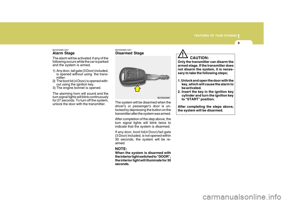
B070D03MC-DAT Disarmed Stage
B070C02MC-DATAlarm Stage The alarm will be activated if any of the following occurs while the car is parked and the system is armed.
1) Any door, tail gate (3 Door) included,
is opened without using the trans- mitter.
2) The boot lid (4 Door) is opened with-
out using the ignition key.
3) The engine bonnet is opened. The alarming horn will sound and the turn signal lights will blink continuouslyfor 27 seconds. To turn off the system, unlock the door with the transmitter. The system will be disarmed when the driver's or passenger's door is un- locked by depressing the button on thetransmitter after the system was armed. After completion of the step above, the turn signal lights will blink twice to indicate that the system is disarmed. If any door, boot lid(4 Door)/tail gate (3 Door) included, is not opened within 30 seconds, the system will be re-armed. NOTE: When the system is disarmed with the interior light switched to "DOOR",the interior light will illuminate for 30 seconds.
B070D02AMCCAUTION:
Only the transmitter can disarm the armed stage. If the transmitter doesnot disarm the system, it is neces- sary to take the following steps; 1. Unlock and open the door with the key, which will cause the alarm to be activated.
2. Insert the key in the ignition key cylinder and turn the ignition keyto "START" position.
After completing the steps above,the system will be disarmed.
!
Page 98 of 232
1
FEATURES OF YOUR HYUNDAI
87HORN
B610B01L-GAT
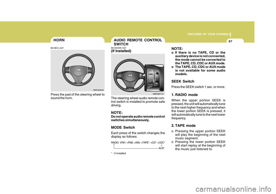
Press the pad of the steering wheel to sound the horn.
OMC025046
AUDIO REMOTE CONTROL SWITCH
B610A02MC-GAT (If Installed) The steering wheel audio remote con- trol switch is installed to promote safe driving. NOTE: Do not operate audio remote control switches simultaneously. MODE Switch Each press of the switch changes the display as follows: * : if installed OMC025110
NOTE: o If there is no TAPE, CD or the
auxiliary device is not connected, the mode cannot be converted tothe TAPE, CD, CDC or AUX mode.
o The TAPE, CD, CDC or AUX mode
is not available for some audiomodels.
SEEK Switch Press the SEEK switch 1 sec. or more.
1. RADIO mode When the upper portion SEEK is pressed, the unit will automatically tuneto the next higher frequency and when the lower portion SEEK is pressed, it will automatically tune to the next lowerfrequency.
2. TAPE mode
o Pressing the upper portion SEEK will play the beginning of the next music segment.
o Pressing the lower portion SEEK will start replay at the beginning ofthe music just listened to.
�
RADIO (FM1 �FM2 �AM) �TAPE* �CD* �CDC*�
AUX*
Page 142 of 232
2
DRIVING YOUR HYUNDAI
15
2
DRIVING YOUR HYUNDAI
15
CAUTION:
1. The rear parking assist warning may not sound sequentially de- pending on the speed and shapesof the objects detected.
2. The rear parking assist system
may malfunction if the vehiclebumper height or sensor installa- tion has been modified or dam- aged. Any non-factory installedequipment or accessories may also interfere with the sensor per- formance.
3. The sensor may not recognise objects less than 15 in. (40 cm)from the sensor, or it may sensean incorrect distance. Use cau- tion.
4. When the sensor is frozen or stained with snow, dirt, or water,the sensor may be inoperative until the stains are removed using asoft cloth.
5. Do not push, scratch or strike the
sensor. Sensor damage couldoccur.
!
4. Objects generating excessive noise
(vehicle horns, loud motorcycle en- gines, or truck air brakes) are within range of the sensor.
5. Heavy rain or water spray exists.
6. Wireless transmitters or mobile phones are within range of the sen-sor.
7. The sensor is covered with snow. 8. Trailer towing The detecting range may decrease when: 1. The sensor is stained with foreign matter such as snow or water. (The sensing range will return to normal when removed.)
2. Outside air temperature is extremely hot or cold.
The following objects may not be recognised by the sensor: 1. Sharp or slim objects such as ropes, chains or small poles.
2. Objects which tend to absorb the
sensor frequency such as clothes,spongy material or snow.
3. Undetectable objects smaller than 1
m (40 in.) and narrower than 14 cm (6in.) in diameter. CAUTION:
This system can only sense objects within the range and location of the sensors; It can not detect objects inother areas where sensors are not installed. Also, small or slim ob- jects, such as poles or objects lo-cated between sensors may not be detected by the sensors. Always visually check behind thevehicle when backing up. Be sure to inform any drivers of the vehicle that may be unfamiliar withthe system regarding the systems capabilities and limitations. Your new vehicle warranty does notcover any accidents or damage to the vehicle or its occupants due to a rear parking assist system malfunc-tion. Always drive safely and cau- tiously.!
Page 184 of 232
6
DO-IT-YOURSELF MAINTENANCE
3GENERAL CHECKS
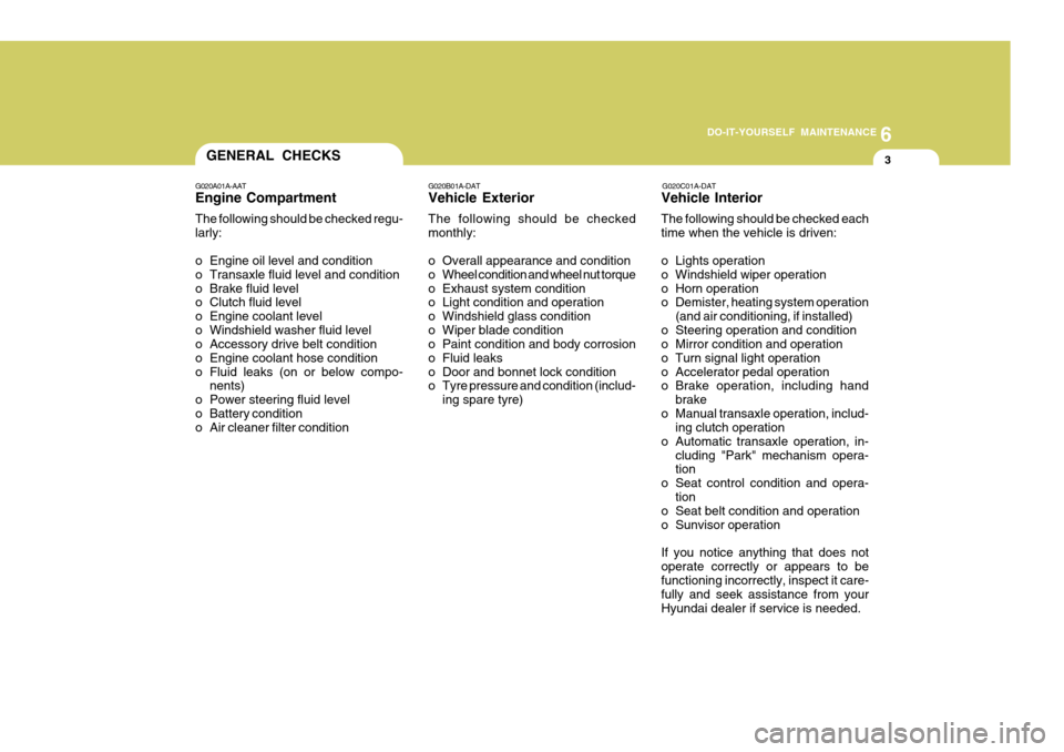
G020A01A-AAT Engine Compartment The following should be checked regu- larly:
o Engine oil level and condition
o Transaxle fluid level and condition
o Brake fluid level
o Clutch fluid level
o Engine coolant level
o Windshield washer fluid level
o Accessory drive belt condition
o Engine coolant hose condition
o Fluid leaks (on or below compo- nents)
o Power steering fluid level
o Battery condition
o Air cleaner filter condition G020C01A-DAT Vehicle Interior The following should be checked each time when the vehicle is driven:
o Lights operation
o Windshield wiper operation
o Horn operation
o Demister, heating system operation
(and air conditioning, if installed)
o Steering operation and condition
o Mirror condition and operation
o Turn signal light operation
o Accelerator pedal operation
o Brake operation, including hand
brake
o Manual transaxle operation, includ- ing clutch operation
o Automatic transaxle operation, in- cluding "Park" mechanism opera-tion
o Seat control condition and opera- tion
o Seat belt condition and operation
o Sunvisor operation If you notice anything that does not operate correctly or appears to befunctioning incorrectly, inspect it care- fully and seek assistance from your Hyundai dealer if service is needed.
G020B01A-DAT Vehicle Exterior The following should be checked monthly:
o Overall appearance and condition
o Wheel condition and wheel nut torque
o Exhaust system condition
o Light condition and operation
o Windshield glass condition
o Wiper blade condition
o Paint condition and body corrosion
o Fluid leaks
o Door and bonnet lock condition
o Tyre pressure and condition (includ-
ing spare tyre)
Page 211 of 232
6 DO-IT-YOURSELF MAINTENANCE
30FUSE PANEL DESCRIPTION
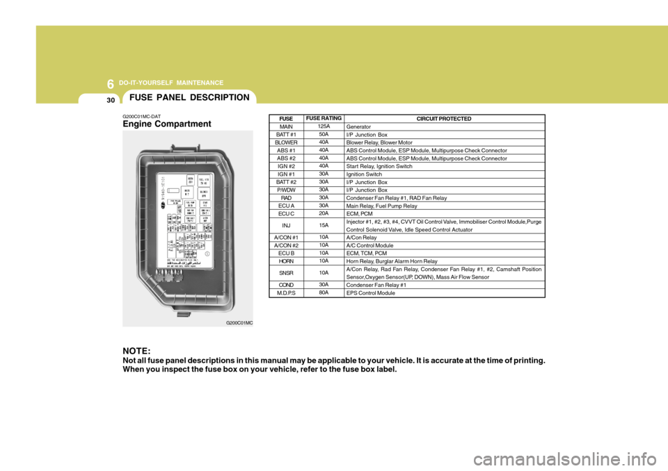
G200C01MC-DAT Engine Compartment NOTE: Not all fuse panel descriptions in this manual may be applicable to your vehicle. It is accurate at the time of printing. When you inspect the fuse box on your vehicle, refer to the fuse box label.
G200C01MC FUSE RATING
125A50A 40A 40A 40A40A 30A 30A30A 30A 30A20A 15A10A 10A 10A10A 10A30A 80A CIRCUIT PROTECTED
GeneratorI/P Junction Box
Blower Relay, Blower MotorABS Control Module, ESP Module, Multipurpose Check Connector ABS Control Module, ESP Module, Multipurpose Check Connector
Start Relay, Ignition SwitchIgnition Switch I/P Junction Box I/P Junction BoxCondenser Fan Relay #1, RAD Fan Relay
Main Relay, Fuel Pump Relay ECM, PCM
Injector #1, #2, #3, #4, CVVT Oil Control Valve, Immobiliser Control Module,Purge
Control Solenoid Valve, Idle Speed Control Actuator A/Con RelayA/C Control ModuleECM, TCM, PCM
Horn Relay, Burglar Alarm Horn Relay
A/Con Relay, Rad Fan Relay, Condenser Fan Relay #1, #2, Camshaft Position
Sensor,Oxygen Sensor(UP, DOWN), Mass Air Flow Sensor Condenser Fan Relay #1 EPS Control Module
MAIN
BATT #1
BLOWER
ABS #1 ABS #2IGN #2 IGN #1
BATT #2 P/WDW
RAD
ECU A ECU C
INJ
A/CON #1 A/CON #2 ECU BHORN
SNSR
COND
M.D.P.S
FUSE
Page 230 of 232
10
INDEX
3
E Electronic Stability Program (ESP) ...........................2-12
Emission Contro l System ............................................ 7-2
Engine Before starting the engine ........................................ 2-3Compartment ............................................................ 6-2
Coolant ..................................................................... 6-7
If the engine overheats ............................................. 3-4
Number ..................................................................... 8-3
Oil ............................................................................. 6-4 Starting ..................................................................... 2-5
Engine Exhaust Can Be Dangerous ............................ 2-2
FFog Light Front ....................................................................... 1-67
Rear ........................................................................ 1-67
Front Seats Adjustable front seats ............................................. 1-14
Adjustable headrests .............................................. 1-15
Adjusting seat forward and rearward .......................1-14
Adjusting seatback angle ....................................... 1-14
Fuel
Capacity ................................................................... 9-2
Gauge ..................................................................... 1-55
Recommendations .................................................... 1-2
Fuel Filler Lid
Remote release ...................................................... 1-80
Fuses ........................................................................ 6-17
Fuse Panel description .............................................. 6-30G General Checks
........................................................... 6-3
Glove Box ................................................................. 1-75
H Hand Brake ................................................................ 1-78
Hazard Warning System ............................................ 1-66
Headlight Aiming Adjustment..................................... 6-22
Heating and Cooling Control ......................................1-89
Heating and Ventilation .............................................. 1-90
Air flow control ........................................................ 1-91
Air intake control .................................................... 1-90
Bi-level heati ng ....................................................... 1-94
Demisting/Defogging ............................................... 1-94
Fan speed control ................................................... 1-90
Temperature control ................................................ 1-93
High-Mounted Rear Stop Light................................... 1-79
Horn ........................................................................... 1-87
IImmobiliser System ..................................................... 1-3
Instrument Cluster and Indicator Lights ..................... 1-46
Instrument Panel Light Control (Rheostat) .................1-66
Interior Light
Interior light ............................................................. 1-73
Map light ................................................................. 1-73
JJump Starting .............................................................. 3-3