Page 202 of 232

6
DO-IT-YOURSELF MAINTENANCE
21
!
G220B01A-AAT Checking Engine Cooling Fan The engine coolant fan should come on automatically if the engine coolanttemperature is high. G220C01TB-GAT Checking Condenser Cooling Fan When the air conditioning is in opera- tion, the condenser cooling fan comeson automatically, being controlled by
the engine ECU.
WARNING:
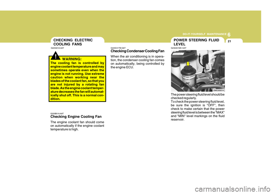
The cooling fan is controlled by engine coolant temperature and may sometimes operate even when the engine is not running. Use extremecaution when working near the blades of the coolant fan, so that you are not injured by a rotating fanblade. As the engine coolant temper- ature decreases the fan will automat- ically shut off. This is a normal con-dition. The power steering fluid level should be checked regularly. To check the power steering fluid level,be sure the ignition is "OFF", then check to make certain that the power steering fluid level is between the "MAX"and "MIN" level markings on the fluid reservoir.
CHECKING ELECTRIC COOLING FANS
G220A01A-AATPOWER STEERING FLUID LEVEL
G230A01MC-GAT
OMC055014
Page 211 of 232

6 DO-IT-YOURSELF MAINTENANCE
30FUSE PANEL DESCRIPTION
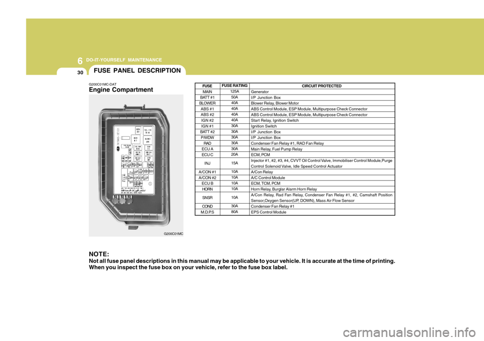
G200C01MC-DAT Engine Compartment NOTE: Not all fuse panel descriptions in this manual may be applicable to your vehicle. It is accurate at the time of printing. When you inspect the fuse box on your vehicle, refer to the fuse box label.
G200C01MC FUSE RATING
125A50A 40A 40A 40A40A 30A 30A30A 30A 30A20A 15A10A 10A 10A10A 10A30A 80A CIRCUIT PROTECTED
GeneratorI/P Junction Box
Blower Relay, Blower MotorABS Control Module, ESP Module, Multipurpose Check Connector ABS Control Module, ESP Module, Multipurpose Check Connector
Start Relay, Ignition SwitchIgnition Switch I/P Junction Box I/P Junction BoxCondenser Fan Relay #1, RAD Fan Relay
Main Relay, Fuel Pump Relay ECM, PCM
Injector #1, #2, #3, #4, CVVT Oil Control Valve, Immobiliser Control Module,Purge
Control Solenoid Valve, Idle Speed Control Actuator A/Con RelayA/C Control ModuleECM, TCM, PCM
Horn Relay, Burglar Alarm Horn Relay
A/Con Relay, Rad Fan Relay, Condenser Fan Relay #1, #2, Camshaft Position
Sensor,Oxygen Sensor(UP, DOWN), Mass Air Flow Sensor Condenser Fan Relay #1 EPS Control Module
MAIN
BATT #1
BLOWER
ABS #1 ABS #2IGN #2 IGN #1
BATT #2 P/WDW
RAD
ECU A ECU C
INJ
A/CON #1 A/CON #2 ECU BHORN
SNSR
COND
M.D.P.S
FUSE
Page 213 of 232

6 DO-IT-YOURSELF MAINTENANCE
32
FUSE RATING10A 20A10A 10A 15A 10A10A 20A 10A 15A 10A 15A 10A10A 10A 10A 10A CIRCUIT PROTECTED
Front Fog Lamp Switch, Front Fog Lamp LH, Front Fog Lamp RH,BCM Sunroof Motor Hazard SwitchOver Driver Switch, TCM(Diesel), Pulse Generator 'A'(Diesel),Pulse Generator
'B'(Diesel), Vehicle Speed Sensor
Data Link Connector, Stop Lamp Switch, P/WDW Relay,Multipurpose CheckConnector Instrument Cluster ECM, PCM, EPS Control Module, Mass Air Flow Sensor(Diesel), Fuel FilterWarning Switch(Diesel) Driver Door Lock Actuator, Assist Door Lock Actuator, BCM,Rear Door Lock
Actuator LH, Rear Door Lock Actuator RH,Driver Power Window Switch, TailGate Lock Actuator Start Relay BCM, Instrument Cluster, Generator, DRL Control ModuleIgnition Coil #1, #2, #3, #4, CondenserAudio
Luggage Lamp, Room Lamp, Vanity Lamp Switch, Digital Clock,Overhead Consol Lamp, A/C Control Module, Instrument Cluster, Rear Parking Assist Buzzer, Door Warning Switch, BCM ESP Switch, Steering Angle Sensor, ABS Control Module,ESP Module,Multipurpose Check Connector
Back-up Lamp Switch, Transaxle Range Switch DRL Control ModulePower Outside Mirror & Mirror Folding Switch
FR FOG LP S/ROOF
T/SIG LP
TCU
STOP LP
A/BAG IND ECU
C/DR LOCK START
CLUSTER IGN COIL AUDIO
(Power Connector)
MULT B/UP
(Power Connector)
ABS
B/UP LP DRL
FOLD'G
FUSE
Page 216 of 232

7
EMISSION CONTROL SYSTEMS
3CATALYTIC CONVERTER
H020A01A-DAT
(If Installed)
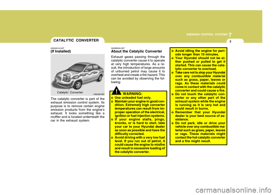
The catalytic converter is part of the
exhaust emission control system. Its purpose is to remove certain engineemission products from the engine's exhaust. It looks something like a muffler and is located underneath thecar in the exhaust system. H020B02A-DAT
About the Catalytic Converter
Exhaust gases passing through the
catalytic converter cause it to operate at very high temperatures. As a re- sult, the introduction of large amountsof unburned petrol may cause it to overheat and create a fire hazard. This can be avoided by observing the fol-lowing:
H020A01MCCatalytic Converter!WARNING:
o Use unleaded fuel only.
o Maintain your engine in good con- dition. Extremely high converter temperatures can result from im-proper operation of the electrical, ignition or fuel injection systems.
o If your engine stalls, pings, knocks, or is hard to start, takeyour car to your Hyundai dealer as soon as possible and have thedifficulty corrected.
o Avoid driving with a very low fuel
level. If you run out of petrol, it could cause the engine to misfire and result in excessive loading ofthe catalytic converter. o Avoid idling the engine for peri-
ods longer than 10 minutes.
o Your Hyundai should not be ei- ther pushed or pulled to get itstarted. This can cause the cata-lytic converter to overload.
o Take care not to stop your Hyundai over any combustible material such as grass, paper, leaves or rags. As these materials couldcome in contact with the catalytic converter and could cause a fire.
o Do not touch the catalytic con- verter or any other part of the exhaust system while the engineis running as it is very hot and could result in burns.
o Remember that your Hyundai dealer is your best source of as-sistance.
o Do not park, idle or drive your vehicle over any combustible ma- terial such as grass, paper, leavesor rags. These materials might contact the hot catalytic converter and a fire might result.
Page 226 of 232
9
VEHICLE SPECIFICATIONS
3ENGINE
Engine Type Bore x Stroke (mm) Displacement (cc) Firing orderIdle speed (RPM) Ignition timing
J070A02MC-DAT
ITEMS
N,P
D PETROL
1.6L
720 ± 100 660 ± 100
BTDC 5° ± 5°
4-Cylinder in-line DOHC
76.5 x 871,599
1 - 3 - 4 - 2