Page 446 of 578

�Î�Î�Î
�Î �Î�Î
�µ�µ
�Î
�Î�Î
T owing is Not Recommended
Number of
Occupants 2
3
4
5
6
7
8 Maximum T otal T railer Weight
Maximum T ongue Load
T owing is Not Recommended
Number of
Occupants 2
3
4
5
6
7
8 Maximum T otal T railer Weight
Maximum T ongue Load
2WD models
4WD models
Towing a Trailer
442
Total Trailer Weight and Tongue Load Limits:
3,500 lbs (1,588 kg)
3,300 lbs (1,497 kg)
3,100 lbs (1,406 kg)
3,000 lbs (1,361 kg)
2,800 lbs (1,270 kg)
2,000 lbs (907 kg) 350 lbs (159 kg)
300 lbs (136 kg)
230 lbs (104 kg)
200 lbs (91 kg)
150 lbs (68 kg)
100 lbs (45 kg)
4,500 lbs (2,041 kg)
4,300 lbs (1,950 kg)
4,100 lbs (1,860 kg)
4,000 lbs (1,814 kg)
3,800 lbs (1,724 kg)
2,000 lbs (907 kg) 450 lbs (204 kg)
400 lbs (181 kg)
330 lbs (150 kg)
270 lbs (122 kg)
190 lbs (86 kg)
100 lbs (45 kg)
The corresponding weight limits assume occupants fill seats from the front of the vehicle to the back, each occupant weighs 150 lbs (68
kg), and each has 15 lbs (7 kg) of cargo in the cargo area. Any additional weight, including cargo or accessories, reduces the maximum
trailer weight and maximum tongue load. Never exceed the gross axle weight ratings (see page ).
Recommended tongue load should be 5 10% of the total trailer weight for boat trailers, and 8 15% of the total trailer weight for all other
trailers. 439
�����—�����—�
���y�
���������
���y���
�(�/���������y���������y
2009 Pilot
Page 448 of 578
Calculate the tongue load.
Subtract the weight in step 6 f rom
the weight in step 7.
Limit: See page .
Recommended: see page .
Range: 5-10% f or boat trailers8-15% f or other trailers
Check the weight of the unhitched
trailer. Limit: See page .
Check the weight of the hitched
trailer. Write this number down.
Check the gross combined weight.
Limit (4WD models): 9,579 lbs
(4,345 kg)
Limit (2WD models): 8,466 lbs
(3,840 kg)
Remember, maximum gross
combined weight should be
decreased 2 % f or every 1,000 f eet
(305 meters) of elevation. 7.
8.
6.
5.
442
442 439
Towing a Trailer
444
�����—�����—�
���y�
�����������
�y���
�(�/���������y���������y
2009 Pilot
Page 452 of 578

The 7-pin trailer connector is needed
f or the trailer lights. To connect the
connector, do this:Make sure the connector and the
socketarefreeof dirt,moisture,
or other f oreign material.
Open the socket lid by pulling it up.
Your vehicle has a class 3 trailer
hitch as standard equipment.
We recommend that you have your
dealer install a Honda wiring harness
and converter. This harness has
been designed f or your vehicle.
If you use a non-Honda trailer
lighting harness and converter, you
can get the connector and pins that
mate with the connector in your
vehicle f rom your dealer.
Since lighting and wiring vary with
trailer type and brand, you should
also have a qualif ied mechanic install
a suitable connector between the
vehicleandthetrailer.
The jumper harness and trailer
brakefusearestoredintheglove
box.
Also see page f or trailer-related
inf ormation.1.
2.
445
On Touring models
Towing a Trailer
Connect ing t he T railer Connect orsTowing Equipment
448
TRAILER HITCH 7-PIN TRAILER CONNECTOR
LID
7-PIN TRAILER CONNECTOR SOCKET
RETAINING
TAB
RETAINING
TAB
7-PIN TRAILER
CONNECTOR
�����—�����—�
���y�
�������������y���
�(�/���������y���������y
2009 Pilot
Page 453 of 578
�´
Ref er to the above illustrations f or
wiring information.The trailer jumper harness is used to
install the controller f or the electric
trailer brakes. For more inf ormation,
see
on page .
Insert the connector securely into
the socket.
Hook the retaining tab on the
inner side of the lid against the
retaining tab of the connector to
prevent disconnection during
operation.
Insert the trailer brake f use into the
secondary under-hood f use box (see
page ).
3.
445
533
On Touring models On Touring models
Towing a Trailer
T railer Jumper Harness
T railer Connect or Socket s
Trailer Brakes
T railer Brake Fuse
Driving
449
7-PIN TRAILER SOCKET SMALL
LIGHT
(GREEN)
LEFT
TURN/
STOP
(RED)
BACK LIGHT
(YELLOW) GROUND
(BLACK)
BRAKE
(20A)
(BLUE)
ELECTRIC BRAKE
(BROWN/WHITE)
BRAKE LIGHTS
(SKY BLUE)
B
CHARGE
(BLUE)
RIGHT
TURN/
STOP
(WHITE)
ELECTRIC
BRAKE
(BROWN/
WHITE)
GROUND
(BLACK)
�����—�����—�
���y�
���������
���y���
�(�/���������y���������y
2009 Pilot
Page 467 of 578
�Û�Ý
�Û�Ý
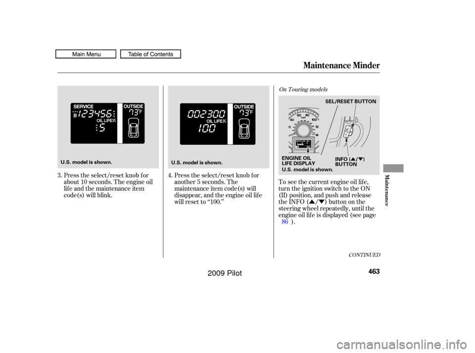
Press the select/reset knob f or
about 10 seconds. The engine oil
lif e and the maintenance item
code(s) will blink.Press the select/reset knob f or
another 5 seconds. The
maintenance item code(s) will
disappear, and the engine oil lif e
will reset to ‘‘100.’’To see the current engine oil lif e,
turn the ignition switch to the ON
(II) position, and push and release
the INFO ( / ) button on the
steering wheel repeatedly, until the
engine oil lif e is displayed (see page
).
3.
4.
86
CONT INUED
On Touring models
Maintenance Minder
Maint enance
463
ENGINE OIL
LIFE DISPLAYSEL/RESET BUTTON
INFO ( / )
BUTTON
U.S. model is shown.
U.S. model is shown.
U.S. model is shown.
�����—�����—�
���y�
���������
���y���
�(�/���������y���������y
2009 Pilot
Page 473 of 578

Press and hold the SEL/RESET
button on the steering wheel f or
more than 10 seconds. The
remaining engine oil lif e reset
mode will be shown on the multi-
inf ormation display.
All maintenance items displayed on
the inf ormation display are in code.
For an explanation of these
maintenance codes, see page . Your dealer will reset the display
af ter completing the required
maintenance service. You will see
‘‘OIL LIFE 100%’’ on the display the
next time you turn the ignition
switch to the ON (II) position.
If maintenance service is done by
someone other than your dealer,
reset the maintenance minder as
f ollows:
Turn the ignition switch to the ON
(II) position.
Press the SEL/RESET button on
the steering wheel until you see
the engine oil lif e display.
1.
2. 3.
473
CONT INUED
On Touring models On Touring models
Maintenance Main Items and Sub
ItemsResetting the Engine Oil Lif e
Display
Maintenance Minder
Maint enance
469
MAINTENANCE
MAIN ITEMMAINTENANCE
SUB ITEM(S)
U.S. model is shown.
�����—�����—�
���y�
�������������y���
�(�/���������y���������y
2009 Pilot
Page 474 of 578
 button, then press
the SEL/RESET button to reset
the engine oil lif e display. The
maintenance item code(s) will
disappear, and the engine oi")
�Û�Ý
Select ‘‘RESET’’ by pressing the
INFO ( / ) button, then press
the SEL/RESET button to reset
the engine oil lif e display. The
maintenance item code(s) will
disappear, and the engine oil lif e
will reset to ‘‘100.’’ If you want to
cancel the oil lif e reset mode,
select ‘‘CANCEL.’’ Your authorized dealer knows your
vehicle best and can provide
competent, ef f icient service.
However, service at a dealer is not
mandatory to keep your warranties
in effect. Maintenance may be done
by any qualif ied service f acility or
person who is skilled in this type of
automotive service. Keep all receipts
as proof of completion, and have the
person who does the work f ill out
your Maintenance Journal or
Canadian Maintenance Log. Check
your warranty booklet f or more
inf ormation.
If you have the required service
done but do not reset the display, or
reset the display without doing the
service, the system will not show the
proper maintenance intervals. This
canleadtoseriousmechanical
problems because you will no longer
have an accurate record of when
maintenance is needed.
4.
Maintenance Minder
Important Maintenance
Precautions
470
U.S. model is shown.
�����—�����—�
���y�
������
������y���
�(�/���������y���������y
2009 Pilot
Page 486 of 578
Remove the dipstick (yellow loop)
f rom the transmission, and wipe it
with a clean cloth.Insert the dipstick all the way into
the transmission securely as
shown in the illustration.
Remove the dipstick and check
the f luid level. It should be
between the upper and lower
marks.
Check the f luid level with the engine
at normal operating temperature.
Park the vehicle on level ground.
Start the engine, let it run until the
radiator f an comes on, then shut
of f the engine. For accurate
results, wait about 60 seconds (but
no longer than 90 seconds) bef ore
doing step 2.
The transmission should be drained
and ref illed with new f luid when this
service is shown on the inf ormation
display or multi-inf ormation display
(depending on models).
1.
2.3.
4.
Automatic Transmission Fluid
482
DIPSTICKDIPSTICK
UPPER MARK
LOWER MARK
�����—�����—�
���y�
�������������y���
�(�/���������y���������y
2009 Pilot


f rom the transmission, and wipe it
with a clean cloth.Insert the dipstick all the way into
the transmission securely as
shown in the illustration.
Remove the dipstic")