2009 FIAT PANDA batter
[x] Cancel search: batterPage 10 of 226

9KNOW YOUR
VEHICLESAFETY
CORRECT USE
OF THE CAR
WARNING LIGHTS
AND MESSAGES
IN
AN EMERGENCY
CAR
MAINTENANCE
TECHNICAL
SPECIFICATIONS
INDEX
F0Z0683m
fig. 8
F0Z0684m
fig. 9
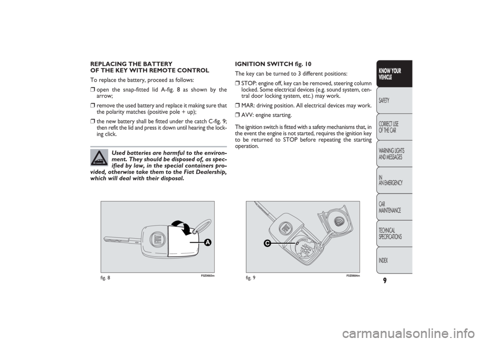
REPLACING THE BATTERY
OF THE KEY WITH REMOTE CONTROL
To replace the battery, proceed as follows:❒
open the snap-fitted lid A-fig. 8 as shown by the
arrow;
❒
remove the used battery and replace it making sure that
the polarity matches (positive pole + up);
❒
the new battery shall be fitted under the catch C-fig. 9;
then refit the lid and press it down until hearing the lock-
ing click.IGNITION SWITCH fig. 10
The key can be turned to 3 different positions:
❒
STOP: engine off, key can be removed, steering column
locked. Some electrical devices (e.g. sound system, cen-
tral door locking system, etc.) may work.
❒
MAR: driving position. All electrical devices may work.
❒
AVV: engine starting.
The ignition switch is fitted with a safety mechanisms that, in
the event the engine is not started, requires the ignition key
to be returned to STOP before repeating the starting
operation.
Used batteries are harmful to the environ-
ment. They should be disposed of, as spec-
ified by law, in the special containers pro-
vided, otherwise take them to the Fiat Dealership,
which will deal with their disposal.
001-030 PANDA EN 7-10-2009 13:39 Pagina 9
Page 15 of 226

14
KNOW YOUR
VEHICLE
SAFETY
CORRECT USE
OF THE CAR
WARNING LIGHTS
AND MESSAGES
IN
AN EMERGENCY
CAR
MAINTENANCE
TECHNICAL
SPECIFICATIONS
INDEX
F0Z0146m
fig. 17
F0Z0256m
fig. 18
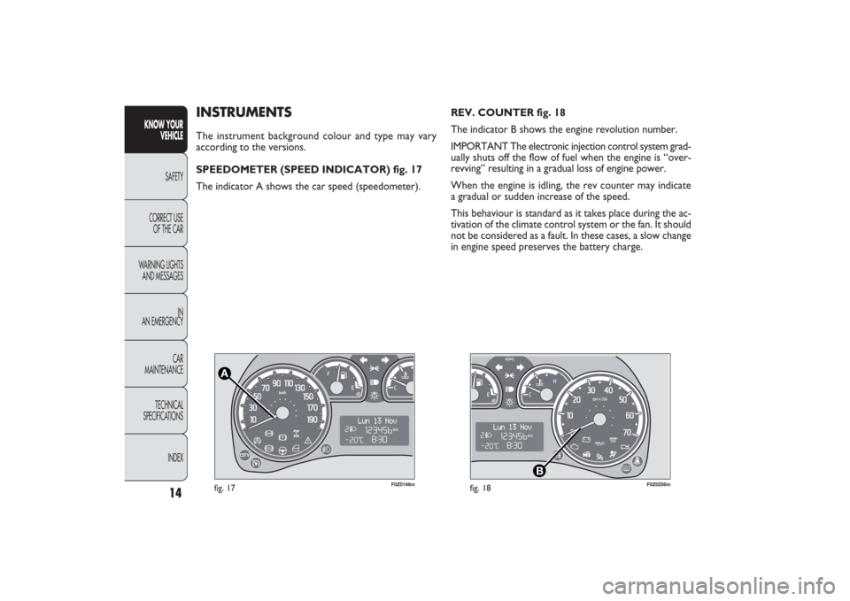
REV. COUNTER fig. 18
The indicator B shows the engine revolution number.
IMPORTANT The electronic injection control system grad-
ually shuts off the flow of fuel when the engine is “over-
revving” resulting in a gradual loss of engine power.
When the engine is idling, the rev counter may indicate
a gradual or sudden increase of the speed.
This behaviour is standard as it takes place during the ac-
tivation of the climate control system or the fan. It should
not be considered as a fault. In these cases, a slow change
in engine speed preserves the battery charge.
INSTRUMENTSThe instrument background colour and type may vary
according to the versions.
SPEEDOMETER (SPEED INDICATOR) fig. 17
The indicator A shows the car speed (speedometer).
001-030 PANDA EN 7-10-2009 13:39 Pagina 14
Page 30 of 226

29KNOW YOUR
VEHICLESAFETY
CORRECT USE
OF THE CAR
WARNING LIGHTS
AND MESSAGES
IN
AN EMERGENCY
CAR
MAINTENANCE
TECHNICAL
SPECIFICATIONS
INDEX
New mission
A new mission starts after:
– “manual” resetting by the user, by pressing the relevant
button;
– “automatic” resetting, when the “Trip distance” reaches
3999.9 km or 9999.9 km (according to the type of display)
or when the “Trip time” reaches 99.59 (99 hours and 59
minutes);
– disconnection/reconnection of the battery.
IMPORTANT The reset operations performed after the
“General Trip” message displaying are used to also reset
the “Trip B”, which, on its turn, is used to reset the
values of the corresponding function. Average speed
This shows the car average speed as a function of the over-
all time elapsed since the start of the new mission.
Trip time
This value shows the time elapsed since the start of the
new mission.
IMPORTANT Lacking information, Trip Computer values
are displayed with “----”. When normal operating condi-
tion is reset, calculation of different units will restart reg-
ularly. All values displayed before the failure will not be
reset nor a new mission is started.
Button TRIP fig. 29
The button
TRIP
is located on the top of the right-hand
lever. With the ignition key turned to
MAR
, by this but-
ton the previously described parameters can be displayed
and reset to start a new mission:
– short pressing to display the different values;
– prolonged pressing to reset and then start a new
mission.
TRIP
F0Z0149m
fig. 29
001-030 PANDA EN 7-10-2009 13:40 Pagina 29
Page 53 of 226

F0Z0032m
fig. 51
Ceiling light timing (lens central position)
Three different switching-on modes are provided:❒
when opening one door a three-minute timing will start,
to be repeated each time one door is opened;
❒
approximately 10-second timing will start when re-
moving the ignition key within two minutes from turn-
ing the engine off;
❒
approximately 10-second timing will start when open-
ing the doors (by both remote control or key into
driver’s door lock).
Two switching-off modes are provided:
❒
when closing all doors, the 3-minute timing will go
off and a 10-second one will start. This timing will
go off when turning the key to MAR;
❒
when locking the doors (by both remote control or key
into driver’s door lock), the ceiling light goes off.
On Emotion and Dynamic versions, the ceiling light will
switch on and off gradually; the ceiling light will switch off
automatically 15 minutes after turning the engine off.
CEILING LIGHTFRONT CEILING LIGHT fig. 51
The lens A can have three positions:❒
side
a
pressed: light always on
❒
side
b
pressed: light always off
❒
central position (neutral): the light turns on and off when
the doors are opened or closed.
IMPORTANT Before getting out of the car, make sure the
switch is at central position: ensure that lights are off with
doors closed to avoid draining the battery.
For “Active” versions, lights switching-on and off occur
only when the front driver’s door is opened or closed.
52
KNOW YOUR
VEHICLE
SAFETY
CORRECT USE
OF THE CAR
WARNING LIGHTS
AND MESSAGES
IN
AN EMERGENCY
CAR
MAINTENANCE
TECHNICAL
SPECIFICATIONS
INDEX
031-064 PANDA EN 7-10-2009 13:43 Pagina 52
Page 56 of 226

55KNOW YOUR
VEHICLESAFETY
CORRECT USE
OF THE CAR
WARNING LIGHTS
AND MESSAGES
IN
AN EMERGENCY
CAR
MAINTENANCE
TECHNICAL
SPECIFICATIONS
INDEX
F0Z0223m
fig. 55
Carefully inspect the car for fuel leakages, e.g. in the en-
gine compartment, under the car or near the fuel tank.
If no fuel leaks are found and the car can be started again,
press the button A to reset the fuel system and the lights.
After a collision, turn the ignition key to STOP to pre-
vent battery running down.
If, after a collision, you smell fuel or see
leaks from the fuel system, do not reset the
switches to avoid fire risk.
WARNING
INTERIOR FITTINGSCIGAR LIGHTER AND ASHTRAY fig. 55
(for versions/markets where provided)
Press the button A; after about 15 seconds it will return
to its original position and the cigar lighter is ready for use.
IMPORTANT Always check that the cigar lighter has
turned off.
The cigar lighter gets very hot. Handle it
carefully and make sure children don’t
touch it: risk of fire and/or burns.
WARNING
031-064 PANDA EN 7-10-2009 13:43 Pagina 55
Page 59 of 226

F0Z0130m
fig. 61
F0Z0198m
fig. 62
CURRENT SOCKET fig. 61
(for versions/markets where provided)
The current socked is located on the central tunnel
and is powered with ignition key on MAR.
To use the socket, open the protection lid A.
Correct operation is ensured only if the connected ac-
cessories are provided with approved standard plugs, pre-
sent on all Lineaccessori Fiat components.
IMPORTANT With the engine off and ignition key in MAR,
the extended use (for instance for over one hour) of ac-
cessories which drain much current may reduce battery
efficiency and therefore cause misfiring.
58
KNOW YOUR
VEHICLE
SAFETY
CORRECT USE
OF THE CAR
WARNING LIGHTS
AND MESSAGES
IN
AN EMERGENCY
CAR
MAINTENANCE
TECHNICAL
SPECIFICATIONS
INDEX
Only accessories with a maximum power of
180 W (maximum absorption 15 A) can be
connected to the socket.
POWER SUN-ROOF (SKY-DOME)Upon request, the car can be fitted a power sun-roof con-
sisting of two glass panels fig. 62 and sun curtains fig. 63:
A front mobile pane;
B rear fixed pane;
D sun curtains (two): to open, make the curtain slide as
shown by the arrow.
031-064 PANDA EN 7-10-2009 13:43 Pagina 58
Page 85 of 226

F0Z0071m
fig. 94
SOUND SYSTEMWhen the sound system has not been requested, the car
is provided with two oddment compartments on the
instrument panel.
STANDARD EQUIPMENT fig. 94
The system consists of:❒
sound system power wires;
❒
sound system compartment;
❒
housings for front and rear speakers in the doors.
Remove door panels to install the speakers. Have this
operation carried out at a Fiat Dealership.
The sound system must be fitted in the dedicated seat
inside the oddment compartment, which can beremoved
by pressing the two retaining tabs A. Here, you can find
the power supply wires.SOUND SYSTEM PRESETTING
(for versions/markets where provided)
In addition to the standard equipment the car also features:
❒
two 165 mm full range 40 W speakers in the front
doors;
❒
two 130 mm full range 350 W speakers in the rear
doors;
❒
aerial power cable;
❒
front and rear speaker power wires;
❒
sound system power wires;
❒
aerial on the car roof.
If you wish to have a sound system installed
after purchasing the car, first contact
a Fiat Dealership whose qualified person-
nel will give you advise about a sound system that
does not damage the battery charge. Excessive ab-
sorption will drain and damage the battery and may
invalidate the battery warranty.
84
KNOW YOUR
VEHICLE
SAFETY
CORRECT USE
OF THE CAR
WARNING LIGHTS
AND MESSAGES
IN
AN EMERGENCY
CAR
MAINTENANCE
TECHNICAL
SPECIFICATIONS
INDEX
065-090 PANDA EN 7-10-2009 13:45 Pagina 84
Page 87 of 226

INSTALLATION OF ELECTRICAL/
ELECTRONIC DEVICES
Electrical and electronic devices installed after buying
the vehicle and available as after-sales must carry the
following label:
Fiat Auto S.p.A. authorises the installation of transceivers
provided that installation is carried out at a specialised
shop, workmanlike performed and in compliance with
manufacturer’s specifications.
IMPORTANT Installation of devices resulting in modifi-
cations of vehicle characteristics may cause driving license
seizing by traffic control authorities and also the lapse of
the warranty for defects due to the above-mentioned mod-
ification or either directly or indirectly related to it.
Fiat Auto S.p.A. shall not be liable for damage caused
by the installation of accessories either not supplied or rec-
ommended by Fiat Auto S.p.A. and/or not installed in com-
pliance with the provided instructions. ACCESSORIES PURCHASED BY THE OWNER
If after buying the car, you decide to install electrical ac-
cessories that require a steady electric supply (alarm, satel-
lite antitheft system, etc.) or accessories that in any case
burden the electric supply, contact Fiat Dealership, whose
qualified personnel, besides suggesting the most suitable
devices belonging to Lineaccessori Fiat, will also evaluate
the overall electric consumption, checking whether
the car’s electric system is able to withstand the load
required, or whether it needs to be integrated with a more
powerful battery.
86
KNOW YOUR
VEHICLE
SAFETY
CORRECT USE
OF THE CAR
WARNING LIGHTS
AND MESSAGES
IN
AN EMERGENCY
CAR
MAINTENANCE
TECHNICAL
SPECIFICATIONS
INDEX
065-090 PANDA EN 7-10-2009 13:45 Pagina 86