2009 FIAT PANDA Sound
[x] Cancel search: SoundPage 4 of 226

3KNOW YOUR
VEHICLESAFETY
CORRECT USE
OF THE CAR
WARNING LIGHTS
AND MESSAGES
IN
AN EMERGENCY
CAR
MAINTENANCE
TECHNICAL
SPECIFICATIONS
INDEX
KNOW YOUR VEHICLE
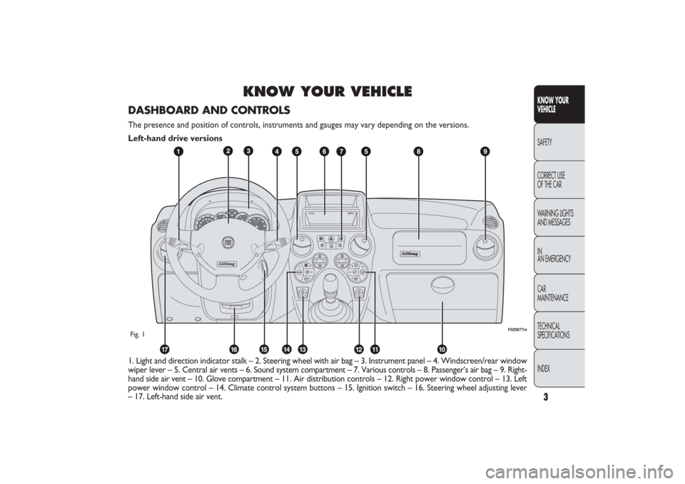
1. Light and direction indicator stalk – 2. Steering wheel with air bag – 3. Instrument panel – 4. Windscreen/rear window
wiper lever – 5. Central air vents – 6. Sound system compartment – 7. Various controls – 8. Passenger’s air bag – 9. Right-
hand side air vent – 10. Glove compartment – 11. Air distribution controls – 12. Right power window control – 13. Left
power window control – 14. Climate control system buttons – 15. Ignition switch – 16. Steering wheel adjusting lever
– 17. Left-hand side air vent.
F0Z0677m
Fig. 1DASHBOARD AND CONTROLSThe presence and position of controls, instruments and gauges may vary depending on the versions.
Left-hand drive versions
001-030 PANDA EN 7-10-2009 13:39 Pagina 3
Page 5 of 226

4
KNOW YOUR
VEHICLE
SAFETY
CORRECT USE
OF THE CAR
WARNING LIGHTS
AND MESSAGES
IN
AN EMERGENCY
CAR
MAINTENANCE
TECHNICAL
SPECIFICATIONS
INDEX
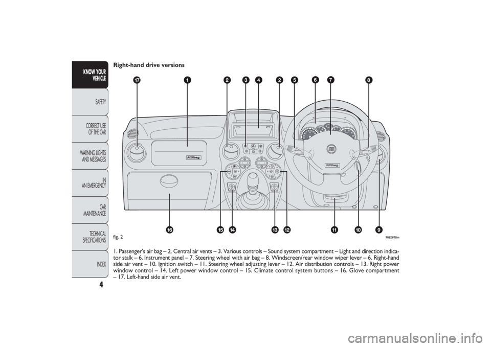
Right-hand drive versions
1. Passenger’s air bag – 2. Central air vents – 3. Various controls – Sound system compartment – Light and direction indica-
tor stalk – 6. Instrument panel – 7. Steering wheel with air bag – 8. Windscreen/rear window wiper lever – 6. Right-hand
side air vent – 10. Ignition switch – 11. Steering wheel adjusting lever – 12. Air distribution controls – 13. Right power
window control – 14. Left power window control – 15. Climate control system buttons – 16. Glove compartment
– 17. Left-hand side air vent.
CH
F
E
F0Z0678m
fig. 2
001-030 PANDA EN 7-10-2009 13:39 Pagina 4
Page 10 of 226

9KNOW YOUR
VEHICLESAFETY
CORRECT USE
OF THE CAR
WARNING LIGHTS
AND MESSAGES
IN
AN EMERGENCY
CAR
MAINTENANCE
TECHNICAL
SPECIFICATIONS
INDEX
F0Z0683m
fig. 8
F0Z0684m
fig. 9
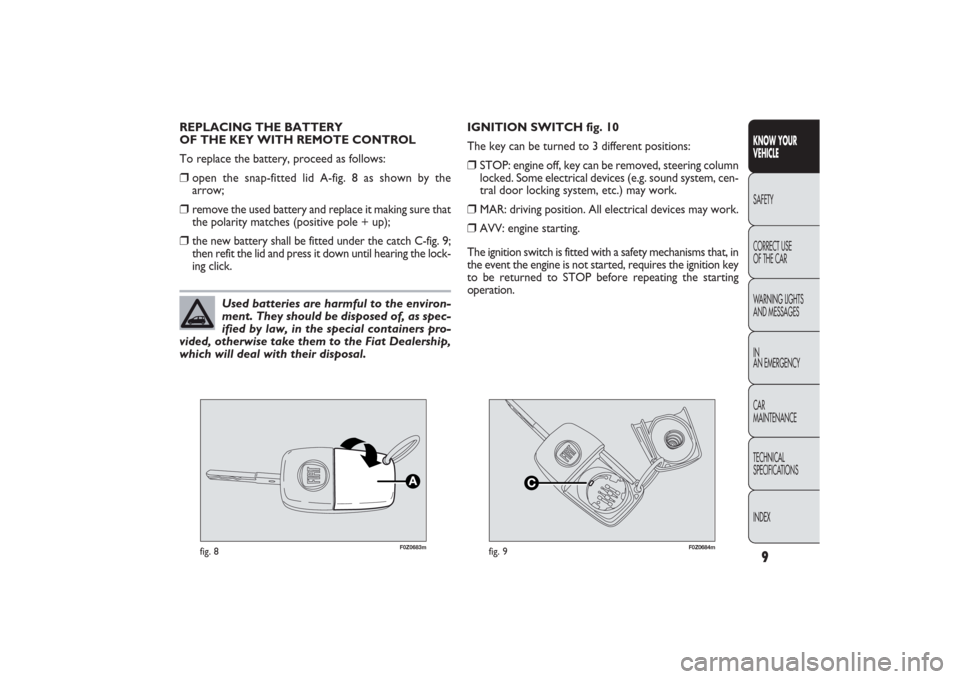
REPLACING THE BATTERY
OF THE KEY WITH REMOTE CONTROL
To replace the battery, proceed as follows:❒
open the snap-fitted lid A-fig. 8 as shown by the
arrow;
❒
remove the used battery and replace it making sure that
the polarity matches (positive pole + up);
❒
the new battery shall be fitted under the catch C-fig. 9;
then refit the lid and press it down until hearing the lock-
ing click.IGNITION SWITCH fig. 10
The key can be turned to 3 different positions:
❒
STOP: engine off, key can be removed, steering column
locked. Some electrical devices (e.g. sound system, cen-
tral door locking system, etc.) may work.
❒
MAR: driving position. All electrical devices may work.
❒
AVV: engine starting.
The ignition switch is fitted with a safety mechanisms that, in
the event the engine is not started, requires the ignition key
to be returned to STOP before repeating the starting
operation.
Used batteries are harmful to the environ-
ment. They should be disposed of, as spec-
ified by law, in the special containers pro-
vided, otherwise take them to the Fiat Dealership,
which will deal with their disposal.
001-030 PANDA EN 7-10-2009 13:39 Pagina 9
Page 21 of 226

20
KNOW YOUR
VEHICLE
SAFETY
CORRECT USE
OF THE CAR
WARNING LIGHTS
AND MESSAGES
IN
AN EMERGENCY
CAR
MAINTENANCE
TECHNICAL
SPECIFICATIONS
INDEX
Selecting an option from the main menu without submenu:
– briefly press the button MODE to select the main menu
option to be changed;
– press buttons + or − (with a single press) to select the
new setting;
– briefly press the button MODE to store the new set-
ting and at the same time go back to the previously se-
lected main menu option.
Selecting of an option from the main menu with submenu:
– briefly press the button MODE to display the first sub-
menu option;
– press buttons + or − (with a single press) to scroll
through all submenu options;
– briefly press the buttonMODE to select the displayed
submenu option and to open the relevant set-up menu;
– press buttons + or − (with a single press) to choose a
new setting for this submenu option;
– briefly press the button MODE to store the new set-
ting and at the same time go back to the previously se-
lected submenu option. Passenger compartment light adjustment
– to adjust instrument panel, sound system and automat-
ic climate control system display brightness when the stan-
dard screen is active.
Setup menu
– within the menu, they allow you to scroll up and down
through the options;
– during setting operations they increase or decrease
the values.
SETUP MENU fig. 28
The menu comprises a series of functions arranged in a cy-
cle which can be selected through buttons
+and
−to ac-
cess the different select operations and settings (setup)
given in the following paragraphs.
A submenu is provided for some items (Setting the clock
and Set units).
The setup menu is activated by pressing briefly the but-
ton MODE.
Single presses on buttons + or − will scroll the setup menu
options.
Operating modes are different according to the charac-
teristic of the option selected.
001-030 PANDA EN 7-10-2009 13:39 Pagina 20
Page 26 of 226

25KNOW YOUR
VEHICLESAFETY
CORRECT USE
OF THE CAR
WARNING LIGHTS
AND MESSAGES
IN
AN EMERGENCY
CAR
MAINTENANCE
TECHNICAL
SPECIFICATIONS
INDEX
– briefly press the MODE button: “On” or “Off” will flash
on the display (depending on the previous setting);
– press the button + or − to select;
– briefly press the button MODE to go back to the sub-
menu screen or press the button for a prolonged time to
go back to the standard screen without storing settings;
– press the button MODE again for a longer time to go
back to the standard screen or to the main menu according
to the current menu level displayed.
Set units (Measurement units)
With this function it is possible to set the units through three
submenus: “Distances”, “Consumption” and “Temperature”.
To set the required unit proceed as follows:
– briefly press the button MODE to display the three
submenus;
– press the button + or − to switch between the three
submenus;
– once you have selected the submenu to be changed, press
the MODE button briefly;
– when accessing the “Distance” submenu:and briefly press the
button MODE and the display will show “km” or “mi”
(depending on the previous setting);
– press the button + or − to select; Audio repetition (See radio)
With this function the display shows information about the
sound system.
– Radio: selected radio station frequency or RDS message,
automatic tuning activation or AutoSTore;
– Audio CD, MP3 CD: track number;
– CD Changer: CD number and track number;
– Tape: operating mode.
To show the sound system information on the display (On)
or clear it (Off), proceed as follows:
– briefly press the button MODE: (On) or (Off) will flash
on the display (depending on the previous setting);
– press the button + or − to select;
– briefly press the button MODE to go back to the menu
screen or press the button for a prolonged time to go back
to the standard screen without storing the settings.
Automatic central door locking
with car running
(Autoclose)
When activated (On), this function locks automatically the
doors when the vehicle speed exceeds 20 km/h.
Proceed as follows to activate (On) or deactivate (Off) this
function:
– briefly press the button MODE to display one submenu;
001-030 PANDA EN 7-10-2009 13:40 Pagina 25
Page 84 of 226

GENERAL WARNINGS❒
When parking, take the utmost care to obstacles that
may be set above or under the sensors.
❒
Objects set close to the car rear, under certain cir-
cumstances are not detected and could therefore cause
damage to the car or be damaged.
❒
Indications sent by the sensors can be altered by dirt,
snow or ice deposited on the sensors or by ultrasound
systems (e.g.: truck pneumatic brakes or pneumatic
hammers) set nearby the car.
For proper operation, sensors must always
be clean from mud, dirt, snow or ice.
Be careful not to scratch or damage the
sensors while cleaning them. Avoid using dry, rough
or hard cloths. The sensors should be washed us-
ing clean water with the addition of car shampoo
if necessary. When using special washing equipment
such as high pressure jets or steam cleaning, clean
the sensors very quickly keeping the jet more than
10 cm away.
Parking manoeuvres however are always
under the driver’s responsibility. While ma-
noeuvring, the driver shall always make sure that
no-one is standing in the area, especially children
or animals. The parking sensor is designed to as-
sist drivers, who shall never reduce attention dur-
ing potentially dangerous manoeuvres even if per-
formed at low speed.
WARNING
83KNOW YOUR
VEHICLESAFETY
CORRECT USE
OF THE CAR
WARNING LIGHTS
AND MESSAGES
IN
AN EMERGENCY
CAR
MAINTENANCE
TECHNICAL
SPECIFICATIONS
INDEX
065-090 PANDA EN 7-10-2009 13:45 Pagina 83
Page 85 of 226

F0Z0071m
fig. 94
SOUND SYSTEMWhen the sound system has not been requested, the car
is provided with two oddment compartments on the
instrument panel.
STANDARD EQUIPMENT fig. 94
The system consists of:❒
sound system power wires;
❒
sound system compartment;
❒
housings for front and rear speakers in the doors.
Remove door panels to install the speakers. Have this
operation carried out at a Fiat Dealership.
The sound system must be fitted in the dedicated seat
inside the oddment compartment, which can beremoved
by pressing the two retaining tabs A. Here, you can find
the power supply wires.SOUND SYSTEM PRESETTING
(for versions/markets where provided)
In addition to the standard equipment the car also features:
❒
two 165 mm full range 40 W speakers in the front
doors;
❒
two 130 mm full range 350 W speakers in the rear
doors;
❒
aerial power cable;
❒
front and rear speaker power wires;
❒
sound system power wires;
❒
aerial on the car roof.
If you wish to have a sound system installed
after purchasing the car, first contact
a Fiat Dealership whose qualified person-
nel will give you advise about a sound system that
does not damage the battery charge. Excessive ab-
sorption will drain and damage the battery and may
invalidate the battery warranty.
84
KNOW YOUR
VEHICLE
SAFETY
CORRECT USE
OF THE CAR
WARNING LIGHTS
AND MESSAGES
IN
AN EMERGENCY
CAR
MAINTENANCE
TECHNICAL
SPECIFICATIONS
INDEX
065-090 PANDA EN 7-10-2009 13:45 Pagina 84
Page 86 of 226

F0Z0073m
fig. 95
With HiFi system (if requested):❒
two tweeters A – fig. 95 and two woofers B, 40 W max.
power each, on the front doors;
❒
two full range 40 W speakers, in the rear doors;
❒
a 100 W subwoofer under the right seat;
❒
aerial on the roof;
❒
sound system with CD player or sound system with CD
MP3 player (for its operation and characteristics see the
“Sound system” supplement attached to the present
Handbook). SOUND SYSTEM (for versions/markets, where
provided)
The complete system consists of:
❒
two 165 mm full range 40 W speakers in the front
doors;
❒
two 130 mm full range 350 W speakers in the rear
doors;
❒
aerial on the car roof;
❒
radio with tape-recorder or sound system with CD
player or sound system with MP3 CD player (for its op-
eration and characteristics see the “Sound system” sup-
plement attached to the present Handbook).
85KNOW YOUR
VEHICLESAFETY
CORRECT USE
OF THE CAR
WARNING LIGHTS
AND MESSAGES
IN
AN EMERGENCY
CAR
MAINTENANCE
TECHNICAL
SPECIFICATIONS
INDEX
065-090 PANDA EN 7-10-2009 13:45 Pagina 85