Page 375 of 532

Tire Pressure Monitoring Low Pressure Warnings
The “Tire Pressure Monitoring Telltale Light” will
illuminate in the instrument cluster, and an au-
dible chime will be activated when one or more of
the four active road tire pressures are low. Should this
occur, you should stop as soon as possible, check the
inflation pressure of each tire on your vehicle and inflate
each tire to the vehicle’s recommended cold placard
pressure value. The system will automatically update
and the “Tire Pressure Monitoring Telltale Light” will
extinguish once the updated tire pressures have been
received. The vehicle may need to be driven for up to
20 minutes above 15 mph (25 km/h) to receive this
information.
Check TPMS WarningsThe “Tire Pressure Monitoring Telltale Light” (located in
the instrument cluster) will flash on and off for 75 sec-
onds and will remain on solid when a system fault is
detected. The system fault will also sound a chime. If the ignition key is cycled, this sequence will repeat, provid-
ing the system fault still exists. A system fault can occur
by any of the following scenarios:
1. Signal interference due to electronic devices or driving
next to facilities emitting the same Radio Frequencies as
the TPM sensors.
2. Installing aftermarket window tinting that affects ra-
dio wave signals.
3. Accumulation of snow or ice around the wheels or
wheel housings.
4. Using tire chains on the vehicle.
5. Using wheels/tires not equipped with TPM sensors.
6. Loss of communication with the trigger modules or
tire pressure monitoring sensors.
NOTE: Your vehicle is equipped with a non-matching
full size spare wheel and tire assembly.
STARTING AND OPERATING 373
5
Page 384 of 532

Gross Axle Weight Rating (GAWR)The GAWR is the maximum permissible load on the front
and rear axles. The load must be distributed in the cargo
area so that the GAWR of each axle is not exceeded.
Each axle GAWR is determined by the components in the
system with the lowest load carrying capacity (axle,
springs, tires or wheels). Heavier axles or suspension
components sometimes specified by purchasers for in-
creased durability does not necessarily increase the vehi-
cle’s GVWR.Tire SizeThe tire size on the Label represents the actual tire size on
your vehicle. Replacement tires must be equal to the load
capacity of this tire size.Rim SizeThis is the rim size that is appropriate for the tire size
listed.
Inflation PressureThis is the cold tire inflation pressure for your vehicle for
all loading conditions up to full GAWR.Curb WeightThe curb weight of a vehicle is defined as the total weight
of the vehicle with all fluids, including vehicle fuel, at full
capacity conditions, and with no occupants or cargo
loaded into the vehicle. The front and rear curb weight
values are determined by weighing your vehicle on a
commercial scale before any occupants or cargo are
added.LoadingThe actual total weight and the weight of the front and
rear of your vehicle at the ground can best be determined
by weighing it when it is loaded and ready for operation.
The entire vehicle should first be weighed on a commer-
cial scale to insure that the GVWR has not been exceeded.
The weight on the front and rear of the vehicle should
382 STARTING AND OPERATING
Page 394 of 532

4. Tongue weight rating for the trailer hitch utilized
(This requirement may limit the ability to always
achieve the 10% to 15% range of tongue weight as a
percentage of total trailer weight).Towing Requirements — Tires
�
Do not attempt to tow a trailer while using a compact
spare tire.
�
Proper tire inflation pressures are essential to the safe
and satisfactory operation of your vehicle. Refer to
“Tires–General Information” for proper tire inflation
procedures.
�
Check the trailer tires for proper tire inflation pres-
sures before trailer usage.
�
Check for signs of tire wear or visible tire damage
before towing a trailer. Refer to “Tires–General Infor-
mation” for the proper inspection procedure.
�
When replacing tires, refer to “Tires–General Informa-
tion” for proper tire replacement procedures. Replac-
ing tires with a higher load carrying capacity will not
increase the vehicle’s GVWR and GAWR limits.
Towing Requirements — Trailer Brakes
�
Do not interconnect the hydraulic brake system or
vacuum system of your vehicle with that of the trailer.
This could cause inadequate braking and possible
personal injury.
�
An electronically actuated trailer brake controller is
required when towing a trailer with electronically
actuated brakes. When towing a trailer equipped with
a hydraulic surge actuated brake system, an electronic
brake controller is not required.
�
Trailer brakes are recommended for trailers over
1,000 lbs (454 kg) and required for trailers in excess of
2,000 lbs (907 kg).
392 STARTING AND OPERATING
Page 410 of 532
Removing The Spare TireRemove the spare tire before attempting to jack the truck.
Attach the wheel wrench to the jack extension tube. Insert
the tube through the access hole between the lower
tailgate and the top of the bumper and into the winch
mechanism tube. Rotate the wheel wrench handle coun-
terclockwise until the spare tire is on the ground with
enough cable slack to allow you to pull it out from under
the vehicle. When the spare is clear, tilt the retainer at the
end of the cable and pull it through the center of the
wheel.
NOTE:Always stow the spare tire with the valve stem
facing the ground.
It is recommended that you stow the flat or spare to
avoid tangling the loose cable.
Removing the Spare Tire
1 — Lower
2 — Raise
408 WHAT TO DO IN EMERGENCIES
Page 413 of 532
WARNING! (Continued)
•
Do not get under the vehicle when it is on a jack.
•
Only use the jack in the positions indicated and
for lifting this vehicle during a tire change.
•
If working on or near a roadway, be extremely
careful of motor traffic.
•
To assure that spare tires, flat or inflated, are
securely stowed, spares must be stowed with the
valve stem facing the ground.
•
Turn on the Hazard Warning flasher.
1. Remove the spare wheel, jack, and tools from storage. 2. Using the wheel wrench, loosen, but do not remove,
the wheel nuts by turning them counterclockwise one
turn while the wheel is still on the ground.
3. Placement of the Jack:
•
For 2500/3500 4x2 series trucks, when changing a
front wheel, place the bottle jack under the frame
rail behind the wheel. Locate the jack as far forward
as possible on the straight part of the frame.
Jack Warning Label
4x2 Jacking Location
WHAT TO DO IN EMERGENCIES 411
6
Page 415 of 532

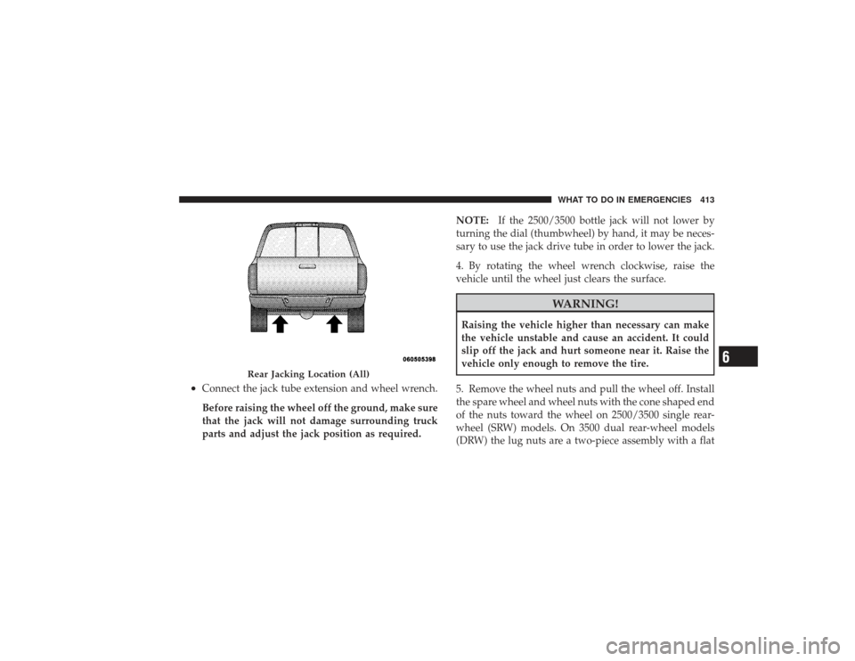
•
Connect the jack tube extension and wheel wrench.
Before raising the wheel off the ground, make sure
that the jack will not damage surrounding truck
parts and adjust the jack position as required.NOTE:
If the 2500/3500 bottle jack will not lower by
turning the dial (thumbwheel) by hand, it may be neces-
sary to use the jack drive tube in order to lower the jack.
4. By rotating the wheel wrench clockwise, raise the
vehicle until the wheel just clears the surface.
WARNING!
Raising the vehicle higher than necessary can make
the vehicle unstable and cause an accident. It could
slip off the jack and hurt someone near it. Raise the
vehicle only enough to remove the tire.
5. Remove the wheel nuts and pull the wheel off. Install
the spare wheel and wheel nuts with the cone shaped end
of the nuts toward the wheel on 2500/3500 single rear-
wheel (SRW) models. On 3500 dual rear-wheel models
(DRW) the lug nuts are a two-piece assembly with a flat
Rear Jacking Location (All)
WHAT TO DO IN EMERGENCIES 413
6
Page 417 of 532

Insert the blade end into the pry-off notch and carefully
pop off the hub cap with a back-and-forth motion.
On 3500 models with dual rear wheels (DRW), you must
first remove the hub caps. The jack handle driver has a
hook at one end that will fit in the pry off notch of the
rear hub caps. Position the hook and pull out on the
ratchet firmly. The hub cap should pop off. The wheel
skins can now be removed. For the front hub cap on 3500
models use the blade on the end of the lug wrench to pry
the caps off. The wheel skin can now be removed.
CAUTION!
•
Use a back-and-forth motion to remove the hub
cap. Do not use a twisting motion when removing
the hub cap, damage to the hub cap finish may
occur.(Continued)
CAUTION! (Continued)
•
The rear hub caps on the dual rear wheel has two
pry-off notches. Make sure that the hook of the
jack handle driver is located squarely in the cap
notch before attempting to pull off.
You must use the flat end of the lug wrench to pry off the
wheel skins. Insert the flat tip completely and using a
back-and-forth motion, loosen the wheel skin. Repeat this
procedure around the tire until the skin pops off.
Replace the wheel skins first using a rubber mallet. When
replacing the hub caps, tilt the cap retainer over the
lugnut bolt circle and strike the high side down with a
rubber mallet. Be sure that the hub caps and wheel skins
are firmly seated around the wheel.
WHAT TO DO IN EMERGENCIES 415
6
Page 418 of 532

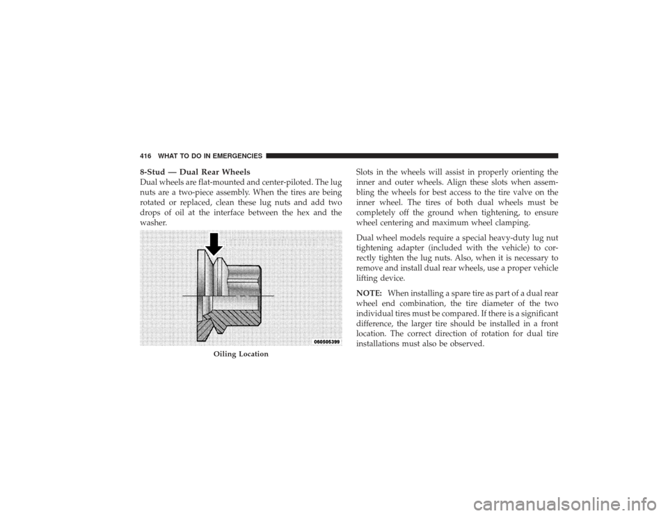
8-Stud — Dual Rear WheelsDual wheels are flat-mounted and center-piloted. The lug
nuts are a two-piece assembly. When the tires are being
rotated or replaced, clean these lug nuts and add two
drops of oil at the interface between the hex and the
washer.Slots in the wheels will assist in properly orienting the
inner and outer wheels. Align these slots when assem-
bling the wheels for best access to the tire valve on the
inner wheel. The tires of both dual wheels must be
completely off the ground when tightening, to ensure
wheel centering and maximum wheel clamping.
Dual wheel models require a special heavy-duty lug nut
tightening adapter (included with the vehicle) to cor-
rectly tighten the lug nuts. Also, when it is necessary to
remove and install dual rear wheels, use a proper vehicle
lifting device.
NOTE:
When installing a spare tire as part of a dual rear
wheel end combination, the tire diameter of the two
individual tires must be compared. If there is a significant
difference, the larger tire should be installed in a front
location. The correct direction of rotation for dual tire
installations must also be observed.
Oiling Location
416 WHAT TO DO IN EMERGENCIES