2009 DODGE DAKOTA ignition
[x] Cancel search: ignitionPage 146 of 449
WARNING!
Vehicle exhaust contains carbon monoxide, a danger-
ous gas. Do not run your vehicle in the garage while
training the transceiver. Exhaust gas can cause seri-
ous injury or death.
Programming HomeLinkT
Before You Begin
The Compass Mini-Trip Computer (CMTC) illuminates
the HomeLinktsymbol (a house with an arrow inside it)
along with 1, 2 or 3 indicators under it, when a
HomeLinktbutton is pressed.
Pay attention to the indicator(s), as they will flash at
different rates, or remain solid during training.
If you have not trained any of the HomeLinktbuttons,
erase all channels before you begin training.To do this, press and hold the two outside buttons for
20 seconds. Release the buttons when the indicators start
to flash.
It is recommended that anew batterybe placed in the
hand-held transmitter of the device being programmed
to HomeLinkt, for more efficient training and accurate
transmission of the radio-frequency signal.
Your vehicle should be parked outside of the garage
while training.
1. Turn the ignition switch to the ON/RUN position.
2. Place the hand-held transmitter 1 to 3 inches (3 to
8 cm) from the HomeLinktbuttons, while keeping the
HomeLinktdisplay in view.
For optimal training, point the battery end of the hand-
held transmitter away from the HomeLinkt.
144 UNDERSTANDING THE FEATURES OF YOUR VEHICLE
Page 150 of 449
1. Turn the ignition switch to the ON/RUN position.
2. Press and hold the desired HomeLinktbutton, for
20 seconds, until the indicator(s) starts to flash.Do not
release the button.
3.Without releasing the button,proceed with PRO-
GRAMMING HOMELINKt, Step #2, and follow all
remaining steps.
Security
It is advised to erase all channels before you sell or turn
in your vehicle.
To do this, press and hold the two outside buttons, for
20 seconds, until the indicators begin to flash. Note that
all channels will be erased. Individual channels cannot be
erased.
The HomeLinktUniversal Transceiver is disabled when
the Vehicle Theft Alarm is active.
Troubleshooting Tips
If you are having trouble programming HomeLinkt, here
are some of the most common solutions:
²Replace the battery in the original transmitter.
²Press the ªLearnº button on the Garage Door Opener
to complete the training for Rolling Code.
²Did you unplug the device for training, and remember
to plug it back in?
If you have any problems, or require assistance, please
call toll-free 1±800±355±3515 or, on the Internet at
www.HomeLink.com, for information or assistance.
General Information
This device complies with FCC rules part 15 and Industry
Canada RSS-210. Operation is subject to the following
two conditions:
1. This device may not cause harmful interference
148 UNDERSTANDING THE FEATURES OF YOUR VEHICLE
Page 151 of 449
2. This device must accept any interference that may be
received including interference that may cause undesired
operation
NOTE:The transmitter has been tested and it complies
with FCC and IC rules. Changes or modifications not
expressly approved by the party responsible for compli-
ance could void the user 's authority to operate the
device.
The term ªICº before the certification/registration num-
ber only signifies that Industry Canada technical specifi-
cations were met.
ELECTRICAL POWER OUTLETS
This vehicle has two 12-Volt auxiliary power outlets that
can provide up to 20-Amps of current for accessories
designed for use with standard power outlet adapters.
The outlets are located in the instrument panel (below the
temperature control setting knob) and inside the full -
size center console. When the optional Cigar Lighterheating element is used, it heats when pushed in and
pops out automatically when ready for use.To preserve
the heating element, do not hold the lighter in the
heating position.
The instrument panel outlet can be reconfigured by the
customer to operate only when the ignition is ON (switch
battery fed) or with the ignition switch ON/OFF (battery
fed) to allow for cellular phone charging and/or opera-
tion while the ignition is OFF. This can be done by
moving the power outlet (switchable) fuse (fuse #22)
from the inboard position to the outboard position.
NOTE:All accessories connected to these outlets should
be removed or turned OFF when the vehicle is not in use,
to protect the battery against discharge (unless the cus-
tomer has reconfigured the fuse block to switched battery
feed).
UNDERSTANDING THE FEATURES OF YOUR VEHICLE 149
3
Page 159 of 449
prior to the time-out. The Rear Window Defroster will
turn off automatically after 15 minutes from the first
activation, and 10 minutes after the second activation, all
within the same ignition cycle. To prevent excessive
battery drain, use the rear defroster only when the engine
is running.
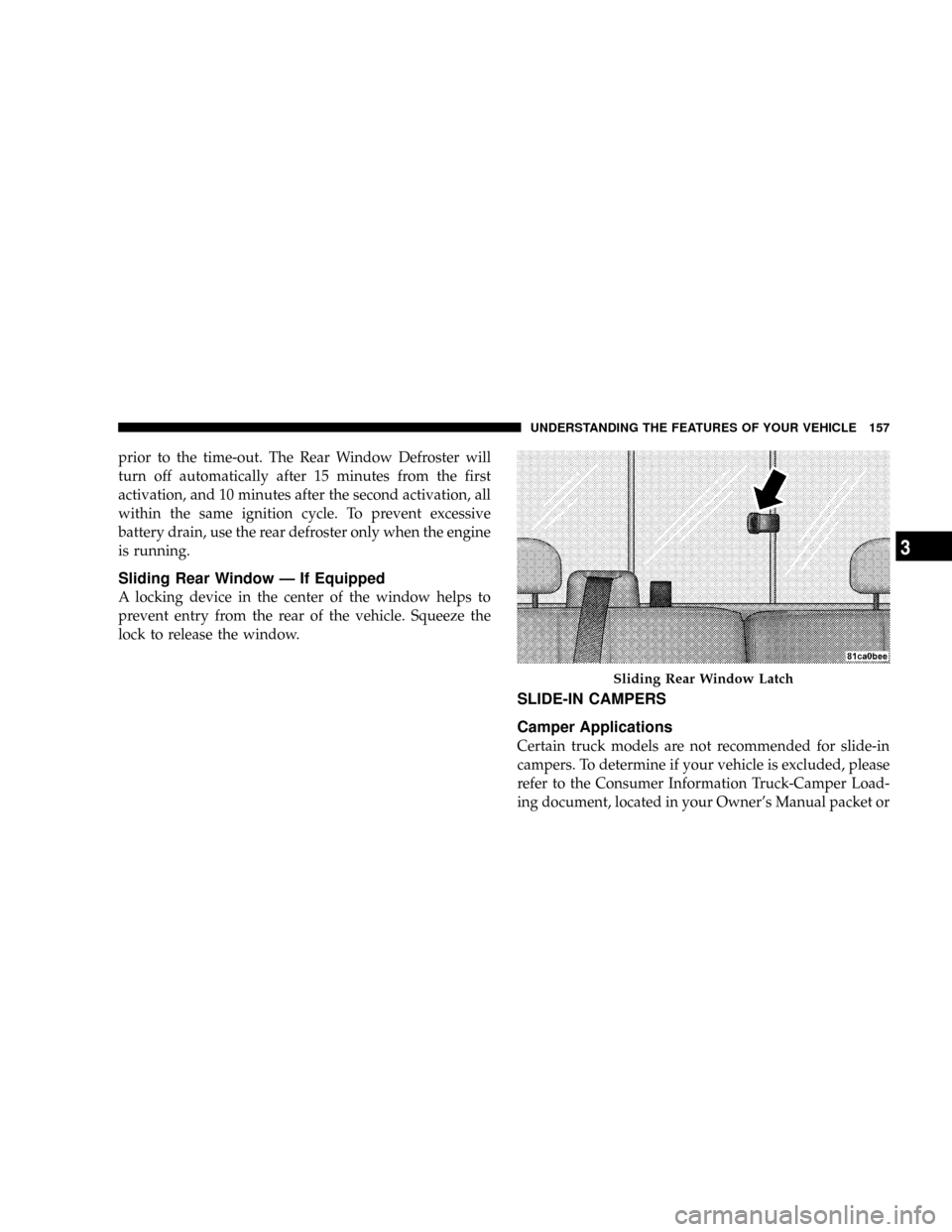
Sliding Rear Window Ð If Equipped
A locking device in the center of the window helps to
prevent entry from the rear of the vehicle. Squeeze the
lock to release the window.
SLIDE-IN CAMPERS
Camper Applications
Certain truck models are not recommended for slide-in
campers. To determine if your vehicle is excluded, please
refer to the Consumer Information Truck-Camper Load-
ing document, located in your Owner's Manual packet or
Sliding Rear Window Latch
UNDERSTANDING THE FEATURES OF YOUR VEHICLE 157
3
Page 170 of 449
INSTRUMENT CLUSTER DESCRIPTION
1. Fuel Gauge
The fuel gauge shows the level of fuel in the fuel tank
when ignition switch is in the ON position.
2. Temperature Gauge
The temperature gauge shows engine coolant tempera-
ture. Any reading within the normal range indicates that
the engine cooling system is operating satisfactorily. The
gauge pointer will likely indicate a higher temperature
when driving in hot weather, up mountain grades, or
when towing a trailer. It should not be allowed to exceed
the upper limits of the normal operating range.
CAUTION!
Do not leave your vehicle unattended with the en-
gine running as you would not be able to react to the
temperature gauge if the engine overheats.3. Turn Signal Indicators
When a turn signal is activated, a right-pointing or
left-pointing arrow lights up and flashes to indicate the
direction of the turn. These indicators also indicate
proper operation of the front and rear turn signal lights.
If either indicator flashes at a faster rate than normal,
check for a defective bulb. If either indicator fails to light
up when the lever is moved, check for a defective fuse or
turn signal LED. A single chime is activated when the
left/right turn signal is left on, with the vehicle speed
greater than 15 mph (24 km/h) for more than one mile.
4. Low Fuel Warning Light
The low fuel warning light will illuminate when the
fuel gauge reads 1/8 of a tank or less. There is a
pointer on the side of this symbol that indicates the
side that your fuel filler door is located.
168 UNDERSTANDING YOUR INSTRUMENT PANEL
Page 171 of 449
5. High Beam Indicator
The high beam indicator will illuminate if the
headlights are on high beam.
6. Seat Belt Reminder Light
The seat belt reminder light will illuminate for
several seconds after the ignition is turned ON as
a reminder to ªbuckle up.º This light will remain
on as long as the seat belt remains unbuckled. If this light
flashes, it indicates a fault in the seat belt system. Have
the system checked by an authorized dealer.
7. Engine Temperature Warning Light
This light warns of an overheated engine condi-
tion. As temperatures rise and the gauge ap-
proachesH(Hot), this indicator will illuminate
and a single chime will sound after reaching a setthreshold. Further overheating will cause the tempera-
ture gauge to passH(Hot), the indicator will continu-
ously flash and a continuous chime will occur until the
engine is allowed to cool.
CAUTION!
Driving with a hot engine cooling system could
damage your vehicle. If the temperature light is on,
safely pull over and stop the vehicle. Idle the vehicle
in neutral with the air conditioner turned off until
the light turns off. If the light remains on, turn the
engine off immediately, and call for service.
UNDERSTANDING YOUR INSTRUMENT PANEL 169
4
Page 172 of 449
WARNING!
A hot engine cooling system is dangerous. You or
others could be badly burned by steam or boiling
coolant. You may want to call a service center if your
vehicle overheats. If you decide to look under the
hood yourself, see Section 7 of this manual. Follow
the warnings under the Cooling System Pressure Cap
paragraph.
8. Speedometer
The speedometer shows the vehicle's speed.
9. Charging System Light
This light shows the status of the electrical charg-
ing system. The light should come on when the
ignition switch is first turned ON and remain on briefly
as a bulb check. If the light stays on or comes on while
driving, turn off some of the vehicle's non-essential
electrical devices or increase engine speed (if at idle). Ifthe charging system light remains on, it means that the
vehicle is experiencing a problem with the charging
system. Obtain SERVICE IMMEDIATELY. See an autho-
rized dealer.
10. Vehicle Security Light
The vehicle security light will flash rapidly for approxi-
mately 15 seconds when the vehicle security alarm is
arming. The light will flash at a slower speed continu-
ously after the alarm is set. The security light will also
come on for about three seconds when the ignition is first
turned ON.
11. Anti-Lock Brake System (ABS)
This light monitors the Anti-Lock Brake System
(ABS). The light will illuminate when the igni-
tion switch is turned to the ON position and
may stay on for as long as four seconds.
If the ABS light remains on or turns on while driving, it
indicates that the Anti-Lock portion of the brake system
170 UNDERSTANDING YOUR INSTRUMENT PANEL
Page 173 of 449
is not functioning and that service is required. However,
the conventional brake system will continue to operate
normally if the BRAKE warning light is not on.
If the ABS light is on, the brake system should be serviced
as soon as possible to restore the benefits of Anti-Lock
brakes. If the ABS light does not illuminate when the
Ignition switch is turned to the ON position, have the
light inspected by an authorized dealer.
12. Oil Pressure Warning Light
The Oil Pressure Warning Light illuminates when
the engine oil pressure has become too low. For a
bulb check, this light will come on momentarily when the
ignition is turned ON. If the light turns on while driving,
stop the vehicle and shut off the engine as soon as
possible. Immediate service should be obtained.
13. Tachometer
The tachometer gauge measures engine revolutions-per-
minute (rpm x 1000).14. Shift Lever Indicator
The electronic shift lever indicator is self-contained
within the instrument cluster. It displays the position of
the automatic transmission shift lever, and the relation of
each position to all other positions. The display will place
a box around the selected transmission range (PRND21).
If the PRNDL displays only the characters PRND21 (no
boxes), have the system checked by an authorized dealer.
15. Trip Odometer
The trip odometer shows individual trip mileage. To
switch from odometer to trip odometer, press and release
the trip odometer button.
To reset a trip odometer, display the trip odometer then
push and hold the button until the display resets (ap-
proximately two seconds).
The odometer will also display messages such as: door
ajar, low wash, No-fuse, Lo Tire (display will toggle
between Lo and Tire for three cycles - if equipped),
UNDERSTANDING YOUR INSTRUMENT PANEL 171
4