2009 CHERY TIGGO heater
[x] Cancel search: heaterPage 1486 of 1903
Downloaded from www.Manualslib.com manuals search engine Operation
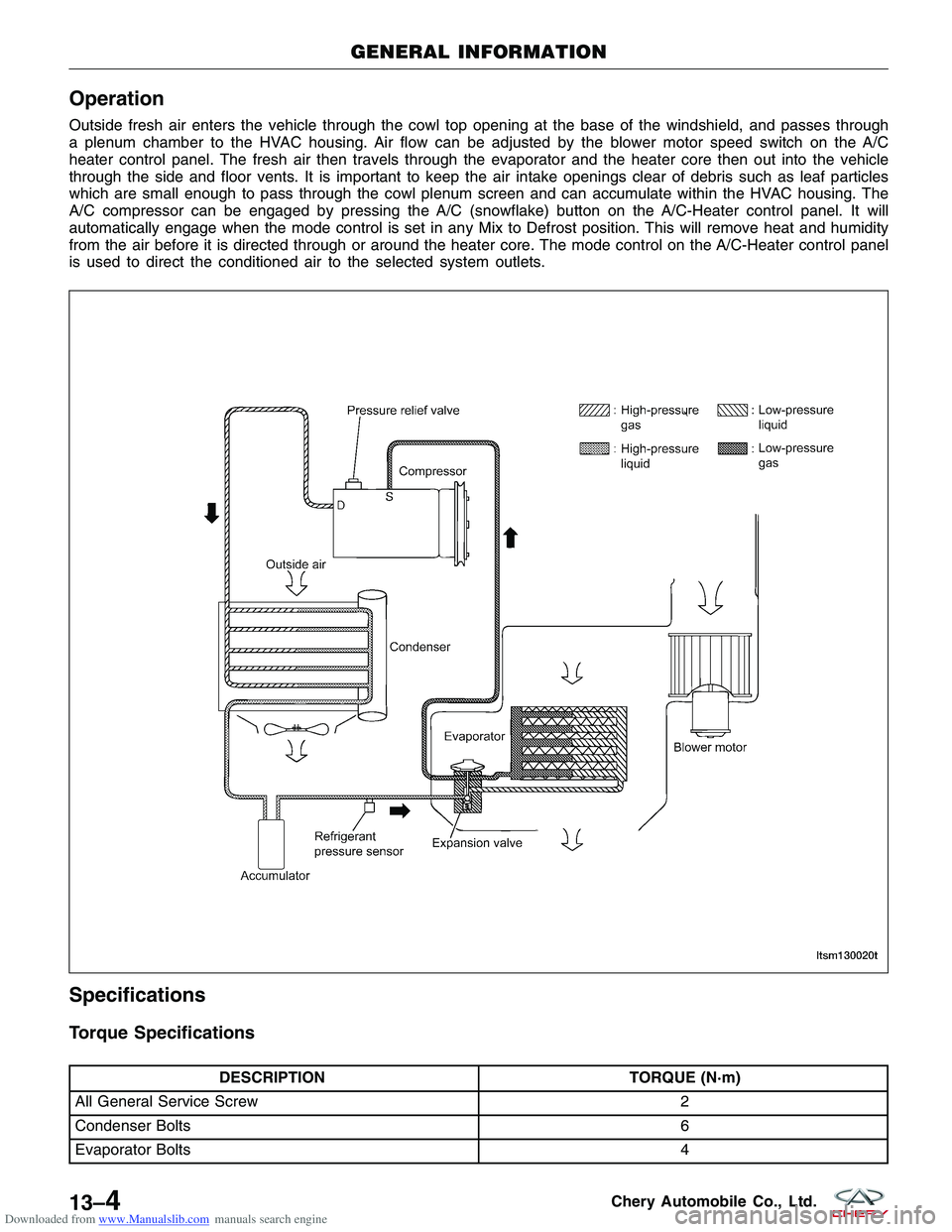
Outside fresh air enters the vehicle through the cowl top opening at the base of the windshield, and passes through
a plenum chamber to the HVAC housing. Air flow can be adjusted by the blower motor speed switch on the A/C
heater control panel. The fresh air then travels through the evaporator and the heater core then out into the vehicle
through the side and floor vents. It is important to keep the air intake openings clear of debris such as leaf particles
which are small enough to pass through the cowl plenum screen and can accumulate within the HVAC housing. The
A/C compressor can be engaged by pressing the A/C (snowflake) button on the A/C-Heater control panel. It will
automatically engage when the mode control is set in any Mix to Defrost position. This will remove heat and humidity
from the air before it is directed through or around the heater core. The mode control on the A/C-Heater control panel
is used to direct the conditioned air to the selected system outlets.
Specifications
Torque Specifications
DESCRIPTIONTORQUE (N·m)
All General Service Screw 2
Condenser Bolts 6
Evaporator Bolts 4
GENERAL INFORMATION
LTSM130020T
13–4Chery Automobile Co., Ltd.
Page 1494 of 1903
Downloaded from www.Manualslib.com manuals search engine DIAGNOSIS & TESTING
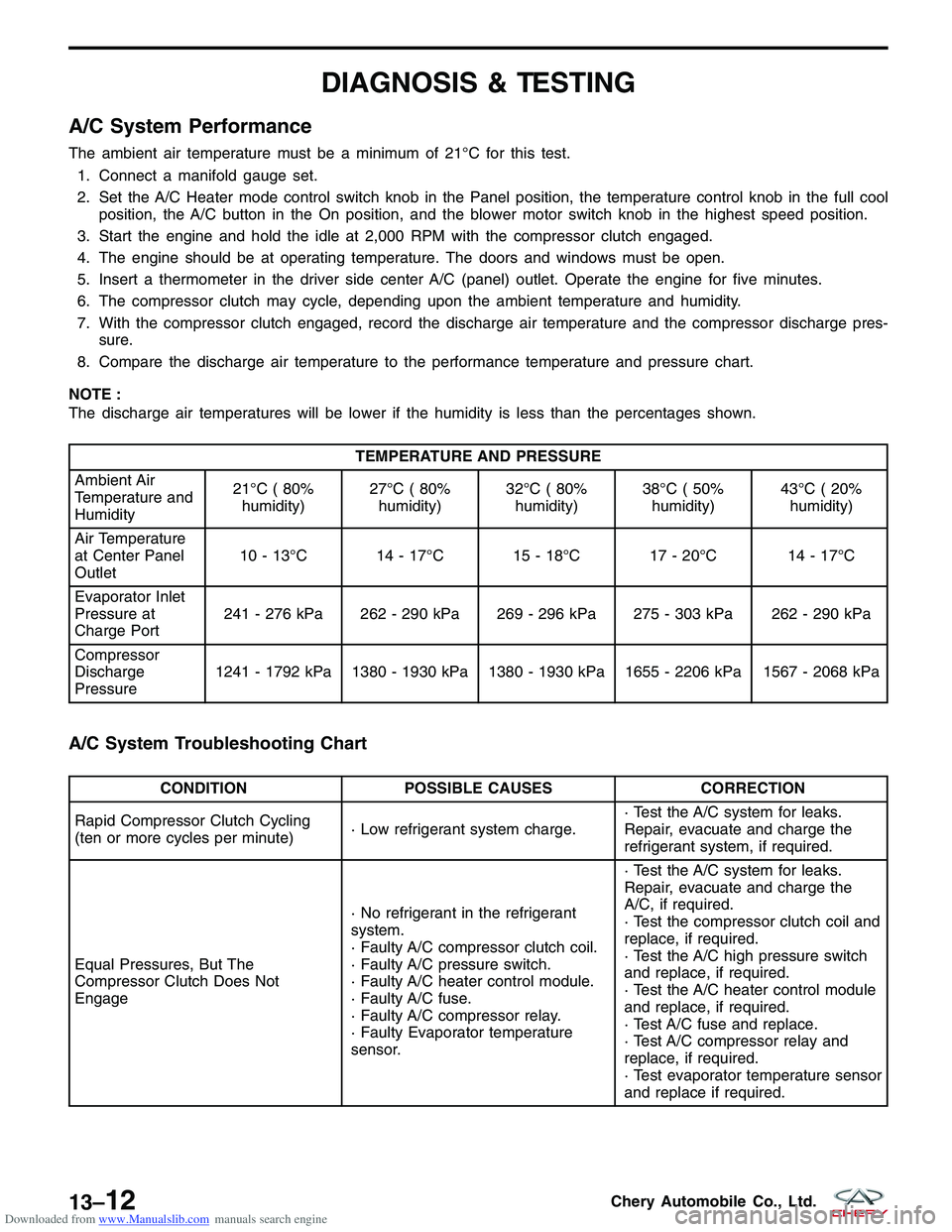
A/C System Performance
The ambient air temperature must be a minimum of 21°C for this test.1. Connect a manifold gauge set.
2. Set the A/C Heater mode control switch knob in the Panel position, the temperature control knob in the full cool position, the A/C button in the On position, and the blower motor switch knob in the highest speed position.
3. Start the engine and hold the idle at 2,000 RPM with the compressor clutch engaged.
4. The engine should be at operating temperature. The doors and windows must be open.
5. Insert a thermometer in the driver side center A/C (panel) outlet. Operate the engine for five minutes.
6. The compressor clutch may cycle, depending upon the ambient temperature and humidity.
7. With the compressor clutch engaged, record the discharge air temperature and the compressor discharge pres- sure.
8. Compare the discharge air temperature to the performance temperature and pressure chart.
NOTE :
The discharge air temperatures will be lower if the humidity is less than the percentages shown.
TEMPERATURE AND PRESSURE
Ambient Air
Temperature and
Humidity 21°C ( 80%
humidity) 27°C ( 80%
humidity) 32°C ( 80%
humidity) 38°C ( 50%
humidity) 43°C ( 20%
humidity)
Air Temperature
at Center Panel
Outlet 10 - 13°C 14 - 17°C 15 - 18°C 17 - 20°C 14 - 17°C
Evaporator Inlet
Pressure at
Charge Port 241 - 276 kPa 262 - 290 kPa 269 - 296 kPa 275 - 303 kPa 262 - 290 kPa
Compressor
Discharge
Pressure 1241 - 1792 kPa 1380 - 1930 kPa 1380 - 1930 kPa 1655 - 2206 kPa 1567 - 2068 kPa
A/C System Troubleshooting Chart
CONDITION
POSSIBLE CAUSES CORRECTION
Rapid Compressor Clutch Cycling
(ten or more cycles per minute) · Low refrigerant system charge.· Test the A/C system for leaks.
Repair, evacuate and charge the
refrigerant system, if required.
Equal Pressures, But The
Compressor Clutch Does Not
Engage · No refrigerant in the refrigerant
system.
· Faulty A/C compressor clutch coil.
· Faulty A/C pressure switch.
· Faulty A/C heater control module.
· Faulty A/C fuse.
· Faulty A/C compressor relay.
· Faulty Evaporator temperature
sensor.· Test the A/C system for leaks.
Repair, evacuate and charge the
A/C, if required.
· Test the compressor clutch coil and
replace, if required.
· Test the A/C high pressure switch
and replace, if required.
· Test the A/C heater control module
and replace, if required.
· Test A/C fuse and replace.
· Test A/C compressor relay and
replace, if required.
· Test evaporator temperature sensor
and replace if required.
13–12Chery Automobile Co., Ltd.
Page 1496 of 1903
Downloaded from www.Manualslib.com manuals search engine Heater Performance
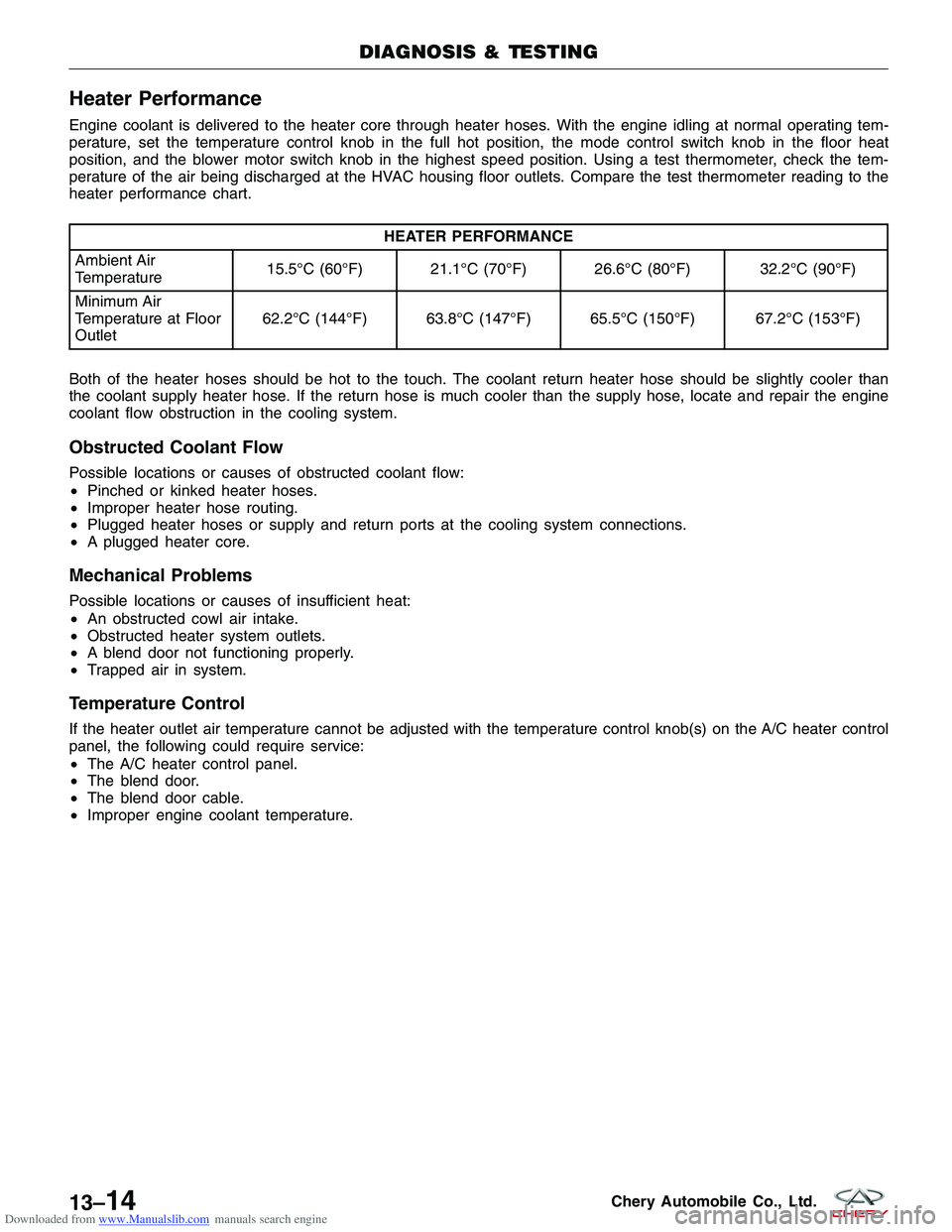
Engine coolant is delivered to the heater core through heater hoses. With the engine idling at normal operating tem-
perature, set the temperature control knob in the full hot position, the mode control switch knob in the floor heat
position, and the blower motor switch knob in the highest speed position. Using a test thermometer, check the tem-
perature of the air being discharged at the HVAC housing floor outlets. Compare the test thermometer reading to the
heater performance chart.
HEATER PERFORMANCE
Ambient Air
Temperature 15.5°C (60°F) 21.1°C (70°F) 26.6°C (80°F) 32.2°C (90°F)
Minimum Air
Temperature at Floor
Outlet 62.2°C (144°F) 63.8°C (147°F) 65.5°C (150°F) 67.2°C (153°F)
Both of the heater hoses should be hot to the touch. The coolant return heater hose should be slightly cooler than
the coolant supply heater hose. If the return hose is much cooler than the supply hose, locate and repair the engine
coolant flow obstruction in the cooling system.
Obstructed Coolant Flow
Possible locations or causes of obstructed coolant flow:
• Pinched or kinked heater hoses.
• Improper heater hose routing.
• Plugged heater hoses or supply and return ports at the cooling system connections.
• A plugged heater core.
Mechanical Problems
Possible locations or causes of insufficient heat:
•An obstructed cowl air intake.
• Obstructed heater system outlets.
• A blend door not functioning properly.
• Trapped air in system.
Temperature Control
If the heater outlet air temperature cannot be adjusted with the temperature control knob(s) on the A/C heater control
panel, the following could require service:
•The A/C heater control panel.
• The blend door.
• The blend door cable.
• Improper engine coolant temperature.
DIAGNOSIS & TESTING
13–14Chery Automobile Co., Ltd.
Page 1502 of 1903
Downloaded from www.Manualslib.com manuals search engine 1 - Inlet Shell Shield
2 - Inlets Shrouds
3 - Bolt (M6)
4 - Inlet Shell Assembly
5 - Recirculation Door Actuator
6 - Mixed Door Lever
7 - Defrost Door Lever
8 - Water Hose Clamp
9 - Blower Control Dial
10 - Defrost Door Linkage
11 - Mode Door Dial
12 - Plastic Washer
13 - Mode Door Dial Linkage
14 - Mode Door Dial Lever
15 - Evaporator Assembly
16 - HVAC Control Panel
17 - Temperature Control Dial Cable
18 - Mode Door Cable
19 - Outlet Assembly
20 - Clamp21 - Left Outlet
22 - Right Outlet
23 - Evaporator Assembly Upper Cover
24 - Drain Inner Hose Assembly
25 - Rubber Drain Inside Hose
26 - Rubber Drain Outside Hose
27 - Evaporator Assembly Lower Cover
28 - Evaporator Core
29 - Sealed Gasket
30 - Sponge
31 - Expansion Valve
32 - Blower Motor Resistor
33 - Blower Motor
34 - HVAC Filter
35 - Heater Core
36 - HVAC Control Panel Bolt
37 - HVAC Control Panel
38 - Clamp
39 - Water Hose Sealed Gasket
40 - Sponge
GENERAL INFORMATION
LTSM130019
13–20Chery Automobile Co., Ltd.
Page 1503 of 1903
Downloaded from www.Manualslib.com manuals search engine Operation
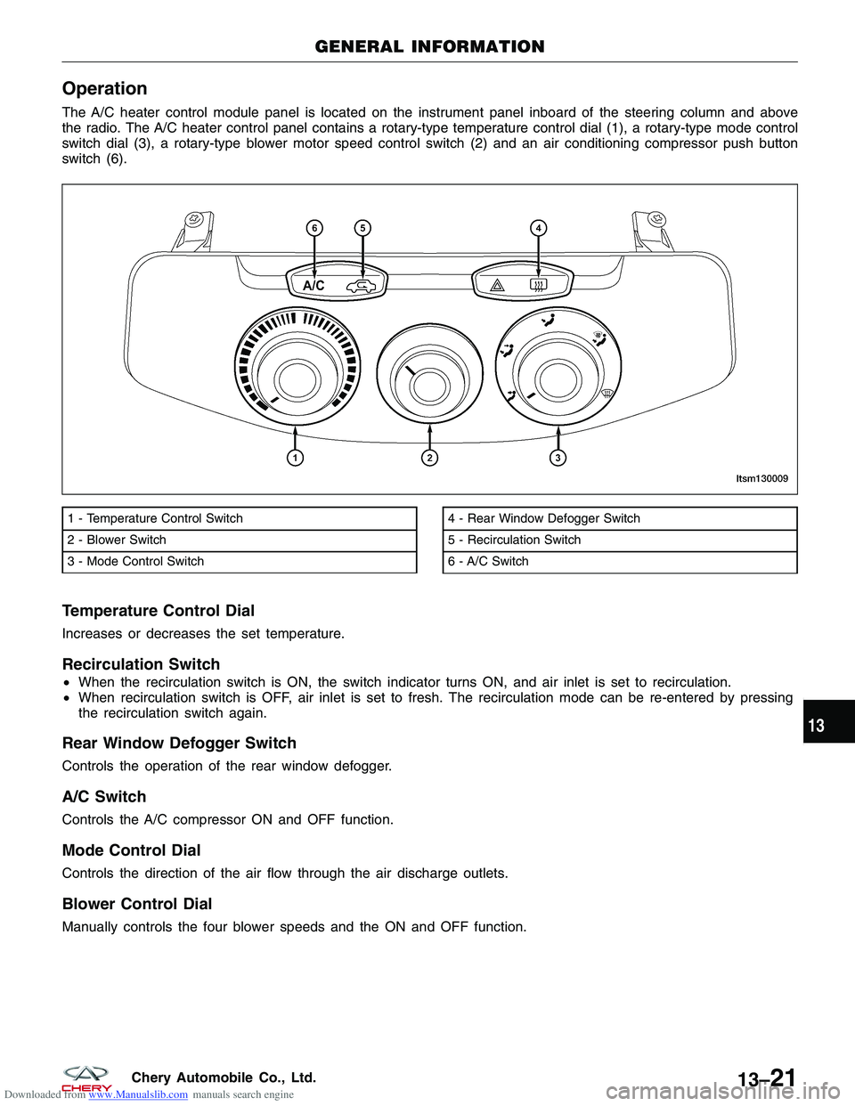
The A/C heater control module panel is located on the instrument panel inboard of the steering column and above
the radio. The A/C heater control panel contains a rotary-type temperature control dial (1), a rotary-type mode control
switch dial (3), a rotary-type blower motor speed control switch (2) and an air conditioning compressor push button
switch (6).
Temperature Control Dial
Increases or decreases the set temperature.
Recirculation Switch
•When the recirculation switch is ON, the switch indicator turns ON, and air inlet is set to recirculation.
• When recirculation switch is OFF, air inlet is set to fresh. The recirculation mode can be re-entered by pressing
the recirculation switch again.
Rear Window Defogger Switch
Controls the operation of the rear window defogger.
A/C Switch
Controls the A/C compressor ON and OFF function.
Mode Control Dial
Controls the direction of the air flow through the air discharge outlets.
Blower Control Dial
Manually controls the four blower speeds and the ON and OFF function.
1 - Temperature Control Switch
2 - Blower Switch
3 - Mode Control Switch4 - Rear Window Defogger Switch
5 - Recirculation Switch
6 - A/C Switch
GENERAL INFORMATION
LTSM130009
13
13–21Chery Automobile Co., Ltd.
Page 1508 of 1903
Downloaded from www.Manualslib.com manuals search engine GENERAL INFORMATION
Description
All models are equipped with a common HVAC housing assembly that combines A/C and heating capabilities into a
single unit mounted within the passenger compartment. The HVAC housing assembly consists of three separate
housings:
•HVAC housing — The HVAC housing is mounted to the dash panel behind the instrument panel and contains
the A/C evaporator. The HVAC housing has mounting provisions for the air inlet housing, blower motor and the
air distribution housing.
• Air distribution housing — The air distribution housing is mounted to the rear of the HVAC housing and con-
tains the heater core, blend-air and mode-air doors and door linkage.
• Air inlet housing — The air inlet housing is mounted to the passenger side end of the HVAC housing. The air
inlet housing contains the recirculation-air door and actuator.
Operation
The A/C system is designed for the use of a non-CFC, R-134a refrigerant and uses an A/C evaporator to cool and
dehumidify the incoming air prior to blending it with the heated air. Temperature control determines the discharge air
temperature by operating the temperature control cable, which moves the blend-air door. This allows an almost
immediate control of the output air temperature of the system. The mode door cable operates the mode-air doors
which direct the flow of the conditioned air out the various air outlets, depending on the mode selected. When
equipped with A/C, the recirculation door actuator operates the recirculation-air door which closes off the fresh air
intake and recirculates the air already inside the vehicle. The electric recirculation door actuator and the blower motor
are connected to the vehicle electrical system by the instrument panel wire harness. The blower motor controls the
velocity of air flowing through the HVAC housing assembly by spinning the blower wheel within the HVAC housing at
the selected speed by use of the blower motor resistor, which is around the blower motor.
The air distribution housing must be removed from the HVAC housing and disassembled for service of the blend-air
and mode-air doors. The air inlet housing must be removed from the HVAC housing and disassembled for service of
the recirculation-air door. The HVAC housing must be removed from the vehicle and disassembled for service of the
A/C evaporator.
Specifications
Torque Specifications
DESCRIPTION TORQUE (N·m)
All General Service Screws 2
Evaporator Bolts 4
Expansion Valve Bolts 10
Pipeline Stent 4
Refrigerant Lines To A/C Accumulator 6
Condenser Bolts 6
Refrigerant Lines To A/C Compressor Bolt 30
Refrigerant Lines 10
Refrigerant Lines To A/C Evaporator Bolt 25
13–26Chery Automobile Co., Ltd.
Page 1510 of 1903
Downloaded from www.Manualslib.com manuals search engine DIAGNOSIS & TESTING
Blower Motor Electrical Troubleshooting
To determine if an open condition exists within the blower motor circuit wiring, it is necessary to disconnect the neg-
ative battery cable and check for continuity within the blower motor circuits using an ohmmeter.
Possible causes of an inoperative blower motor include the following:
•Open fuse
• Inoperative blower motor switch
• Inoperative blower motor resistor
• Inoperative blower motor
• Inoperative blower motor circuit wiring or wiring harness electrical connectors
Blower Motor Noise
To determine if the blower motor is the source of the noise, simply switch the blower motor from Off to On. To verify
that the blower motor is the source of the noise, unplug the blower motor wire harness connector and operate the
heater-A/C system. If the noise goes away, possible causes include:
•Foreign material on fresh air inlet screen
• Foreign material in blower wheel
• Foreign material in HVAC housing
• Incorrect blower motor mounting
• Deformed or damaged blower wheel
• Worn blower motor bearings or brushes
Blower Motor Vibration
Possible causes of a blower motor vibration include:
•Incorrect blower motor mounting
• Foreign material in blower wheel
• Deformed or damaged blower wheel
• Worn blower motor bearings
13–28Chery Automobile Co., Ltd.
Page 1511 of 1903
Downloaded from www.Manualslib.com manuals search engine ON-VEHICLE SERVICE
HVAC Housing
Removal & Installation
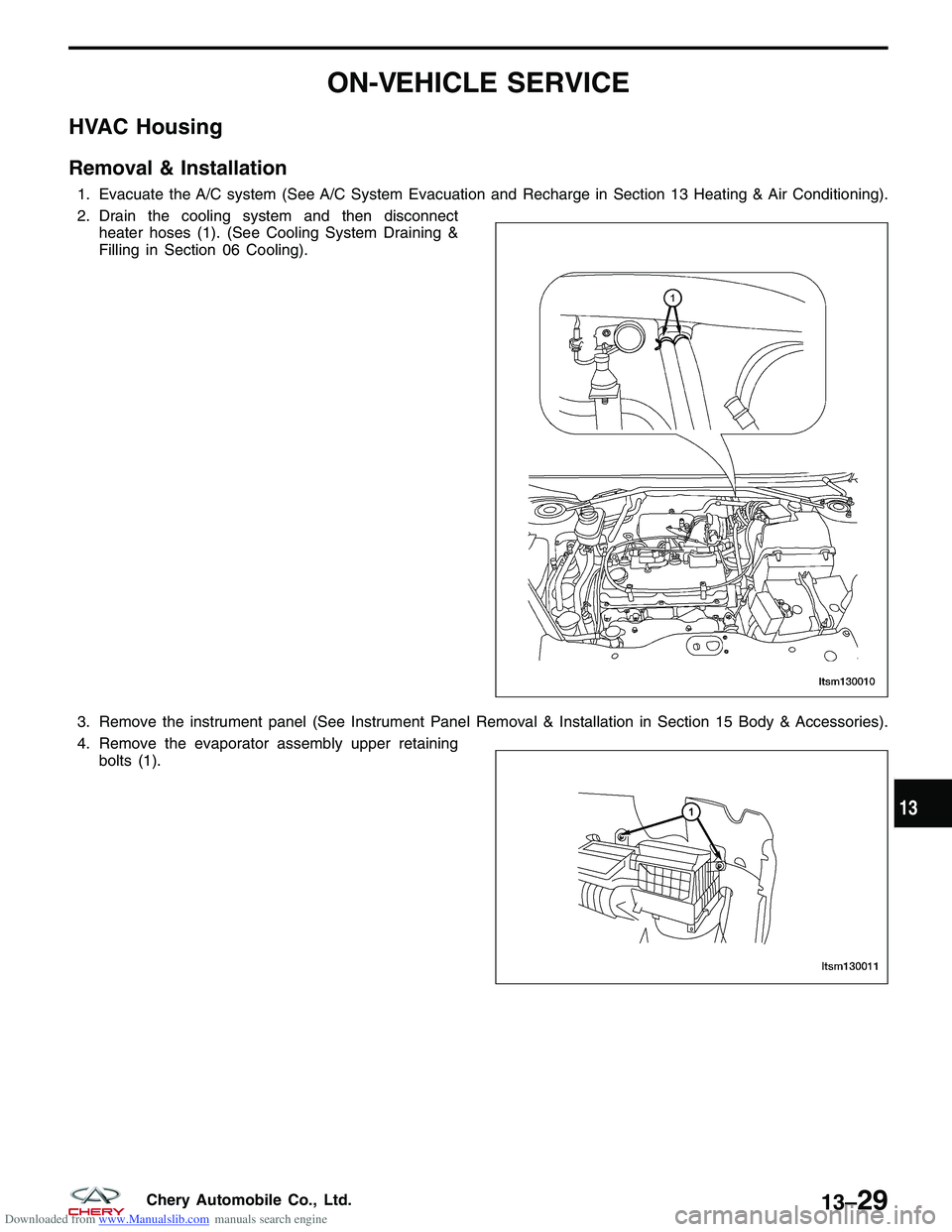
1. Evacuate the A/C system (See A/C System Evacuation and Recharge in Section 13 Heating & Air Conditioning).
2. Drain the cooling system and then disconnectheater hoses (1). (See Cooling System Draining &
Filling in Section 06 Cooling).
3. Remove the instrument panel (See Instrument Panel Removal & Installation in Section 15 Body & Accessories).
4. Remove the evaporator assembly upper retaining bolts (1).
LTSM130010
LTSM130011
13
13–29Chery Automobile Co., Ltd.