2009 CHERY TIGGO wheel torque
[x] Cancel search: wheel torquePage 1349 of 1903
Downloaded from www.Manualslib.com manuals search engine GENERAL INFORMATION
Description
Tires are designed and engineered for each specific vehicle. They provide the best overall performance for normal
operation. The ride and handling characteristics match the vehicle’s requirements. With proper care they will give
excellent reliability, traction, skid resistance, and tread life.
Tire Identification
•Tire type, size, load index and speed rating are encoded in the letters and numbers imprinted on the side wall
of the tire.
Spare Tire
• A full size spare tire and wheel assembly is standard equipment on this vehicle. The original tire should be
repaired or replaced at the first opportunity, then reinstalled.
Operation
Driving habits have more effect on tire life than any other factor. Careful drivers will obtain, in most cases, much
greater mileage than severe use or careless drivers. A few of the driving habits which will shorten the life of any tire
are:
•Rapid acceleration
• Severe application of brakes
• High-speed driving
• Taking turns at excessive speeds
• Striking curbs and other obstacles
• Operating vehicle with over or under inflated tire pressures
Specifications
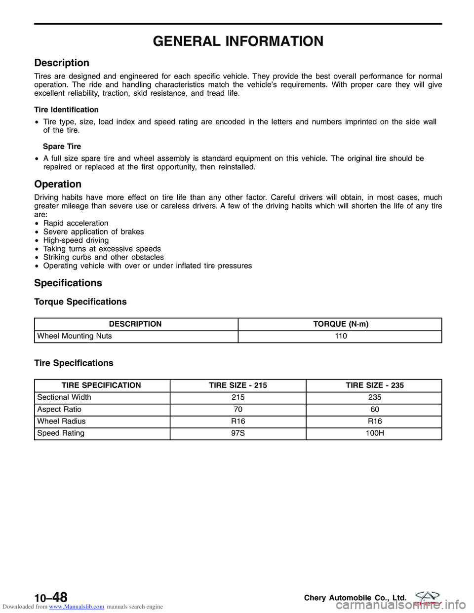
Torque Specifications
DESCRIPTION TORQUE (N·m)
Wheel Mounting Nuts 110
Tire Specifications
TIRE SPECIFICATIONTIRE SIZE - 215TIRE SIZE - 235
Sectional Width 215235
Aspect Ratio 7060
Wheel Radius R16R16
Speed Rating 97S100H
10–48Chery Automobile Co., Ltd.
Page 1359 of 1903
Downloaded from www.Manualslib.com manuals search engine DIAGNOSIS & TESTING
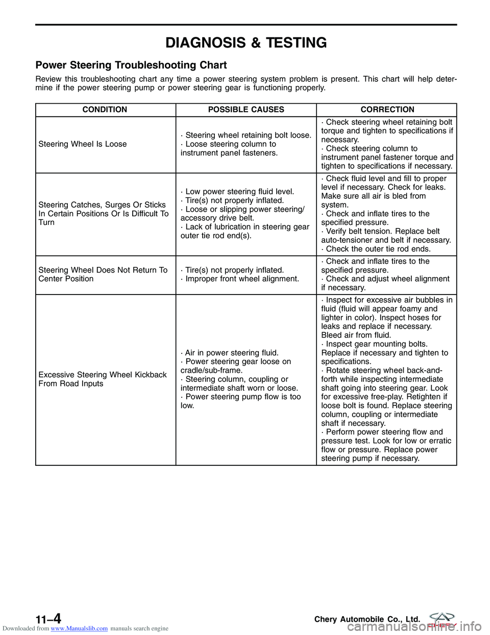
Power Steering Troubleshooting Chart
Review this troubleshooting chart any time a power steering system problem is present. This chart will help deter-
mine if the power steering pump or power steering gear is functioning properly.
CONDITIONPOSSIBLE CAUSES CORRECTION
Steering Wheel Is Loose · Steering wheel retaining bolt loose.
· Loose steering column to
instrument panel fasteners.· Check steering wheel retaining bolt
torque and tighten to specifications if
necessary.
· Check steering column to
instrument panel fastener torque and
tighten to specifications if necessary.
Steering Catches, Surges Or Sticks
In Certain Positions Or Is Difficult To
Turn · Low power steering fluid level.
· Tire(s) not properly inflated.
· Loose or slipping power steering/
accessory drive belt.
· Lack of lubrication in steering gear
outer tie rod end(s).· Check fluid level and fill to proper
level if necessary. Check for leaks.
Make sure all air is bled from
system.
· Check and inflate tires to the
specified pressure.
· Verify belt tension. Replace belt
auto-tensioner and belt if necessary.
· Check the outer tie rod ends.
Steering Wheel Does Not Return To
Center Position · Tire(s) not properly inflated.
· Improper front wheel alignment.· Check and inflate tires to the
specified pressure.
· Check and adjust wheel alignment
if necessary.
Excessive Steering Wheel Kickback
From Road Inputs · Air in power steering fluid.
· Power steering gear loose on
cradle/sub-frame.
· Steering column, coupling or
intermediate shaft worn or loose.
· Power steering pump flow is too
low.· Inspect for excessive air bubbles in
fluid (fluid will appear foamy and
lighter in color). Inspect hoses for
leaks and replace if necessary.
Bleed air from fluid.
· Inspect gear mounting bolts.
Replace if necessary and tighten to
specifications.
· Rotate steering wheel back-and-
forth while inspecting intermediate
shaft going into steering gear. Look
for excessive free-play. Retighten if
loose bolt is found. Replace steering
column, coupling or intermediate
shaft if necessary.
· Perform power steering flow and
pressure test. Look for low or erratic
flow or pressure. Replace power
steering pump if necessary.
11 –4Chery Automobile Co., Ltd.
Page 1365 of 1903
Downloaded from www.Manualslib.com manuals search engine Operation
The steering column is the mechanical linkage between the steering wheel and the steering gear. The steering col-
umn shaft then connects the steering column to the steering gear. The tilt function of the steering column is con-
trolled by a mechanical lever on the underside of the steering column, which uses a cam to lock and unlock the
steering column.
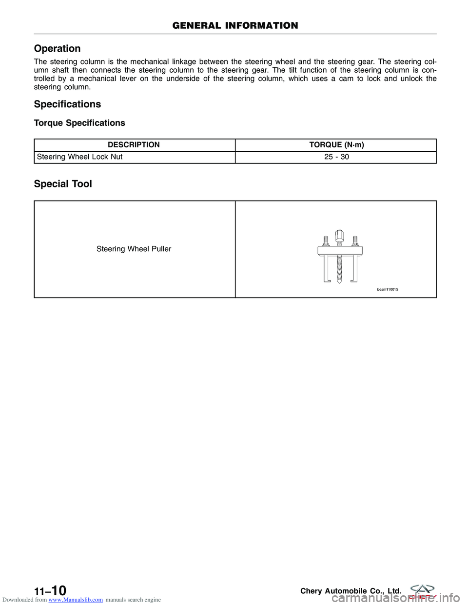
Specifications
Torque Specifications
DESCRIPTIONTORQUE (N·m)
Steering Wheel Lock Nut 25 - 30
Special Tool
Steering Wheel Puller
GENERAL INFORMATION
11 –10Chery Automobile Co., Ltd.
Page 1368 of 1903
Downloaded from www.Manualslib.com manuals search engine Inspection - Steering System
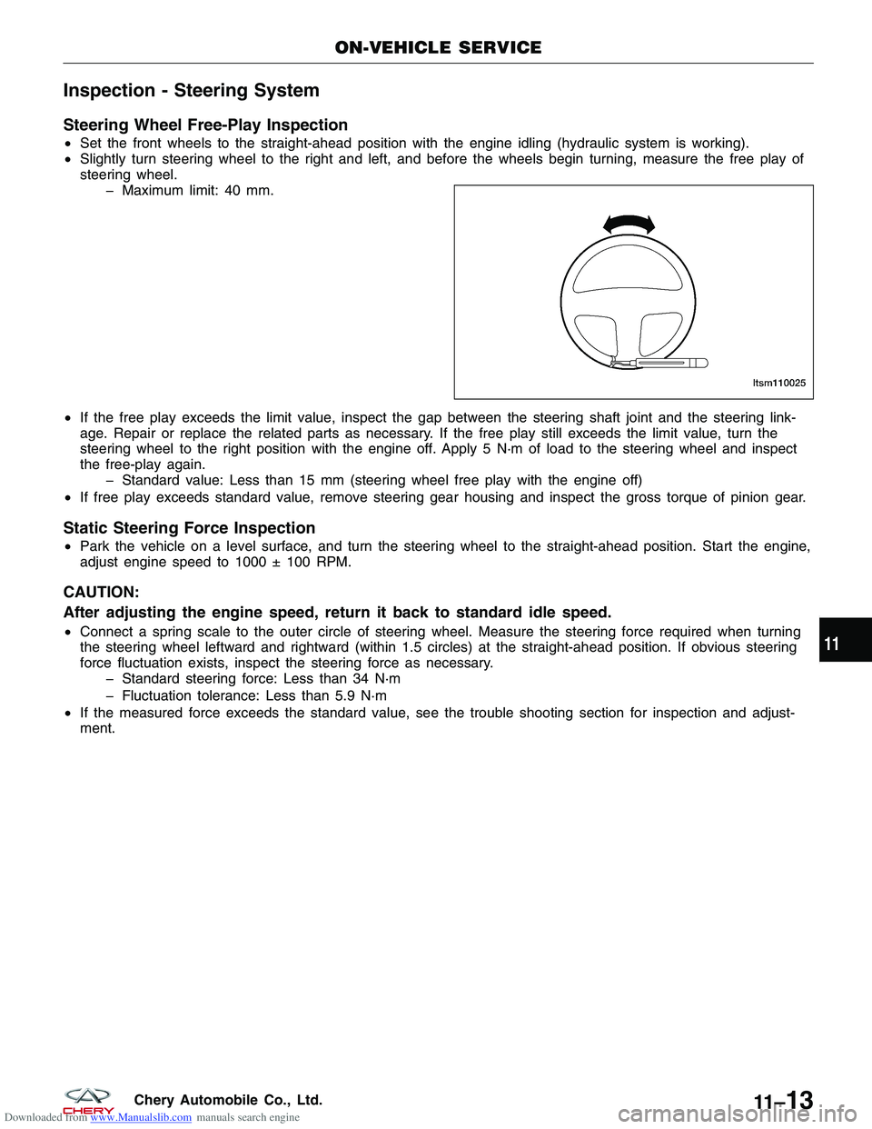
Steering Wheel Free-Play Inspection
•Set the front wheels to the straight-ahead position with the engine idling (hydraulic system is working).
• Slightly turn steering wheel to the right and left, and before the wheels begin turning, measure the free play of
steering wheel.
� Maximum limit: 40 mm.
• If the free play exceeds the limit value, inspect the gap between the steering shaft joint and the steering link-
age. Repair or replace the related parts as necessary. If the free play still exceeds the limit value, turn the
steering wheel to the right position with the engine off. Apply 5 N·m of load to the steering wheel and inspect
the free-play again.
� Standard value: Less than 15 mm (steering wheel free play with the engine off)
• If free play exceeds standard value, remove steering gear housing and inspect the gross torque of pinion gear.
Static Steering Force Inspection
•Park the vehicle on a level surface, and turn the steering wheel to the straight-ahead position. Start the engine,
adjust engine speed to 1000 ± 100 RPM.
CAUTION:
After adjusting the engine speed, return it back to standard idle speed.
•Connect a spring scale to the outer circle of steering wheel. Measure the steering force required when turning
the steering wheel leftward and rightward (within 1.5 circles) at the straight-ahead position. If obvious steering
force fluctuation exists, inspect the steering force as necessary.
� Standard steering force: Less than 34 N·m
� Fluctuation tolerance: Less than 5.9 N·m
• If the measured force exceeds the standard value, see the trouble shooting section for inspection and adjust-
ment.
ON-VEHICLE SERVICE
LTSM110025
11
11 –13Chery Automobile Co., Ltd.
Page 1374 of 1903
Downloaded from www.Manualslib.com manuals search engine GENERAL INFORMATION
Description
The steering gear used is the rack-and-pinion type with power assist. It is mounted on the front suspension sub-
frame. The outer ends of the outer tie rods attach to the front knuckles.
NOTE :
The power steering gear should not be serviced or adjusted. If a malfunction or steering fluid leak occurs with the
steering gear, the complete steering gear needs to be replaced.
Operation
The steering wheel turns the pinion. The rack is a long flat bar with geared teeth on one side. The rack teeth mesh
with the teeth on the pinion gear. Rotation of the pinion moves the rack from left to right and right to left. The tie rod
then causes the wheels to turn to the left or right.
Specifications
Torque Specifications
DESCRIPTIONTORQUE (N·m)
Inlet / Outlet Pipe Nut 25 - 30
Intermediate Shaft Bolt 25 - 30
Steering Gear to Sub-Frame Bolts 70 - 80
Sub-Frame Assembly Bolts 180 ± 15
Tie Rod End Nut 32 - 38
Tie Rod Jam Nut 15
Wheel Mounting Nuts 110
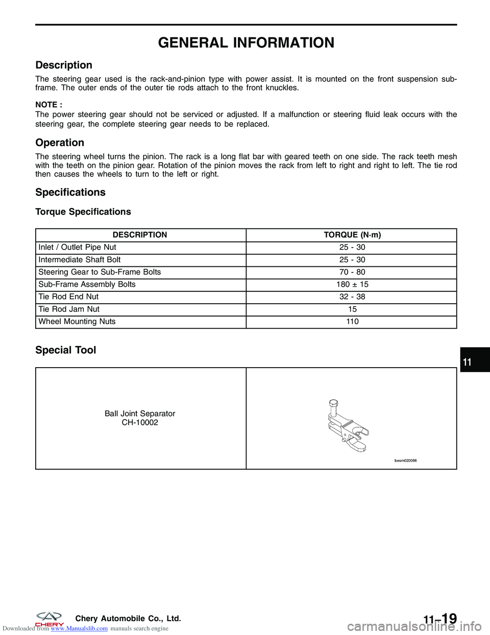
Special Tool
Ball Joint Separator
CH-10002
11
11 –19Chery Automobile Co., Ltd.
Page 1387 of 1903
Downloaded from www.Manualslib.com manuals search engine GENERAL INFORMATION
Description
The power steering pump is a constant flow rate and displacement vane type pump. The pump reservoir is detached
from the pump body. The pump is connected to the steering gear by the pressure and return lines.
Operation
The power steering pump is mounted to the engine and driven by the engine accessory drive belt. Power steering
fluid enters the pump from the reservoir. The power steering fluid is then trapped between the pump vanes and
moved to the high-pressure side of the pump creating a flow of steering fluid. The restriction of this flow by the
steering gear creates the pressure that provides the steering assist.
CAUTION:
•Operating the power steering with a low steering fluid level will damage the power steering sys-
tem.
• Holding the steering wheel in the full lock position for more than 3 seconds will damage the
power steering system.
Specifications
Torque Specifications
DESCRIPTION TORQUE (N·m)
Power Steering Pressure Line To Steering Gear 27 - 33
Power Steering Return Line To Steering Gear 27 - 33
Power Steering Pressure Line To Power Steering Pump 40 - 50
Power Steering Pump Mounting Bolts 20 - 30
Pressure/Return Hose Routing Clamp Screws To Cross
Member 10-15
Fluid Specifications
DESCRIPTION
CAPACITY (L)
Power Steering Fluid (ATF III) 1.1
11 –32Chery Automobile Co., Ltd.
Page 1399 of 1903
Downloaded from www.Manualslib.com manuals search engine Specifications
Torque Specifications
DESCRIPTIONTORQUE (N·m)
Dust Shield Bolts 6.5 - 8.5
Locating Screws (Brake Rotor) 6 - 12
Brake Flex Hose Fitting - Front Caliper 19
Brake Flex Hose Banjo Bolt - Rear Caliper 20
Brake Pedal/Booster Mounting Nuts 25
Brake Tube Nuts 10
Disc Brake Caliper Adapter Bracket (To Knuckle) - Front 63
Disc Brake Caliper Adapter Bracket (To Support) - Rear 63
Disc Brake Caliper Guide Pin Bolts - Front 31 - 38
Disc Brake Caliper Guide Pin Bolts - Rear 23
Disc Brake Caliper Bleeder Screw 9 - 11
Fluid Reservoir Mounting Screw 11
Master Cylinder Mounting Nuts 23
Parking Brake Lever Mounting Nuts 6 - 12
Rear Brake Backing Plate Bolts 20
Wheel Mounting Nuts 110
Rotor Specifications
BRAKE ROTORROTOR
THICKNESS MINIMUM ROTOR
THICKNESS ROTOR DIAMETER ROTOR RUNOUT
Front Rotor 25 mm23 mm265 mm 0.1 mm
Rear Rotor 9 mm7 mm303 mm 0.1 mm
Brake Pad/Lining Specifications
Front Brake
APPLICATION SPECIFICATION (mm)
Brake Caliper Piston Diameter 57
Brake Rotor Diameter 265
Brake Rotor Thickness (New) 25
Min. Thickness Of Brake Rotor 23
Maximum Rotor Runout 0.1
Front Brake Pad Thickness (New) 17.8
Min. Thickness Of Front Brake Pad 7
GENERAL INFORMATION
12–4Chery Automobile Co., Ltd.
Page 1431 of 1903
Downloaded from www.Manualslib.com manuals search engine Operation
ABS Braking
•ABS operation is available at all vehicle speeds above 20 km/h. If a wheel locking tendency is detected during
a brake application, the brake system enters the ABS mode. During ABS braking, hydraulic pressure in the four
wheel circuits is modulated to prevent any wheel from locking. Each wheel circuit is designed with a set of
electric solenoids to allow modulation. The system can build and release pressure at each wheel, depending on
signals generated by the wheel speed sensors at each wheel and received at the ABS Module.
• There are a few performance characteristics of the ABS that may at first seem abnormal, but in fact are nor-
mal. These characteristics are described below.
� If the electrical system malfunctions, the Fail-Safe function is activated, the ABS becomes inoperative and
the ABS warning lamp turns on.
� During ABS operation, the brake pedal may vibrate lightly and a mechanical noise may be heard. This is normal.
� Stopping distance may be longer than that of vehicles without ABS when vehicle drives on rough, gravel, or snow-covered (fresh, deep snow) roads.
Specifications
Torque Specifications
DESCRIPTION TORQUE (N·m)
ABS Mounting Bolt (To Bracket) 10
ABS Mounting Bracket Screws (To Frame) 20
ABS Mounting Bracket Screw And Nut (To Frame) 20
ABS Wheel Speed Sensor Head Mounting Screw - Rear 10
Brake Tube Nuts 10
Wheel Mounting Nuts 110
GENERAL INFORMATION
12–36Chery Automobile Co., Ltd.