Page 977 of 1903
Downloaded from www.Manualslib.com manuals search engine Diagnostic Procedure
1.CHECK A/T SOLENOID SIGNAL
• With the scan tool, select view DTC and data stream for A/T.
• Start the engine.
• Monitor the gear position while driving, and compare to the following table.
TRANSAXLE GEAR POSITION/SOLENOID ACTIVATION
SELECT
POSITION RANGESHIFT
SOLENOID VA LV E 1 SHIFT
SOLENOID VA LV E 2 SHIFT
SOLENOID VA LV E 3 SHIFT
SOLENOID VA LV E 4
P0- - # -
RR----
N0- - # -
D 1- - # #
2- # - #
3----
4# # -
-
•
#: Operating component
Is the check result normal?
Ye s>>The condition that caused this DTC is intermittent (See Diagnostic Help in Section 08 Transaxle &
Transfer Case).
No
>>Go to the next step.
2.ACTUATE TEST
• Stop the engine.
• Turn ignition switch on.
• With X-431 scan tool, perform the solenoid actuate test.
• The solenoid actuation should be heard.
Is the check result normal?
Ye s>>Go to step 5.
No
>>Go to the next step.
DIAGNOSIS & TESTING
08–34Chery Automobile Co., Ltd.
Page 1044 of 1903
Downloaded from www.Manualslib.com manuals search engine Diagnostic Procedure
1.CHECK A/T FLUID PRESSURE SENSOR SIGNAL
• With the scan tool, select view DTC and data stream for A/T.
• Start vehicle and monitor the value of �INPUT SPEED SENSOR�.
ITEM CONDITIONDISPLAY
VALUE
Fluid Pressure Ignition switch
on, not running
Below 0.2 bar
• Engine: Idle
• TFT: 31°C
• ECT: 30°C Approximately
0.05 bar
Is the check result normal?
Ye s>>The condition that caused this DTC is intermittent (See Diagnostic Help in Section 08 Transaxle &
Transfer Case).
No
>>Go to the next step.
2.CHECK FLUID PRESSURE SENSOR ELECTRICAL CONNECTOR
• Stop vehicle and turn ignition switch off.
• Disconnect fluid pressure sensor 2 connector.
• Inspect the electrical connector for damage.
Is the electrical connector OK?
Ye s>>Go to the next step.
No
>>Repair or replace the electrical connector
as necessary.
DIAGNOSIS & TESTING
LTSMD080021
08
08–101Chery Automobile Co., Ltd.
Page 1108 of 1903
Downloaded from www.Manualslib.com manuals search engine Diagnostic Procedure
1.CHECK A/T INPUT SIGNAL
• With the scan tool, select view DTC and data stream for A/T.
• Vehicle start and read out the value of �INPUT SPEED SENSOR�.
ITEM CONDITIONDISPLAY
VALUE
Input speed sensor During driving
(lock-up ON) Approximately
matches the
engine speed.
Is the check result normal?
Ye s>>The condition that caused this DTC is intermittent (See Diagnostic Help in Section 08 Transaxle &
Transfer Case).
No
>>Go to the next step.
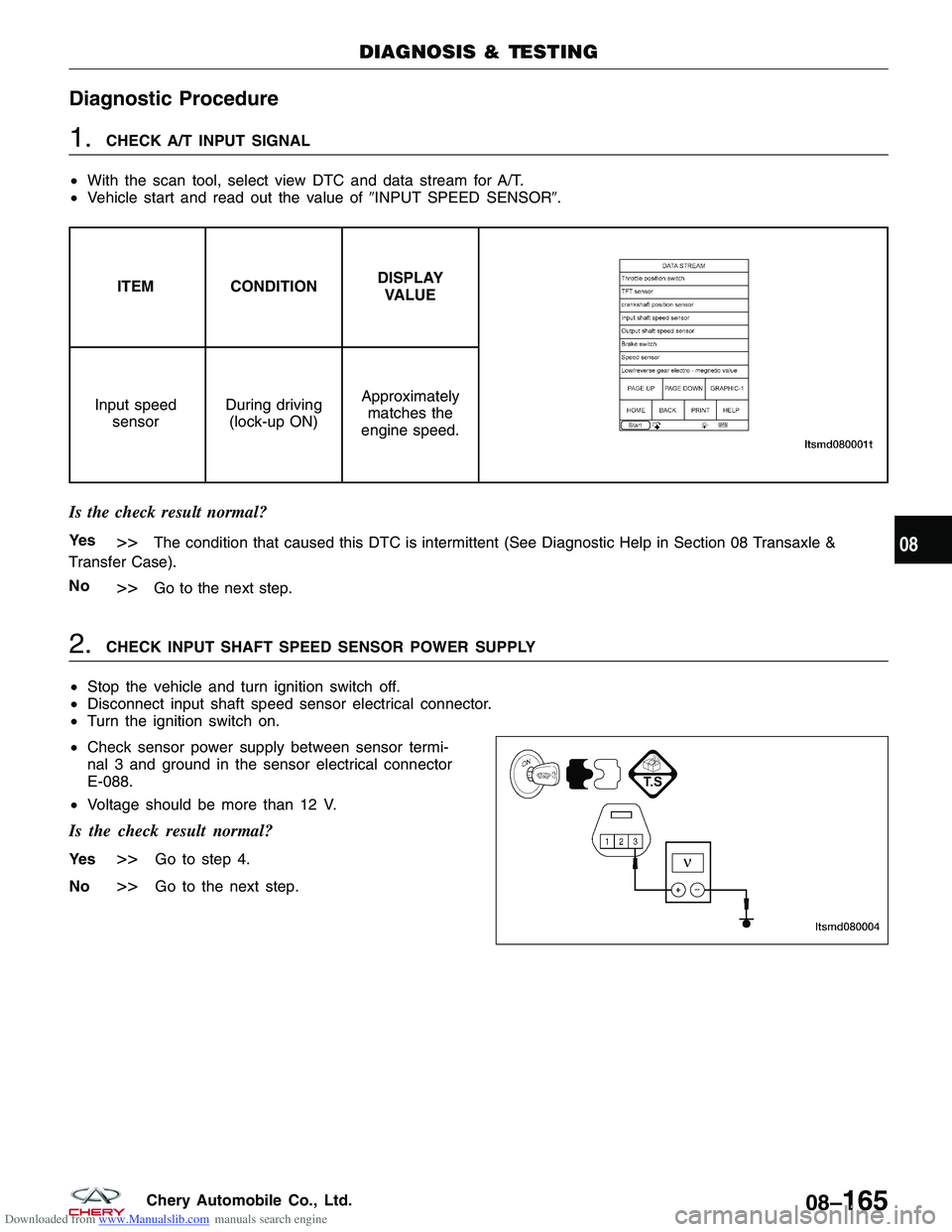
2.CHECK INPUT SHAFT SPEED SENSOR POWER SUPPLY
• Stop the vehicle and turn ignition switch off.
• Disconnect input shaft speed sensor electrical connector.
• Turn the ignition switch on.
• Check sensor power supply between sensor termi-
nal 3 and ground in the sensor electrical connector
E-088.
• Voltage should be more than 12 V.
Is the check result normal?
Ye s>>Go to step 4.
No
>>Go to the next step.
DIAGNOSIS & TESTING
LTSMD080004
08
08–165Chery Automobile Co., Ltd.
Page 1113 of 1903
Downloaded from www.Manualslib.com manuals search engine Diagnostic Procedure
1.CHECK A/T OUTPUT SIGNAL
• With the scan tool, select view DTC and data stream for A/T.
• Vehicle start and read out the value of �OUTPUT SPEED SENSOR�.
ITEM CONDITIONDISPLAY
VALUE
Output speed sensor During driving Approximately
matches the
speedometer reading.
Is the check result normal?
Ye s>>The condition that caused this DTC is intermittent (See Diagnostic Help in Section 08 Transaxle &
Transfer Case).
No
>>Go to the next step.
2.CHECK OUTPUT SHAFT SPEED SENSOR POWER SUPPLY
• Stop vehicle and turn ignition switch off.
• Disconnect output shaft speed sensor connector.
• Turn ignition switch on.
• Check sensor power supply between sensor termi-
nal 3 and ground in the sensor electrical connector
E-089.
• Voltage should be more than 12 V.
Is the check result normal?
Ye s>>Go to step 4.
No
>>Go to the next step.
DIAGNOSIS & TESTING
LTSMD080006
08–170Chery Automobile Co., Ltd.
Page 1118 of 1903
Downloaded from www.Manualslib.com manuals search engine On Board Diagnostic Logic
•Self-diagnosis detection logic.
DTC NO. DTC DEFINITION DTC DETECTION
CONDITION DTC SET
CONDITION POSSIBLE CAUSES
26 Brake pedal position
switch circuitmalfunction Vehicle is driving The brake switch is
on while vehicle is driving •
Brake switch
• Harness or
connectors (The
sensor circuit is open
or shorted)
• TCM
DTC Confirmation Procedure:
Before performing the following procedure, confirm that battery voltage is more than 12 V.
• Connect the X-431 scan tool to the Data Link Connector (DLC) - use the most current software available.
• After connection, press POWER key to start X-431.
• Turn ignition switch on, with the scan tool, view and erase stored DTCs in the TCM.
• Start engine then select �D�position.
• Drive the vehicle.
• With the scan tool, select view DTC and data stream.
• If the DTC is detected, the DTC condition is current. Go to Diagnostic Procedure - Step 1.
• If the DTC is not detected, the DTC condition is intermittent (See Diagnostic Help and Intermittent DTC Trou-
bleshooting in Section 08 Transaxle & Transfer Case for more information).
NOTE :
While performing electrical diagnosis & testing, always refer to the electrical schematics for specific circuit
and component information.
Diagnostic Procedure
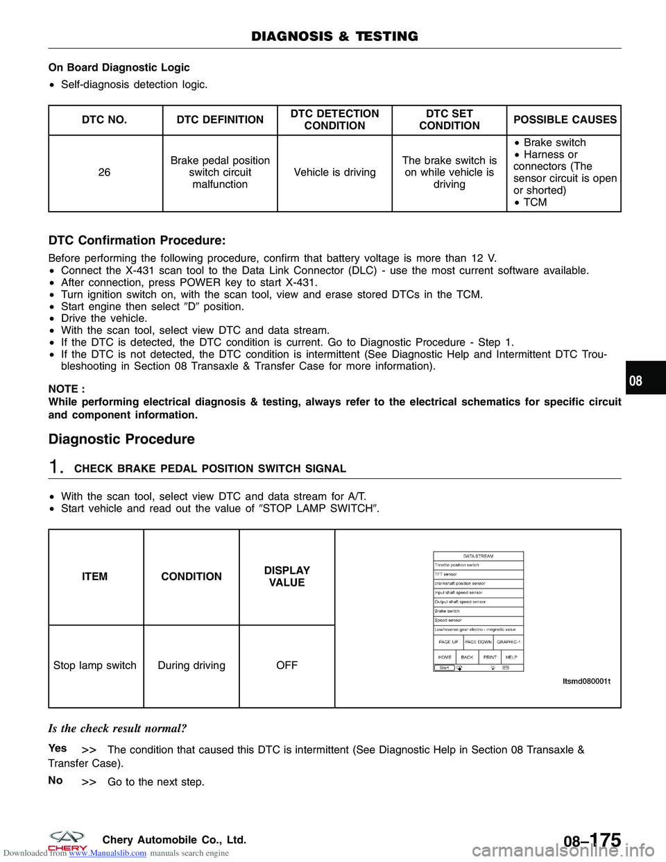
1.CHECK BRAKE PEDAL POSITION SWITCH SIGNAL
• With the scan tool, select view DTC and data stream for A/T.
• Start vehicle and read out the value of �STOP LAMP SWITCH�.
ITEM CONDITIONDISPLAY
VALUE
Stop lamp switch During driving OFF
Is the check result normal?
Ye s>>The condition that caused this DTC is intermittent (See Diagnostic Help in Section 08 Transaxle &
Transfer Case).
No
>>Go to the next step.
DIAGNOSIS & TESTING
08
08–175Chery Automobile Co., Ltd.
Page 1361 of 1903
Downloaded from www.Manualslib.com manuals search engine ON-VEHICLE SERVICE
Power Steering Filling and Flushing
Filling
1. Fill the power steering fluid reservoir to the proper level and let the fluid settle for at least two minutes.
2. Start the engine and let run for a few seconds, then turn the engine off.
3. Add fluid if necessary.
4. Repeat the above procedure until the fluid level remains constant after running the engine.
5. When the steering fluid temperature is relatively high, the steering fluid level will approach to the “MAX” level.
6. When the steering fluid cools down, the steering fluid level may approach to the “MIN” level.
NOTE :
If the steering fluid is extremely foamy or milky looking, allow the vehicle to stand a few minutes and repeat the
procedure.
Flushing
1. Raise and support the vehicle.
2. Remove the steering fluid reservoir release cap.
3. Siphon out the contaminated power steering fluid from the power steering liquid reservoir.
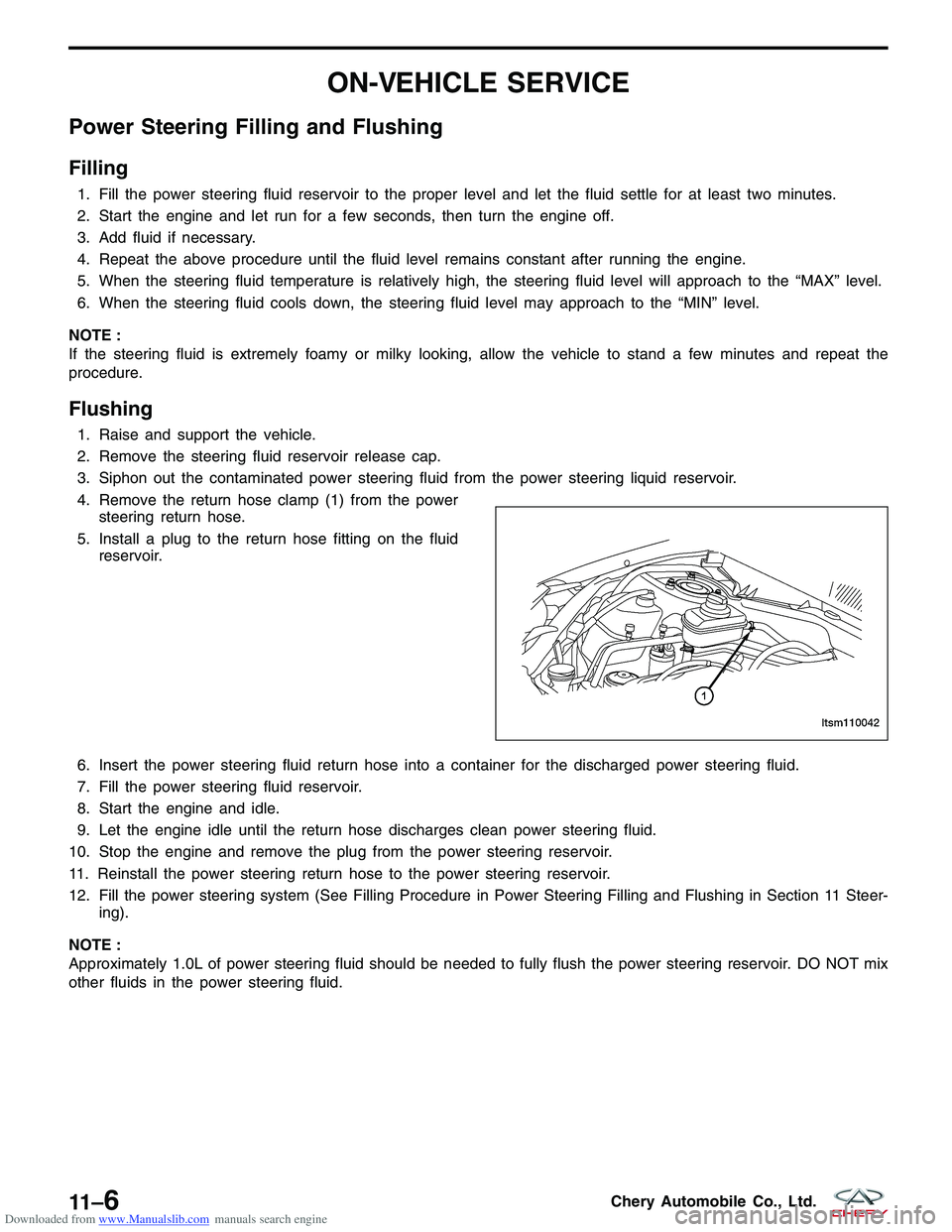
4. Remove the return hose clamp (1) from the power steering return hose.
5. Install a plug to the return hose fitting on the fluid reservoir.
6. Insert the power steering fluid return hose into a container for the discharged power steering fluid.
7. Fill the power steering fluid reservoir.
8. Start the engine and idle.
9. Let the engine idle until the return hose discharges clean power steering fluid.
10. Stop the engine and remove the plug from the power steering reservoir.
11. Reinstall the power steering return hose to the power steering reservoir.
12. Fill the power steering system (See Filling Procedure in Power Steering Filling and Flushing in Section 11 Steer- ing).
NOTE :
Approximately 1.0L of power steering fluid should be needed to fully flush the power steering reservoir. DO NOT mix
other fluids in the power steering fluid.
LTSM110042
11 –6Chery Automobile Co., Ltd.
Page 1362 of 1903
Downloaded from www.Manualslib.com manuals search engine Inspection
1. If the power steering fluid level is low, inspect the entire power steering system for potential leaks.
CAUTION:
DO NOT operate the vehicle with foamy steering fluid for an extended period. This may cause
pump damage.
2. Perform the following to inspect the power steering fluid reservoir level:•Park the vehicle on a level surface.
• Start the engine.
• Turn the steering wheel several times to heat the power steering fluid to 50°- 60°C.
• With the engine running, turn the steering wheel left and right to the wheel stops and repeat this several
times.
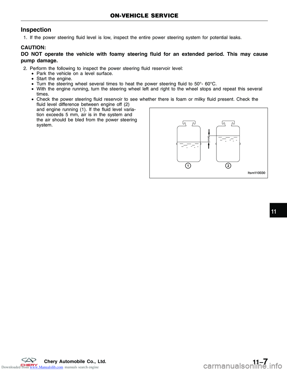
• Check the power steering fluid reservoir to see whether there is foam or milky fluid present. Check the
fluid level difference between engine off (2)
and engine running (1). If the fluid level varia-
tion exceeds 5 mm, air is in the system and
the air should be bled from the power steering
system.
ON-VEHICLE SERVICE
LTSM110030
11
11 –7Chery Automobile Co., Ltd.
Page 1376 of 1903
Downloaded from www.Manualslib.com manuals search engine ON-VEHICLE SERVICE
Steering Gear - LHD
Removal & Installation
NOTE :
The following special tools are required to perform the repair procedure:
•CH-10002 - Ball Joint Separator
1. Siphon out as much power steering fluid as possible from the reservoir.
WARNING!
Prolonged and repeated contact with power steering fluid will damage skin. If steering fluid is spilled on your
skin, wash it off immediately with water.
2. Remove the wheel mounting nuts and wheel assemblies from both sides of the vehicle. (Tighten: Wheel mounting nuts to 110 N·m)
3. Remove the return hose clamp (1) from the steer- ing liquid reservoir and insert the end of the hose
into a container.
4. Start the engine and turn the steering wheel from lock-to-lock until all power steering fluid has been drained from the system.
5. Stop the engine.
6. Raise and support the vehicle.
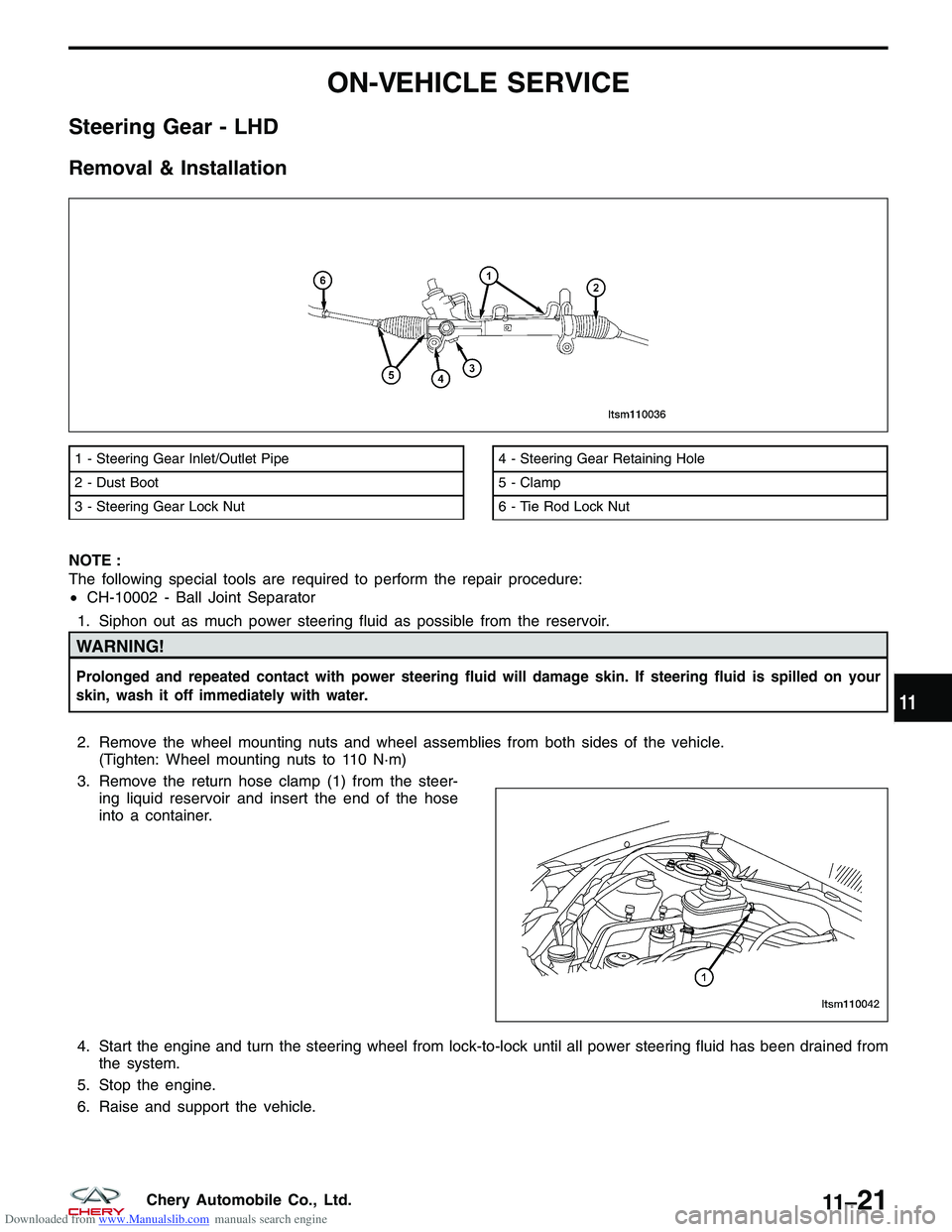
1 - Steering Gear Inlet/Outlet Pipe
2 - Dust Boot
3 - Steering Gear Lock Nut4 - Steering Gear Retaining Hole
5 - Clamp
6 - Tie Rod Lock Nut
LTSM110036
LTSM110042
11
11 –21Chery Automobile Co., Ltd.