Page 1586 of 1903

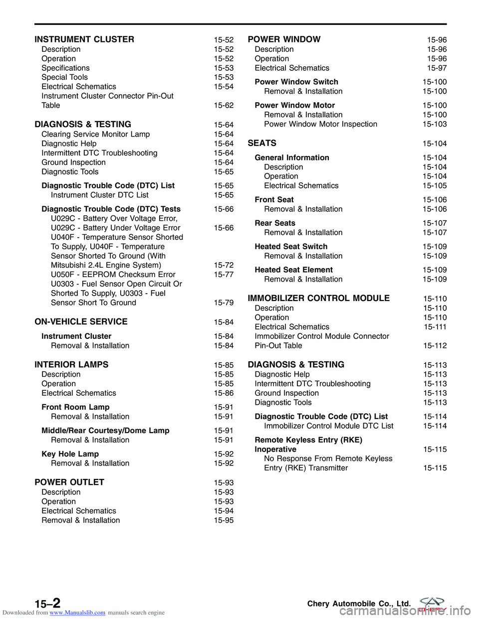
Downloaded from www.Manualslib.com manuals search engine INSTRUMENT CLUSTER15-52
Description 15-52
Operation 15-52
Specifications 15-53
Special Tools 15-53
Electrical Schematics 15-54
Instrument Cluster Connector Pin-Out
Table 15-62
DIAGNOSIS & TESTING15-64
Clearing Service Monitor Lamp 15-64
Diagnostic Help 15-64
Intermittent DTC Troubleshooting 15-64
Ground Inspection 15-64
Diagnostic Tools 15-65
Diagnostic Trouble Code (DTC) List 15-65
Instrument Cluster DTC List 15-65
Diagnostic Trouble Code (DTC) Tests 15-66
U029C - Battery Over Voltage Error,
U029C - Battery Under Voltage Error 15-66
U040F - Temperature Sensor Shorted
To Supply, U040F - Temperature
Sensor Shorted To Ground (With
Mitsubishi 2.4L Engine System) 15-72
U050F - EEPROM Checksum Error 15-77
U0303 - Fuel Sensor Open Circuit Or
Shorted To Supply, U0303 - Fuel
Sensor Short To Ground 15-79
ON-VEHICLE SERVICE15-84
Instrument Cluster 15-84
Removal & Installation 15-84
INTERIOR LAMPS15-85
Description 15-85
Operation 15-85
Electrical Schematics 15-86
Front Room Lamp 15-91
Removal & Installation 15-91
Middle/Rear Courtesy/Dome Lamp 15-91
Removal & Installation 15-91
Key Hole Lamp 15-92
Removal & Installation 15-92
POWER OUTLET15-93
Description 15-93
Operation 15-93
Electrical Schematics 15-94
Removal & Installation 15-95
POWER WINDOW15-96
Description 15-96
Operation 15-96
Electrical Schematics 15-97
Power Window Switch 15-100
Removal & Installation 15-100
Power Window Motor 15-100
Removal & Installation 15-100
Power Window Motor Inspection 15-103
SEATS15-104
General Information 15-104
Description 15-104
Operation 15-104
Electrical Schematics 15-105
Front Seat 15-106
Removal & Installation 15-106
Rear Seats 15-107
Removal & Installation 15-107
Heated Seat Switch 15-109
Removal & Installation 15-109
Heated Seat Element 15-109
Removal & Installation 15-109
IMMOBILIZER CONTROL MODULE15-110
Description 15-110
Operation 15-110
Electrical Schematics 15-111
Immobilizer Control Module Connector
Pin-Out Table 15-112
DIAGNOSIS & TESTING15-113
Diagnostic Help 15-113
Intermittent DTC Troubleshooting 15-113
Ground Inspection 15-113
Diagnostic Tools 15-113
Diagnostic Trouble Code (DTC) List 15-114
Immobilizer Control Module DTC List 15-114
Remote Keyless Entry (RKE)
Inoperative 15-115
No Response From Remote Keyless
Entry (RKE) Transmitter 15-115
15–2Chery Automobile Co., Ltd.
Page 1587 of 1903
Downloaded from www.Manualslib.com manuals search engine Diagnostic Trouble Code (DTC) Tests15-117
B1000 - ECU Defect: Internal Errors 15-117
B3042 - W-Line Short Circuit To
Ground, B3043 - W-Line Short Circuit
To Battery 15-121
B3050 - Relay External Line Short
Circuit To Ground Or Open Circuit,
Relay External Line Malfunction,
B3053 - Relay External Line Short
Circuit To Battery 15-126B3055 - No Transponder Modulation Or
No Transponder, B3056 - No
Transponder Fixed Code Programmed 15-132
B3060 - Unprogrammed Transponder
Fixed Code Received, B3061 -
Disturbed Or No Challenge/Response
Transponder Communication, B3077 -
Read-Only Transponder Detected
15-138
ON-VEHICLE SERVICE15-144
Immobilizer Control Module 15-144
Removal & Installation 15-144
BODY AND ACCESSORIES - BODY INTERIOR
15
15–3Chery Automobile Co., Ltd.
Page 1698 of 1903
Downloaded from www.Manualslib.com manuals search engine Diagnostic Trouble Code (DTC) List
Immobilizer Control Module DTC List
DTCDTC DEFINITION
B1000 ECU Defect, Internal Errors
B3040 Communication Error On W-Line, ECM Doesn’t Answer On Challenge Or Response
Requests
B3042 W-Line Short Circuit To Ground
B3043 W-Line Short Circuit To Battery
B3045 DWA Line Short Circuit To Ground Or Open Circuit, DWA Line Malfunction
B3048 DWA Line Short Circuit To Battery
B3050 Relay Extern Line Short Circuit To Ground Or Open Circuit, Relay Extern Line
Malfunction
B3053 Relay Extern Line Short Circuit To Battery
B3055 No Transponder Modulation Or No Transponder
B3056 No Transponder Fix Code Programmed
B3057 No Security Code Programmed
B3060 Unprogrammed Transponder Fix Code Received
B3061 Disturbed Or No Challenge / Response Transponder Communication
B3077 Read-Only Transponder Detected
DIAGNOSIS & TESTING
15–11 4Chery Automobile Co., Ltd.
Page 1699 of 1903

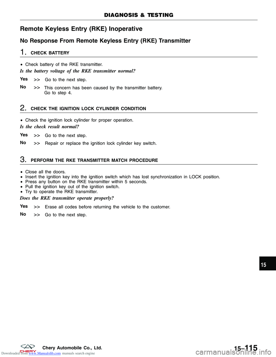
Downloaded from www.Manualslib.com manuals search engine Remote Keyless Entry (RKE) Inoperative
No Response From Remote Keyless Entry (RKE) Transmitter
1.CHECK BATTERY
• Check battery of the RKE transmitter.
Is the battery voltage of the RKE transmitter normal?
Ye s>>Go to the next step.
No
>>This concern has been caused by the transmitter battery.
Go to step 4.
2.CHECK THE IGNITION LOCK CYLINDER CONDITION
• Check the ignition lock cylinder for proper operation.
Is the check result normal?
Ye s>>Go to the next step.
No
>>Repair or replace the ignition lock cylinder key switch.
3.PERFORM THE RKE TRANSMITTER MATCH PROCEDURE
• Close all the doors.
• Insert the ignition key into the ignition switch which has lost synchronization in LOCK position.
• Press any button on the RKE transmitter within 5 seconds.
• Pull the ignition key out of the ignition switch.
• Try to operate the RKE transmitter.
Does the RKE transmitter operate properly?
Ye s>>Erase all codes before returning the vehicle to the customer.
No
>>Go to the next step.
DIAGNOSIS & TESTING
15
15–11 5Chery Automobile Co., Ltd.
Page 1722 of 1903
Downloaded from www.Manualslib.com manuals search engine B3060 - Unprogrammed Transponder Fixed Code Received
B3061 - Disturbed Or No Challenge/Response Transponder Communication
B3077 - Read-Only Transponder Detected
DIAGNOSIS & TESTING
LTSMW150081T
15–138Chery Automobile Co., Ltd.
Page 1723 of 1903

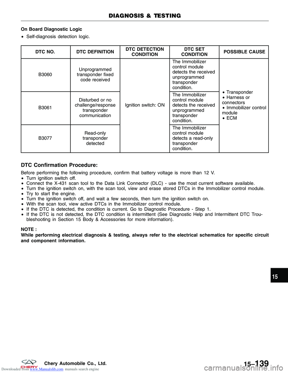
Downloaded from www.Manualslib.com manuals search engine On Board Diagnostic Logic
•Self-diagnosis detection logic.
DTC NO. DTC DEFINITION DTC DETECTION
CONDITION DTC SET
CONDITION POSSIBLE CAUSE
B3060 Unprogrammed
transponder fixed code received
Ignition switch: ON The Immobilizer
control module
detects the received
unprogrammed
transponder
condition.
•Transponder
• Harness or
connectors
• Immobilizer control
module
• ECM
B3061
Disturbed or no
challenge/response transponder
communication The Immobilizer
control module
detects the received
unprogrammed
transponder
condition.
B3077 Read-only
transponder detected The Immobilizer
control module
detects a read-only
transponder
condition.
DTC Confirmation Procedure:
Before performing the following procedure, confirm that battery voltage is more than 12 V.
•
Turn ignition switch off.
• Connect the X-431 scan tool to the Data Link Connector (DLC) - use the most current software available.
• Turn the ignition switch on, with the scan tool, view and erase stored DTCs in the Immobilizer control module.
• Try to start the engine.
• Turn the ignition switch off, and wait a few seconds, then turn the ignition switch on.
• With the scan tool, view active DTCs in the Immobilizer control module.
• If the DTC is detected, the condition is current. Go to Diagnostic Procedure - Step 1.
• If the DTC is not detected, the DTC condition is intermittent (See Diagnostic Help and Intermittent DTC Trou-
bleshooting in Section 15 Body & Accessories for more information).
NOTE :
While performing electrical diagnosis & testing, always refer to the electrical schematics for specific circuit
and component information.
DIAGNOSIS & TESTING
15
15–139Chery Automobile Co., Ltd.
Page 1762 of 1903

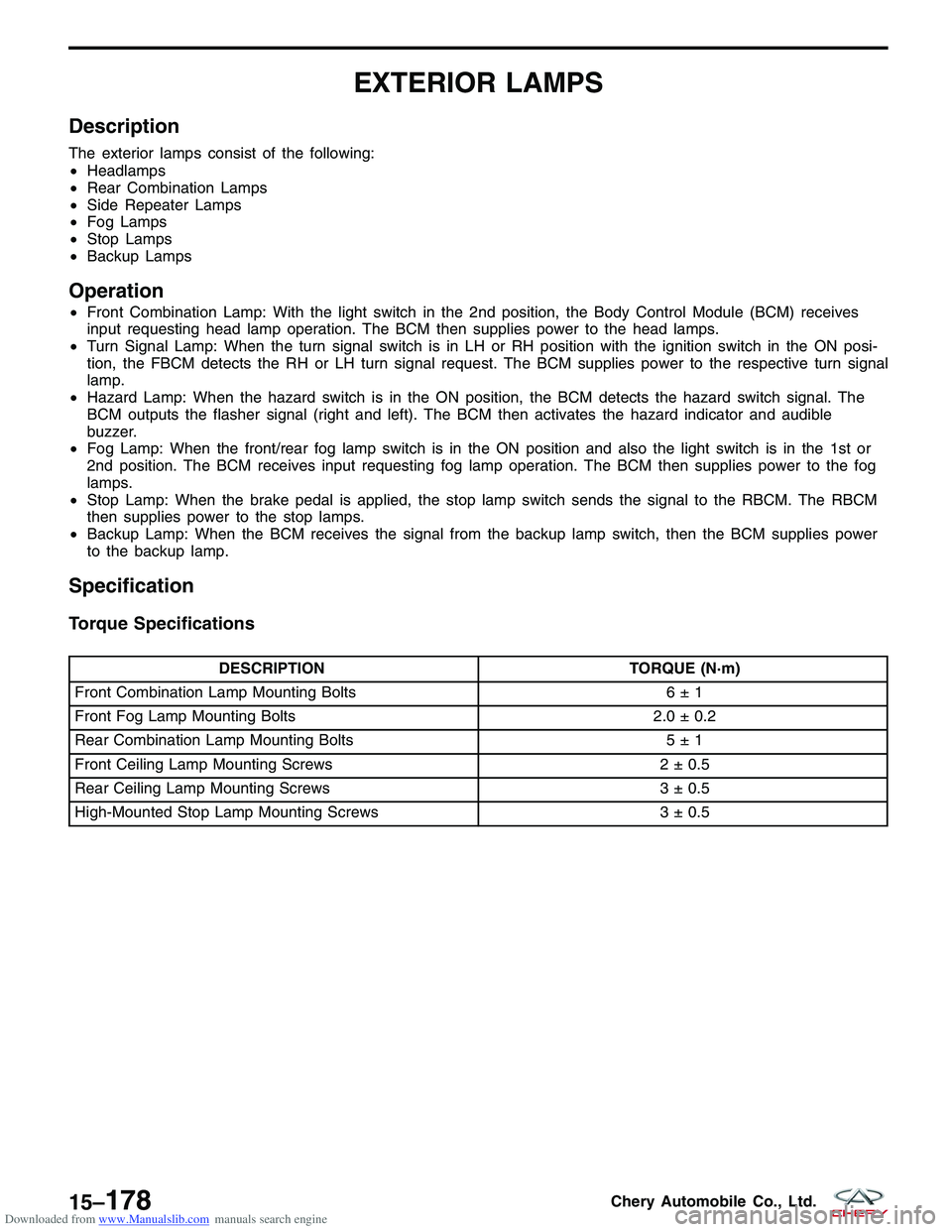
Downloaded from www.Manualslib.com manuals search engine EXTERIOR LAMPS
Description
The exterior lamps consist of the following:
•Headlamps
• Rear Combination Lamps
• Side Repeater Lamps
• Fog Lamps
• Stop Lamps
• Backup Lamps
Operation
•Front Combination Lamp: With the light switch in the 2nd position, the Body Control Module (BCM) receives
input requesting head lamp operation. The BCM then supplies power to the head lamps.
• Turn Signal Lamp: When the turn signal switch is in LH or RH position with the ignition switch in the ON posi-
tion, the FBCM detects the RH or LH turn signal request. The BCM supplies power to the respective turn signal
lamp.
• Hazard Lamp: When the hazard switch is in the ON position, the BCM detects the hazard switch signal. The
BCM outputs the flasher signal (right and left). The BCM then activates the hazard indicator and audible
buzzer.
• Fog Lamp: When the front/rear fog lamp switch is in the ON position and also the light switch is in the 1st or
2nd position. The BCM receives input requesting fog lamp operation. The BCM then supplies power to the fog
lamps.
• Stop Lamp: When the brake pedal is applied, the stop lamp switch sends the signal to the RBCM. The RBCM
then supplies power to the stop lamps.
• Backup Lamp: When the BCM receives the signal from the backup lamp switch, then the BCM supplies power
to the backup lamp.
Specification
Torque Specifications
DESCRIPTION TORQUE (N·m)
Front Combination Lamp Mounting Bolts 6 ± 1
Front Fog Lamp Mounting Bolts 2.0 ± 0.2
Rear Combination Lamp Mounting Bolts 5 ± 1
Front Ceiling Lamp Mounting Screws 2 ± 0.5
Rear Ceiling Lamp Mounting Screws 3 ± 0.5
High-Mounted Stop Lamp Mounting Screws 3 ± 0.5
15–178Chery Automobile Co., Ltd.
Page 1793 of 1903
Downloaded from www.Manualslib.com manuals search engine MIRRORS
Description
The mirrors are controlled by a single switch assembly located on the driver’s door trim panel. A three-position switch
selects the right or left power mirror for adjustment. A momentary joystick directional switch allows the driver to adjust
the selected power mirror in the Up & Down or Right & Left directions. The heated mirror system is controlled by the
Body Control Module (BCM). When there is water vapor on the mirrors, the heated mirrors will eliminate the water
vapor.
Operation
Use the mirror select switch, located on the driver’s door trim panel to adjust the view obtained in the outside mirrors.
Rotate the joystick for Left or Right mirror selection. Select a mirror and press the joystick that correspond with the
direction that you want the mirror to move.
15
15–209Chery Automobile Co., Ltd.