2009 CHERY TIGGO ESP
[x] Cancel search: ESPPage 712 of 1903

Downloaded from www.Manualslib.com manuals search engine 6. Installation is in the reverse order of removal.
NOTE :
After installing the engine coolant temperature sensor, check the coolant level.
Knock Sensor
Description
The knock sensor is attached to the cylinder block. The knock sensor is designed to detect engine vibration that is
caused by detonation.
Operation
When the knock sensor detects a knock in one of the cylinders, it sends an input signal to the Engine Control Module
(ECM). In response, the ECM retards ignition timing for all cylinders by a specified amount.
The knock sensor contains a piezoelectric material which constantly vibrates and sends an input voltage (signal) to
the ECM while the engine operates. As the intensity of the vibration increases, the knock sensor output voltage also
increases.
The ECM ignores knock sensor input during engine idle conditions. Once the engine speed exceeds a specified
value, knock retard is allowed.
Removal & Installation
1. Disconnect and isolate the negative battery cable.
2. Disconnect the knock sensor electrical connector.
3. Remove the knock sensor retaining bolt (1) and
remove the knock sensor.
(Tighten: Knock sensor retaining bolt to 20 N·m)
4. Installation is in the reverse order of removal.
Oxygen Sensor
Description
This vehicle is equipped with two oxygen sensors (upstream oxygen sensor & downstream oxygen sensor). The oxy-
gen sensors are located before and after the three way catalyst. The oxygen sensors continually monitor the oxygen
level in the exhaust gas. The sensor is made of ceramic zirconia. The zirconia generates voltage from approximately
1 volt in richer conditions to 0 volt in leaner conditions.
Operation
The O2 sensors produce voltages from 0 to 1 volt, depending upon the oxygen content of the exhaust gas. When a
large amount of oxygen is present (caused by a lean air/fuel mixture, can be caused by misfire and exhaust leaks),
the sensors produces a low voltage. When there is a lesser amount of oxygen present (caused by a rich air/fuel
mixture, can be caused by internal engine problems) it produces a higher voltage. By monitoring the oxygen content
and converting it to electrical voltage, the sensors act as a rich-lean switch.
The oxygen sensors are equipped with a heating element that keeps the sensors at proper operating temperature
during all operating modes. Maintaining correct sensor temperature at all times allows the system to enter into closed
loop operation sooner. Also, it allows the system to remain in closed loop operation during periods of extended idle.
ON-VEHICLE SERVICE
BESM030018
03–428Chery Automobile Co., Ltd.
Page 817 of 1903

Downloaded from www.Manualslib.com manuals search engine 4. Installation is in the reverse order of removal.
CAUTION:
Before removing the coolant temperature sensor (for instrument cluster), release the coolant pres-
sure and make sure the engine is cold.
Knock Sensor
Description
The knock sensor is attached to the cylinder block. The knock sensor is designed to detect engine vibration that is
caused by detonation.
Operation
When the knock sensor detects a knock in one of the cylinders, it sends an input signal to the ECM. In response, the
ECM retards ignition timing for all cylinders by a scheduled amount.
Knock sensors contain a piezoelectric material which constantly vibrates and sends an input voltage (signal) to the
ECM while the engine operates. As the intensity of the vibration increases, the knock sensor output voltage also
increases.
The voltage signal produced by the knock sensor increases with the amplitude of vibration. The ECM receives an
input knock sensor voltage signal. If the signal rises above a predetermined level, the ECM will store that value in
memory and retard ignition timing to reduce engine knock. If the knock sensor voltage exceeds a present value, the
ECM retards ignition timing for all cylinders. It is not a selective cylinder retard.
The ECM ignores knock sensor input signal during engine idle conditions. Once the engine speed exceeds a spec-
ified value, knock retard is allowed.
Removal & Installation
1. Disconnect and isolate the negative battery cable.
2. Disconnect the knock sensor electrical connector.
3. Remove the knock sensor retaining bolt (1) andremove the knock sensor.
(Tighten: Knock sensor retaining bolt to 20 N·m).
4. Installation is in the reverse order of removal.
Oxygen Sensor
Description
This vehicle is equipped with two oxygen sensors (upstream oxygen sensor & downstream oxygen sensor). The oxy-
gen sensors are located before and after the three way catalyst. The oxygen sensors continually monitor the oxygen
level in the exhaust gas. The sensor is made of ceramic zirconia. The zirconia generates voltage from approximately
1 volt in richer conditions to 0 volt in leaner conditions.
Operation
The O2 sensors produce voltages from 0 to 1 volt, depending upon the oxygen content of the exhaust gas. When a
large amount of oxygen is present (caused by a lean air/fuel mixture, can be caused by misfire and exhaust leaks),
the sensors produces a low voltage. When there is a lesser amount of oxygen present (caused by a rich air/fuel
mixture, can be caused by internal engine problems) it produces a higher voltage. By monitoring the oxygen content
and converting it to electrical voltage, the sensors act as a rich-lean switch.
ON-VEHICLE SERVICE
LTSM030011
03
03–533Chery Automobile Co., Ltd.
Page 939 of 1903

Downloaded from www.Manualslib.com manuals search engine WARNING!
Exhaust gases contain carbon monoxide which can be harmful to your health and are potentially lethal. Exhaust
system leaks should be repaired immediately. Never operate the engine in enclosed areas. Failure to follow
these instructions may result in personal injury or death.
Operation
In order to reduce vehicle emissions released by the engine, the catalytic converter is required to perform in all oper-
ating conditions. This reduction is especially beneficial during the cold start and warm up phases of operation, which
is when a majority of the tailpipe emissions occur on today’s vehicles because the catalytic converter has not yet
reached its operating temperature. The exhaust system channels exhaust gases from the engine and away from the
vehicle.
Specifications
Torque Specifications
DESCRIPTIONTORQUE (N·m)
Catalytic Converter Mounting Nuts 50
Exhaust Manifold Flange Bolts 49 ± 5
Muffler Mounting Nuts 50
GENERAL INFORMATION
07
07–3Chery Automobile Co., Ltd.
Page 949 of 1903

Downloaded from www.Manualslib.com manuals search engine Operation
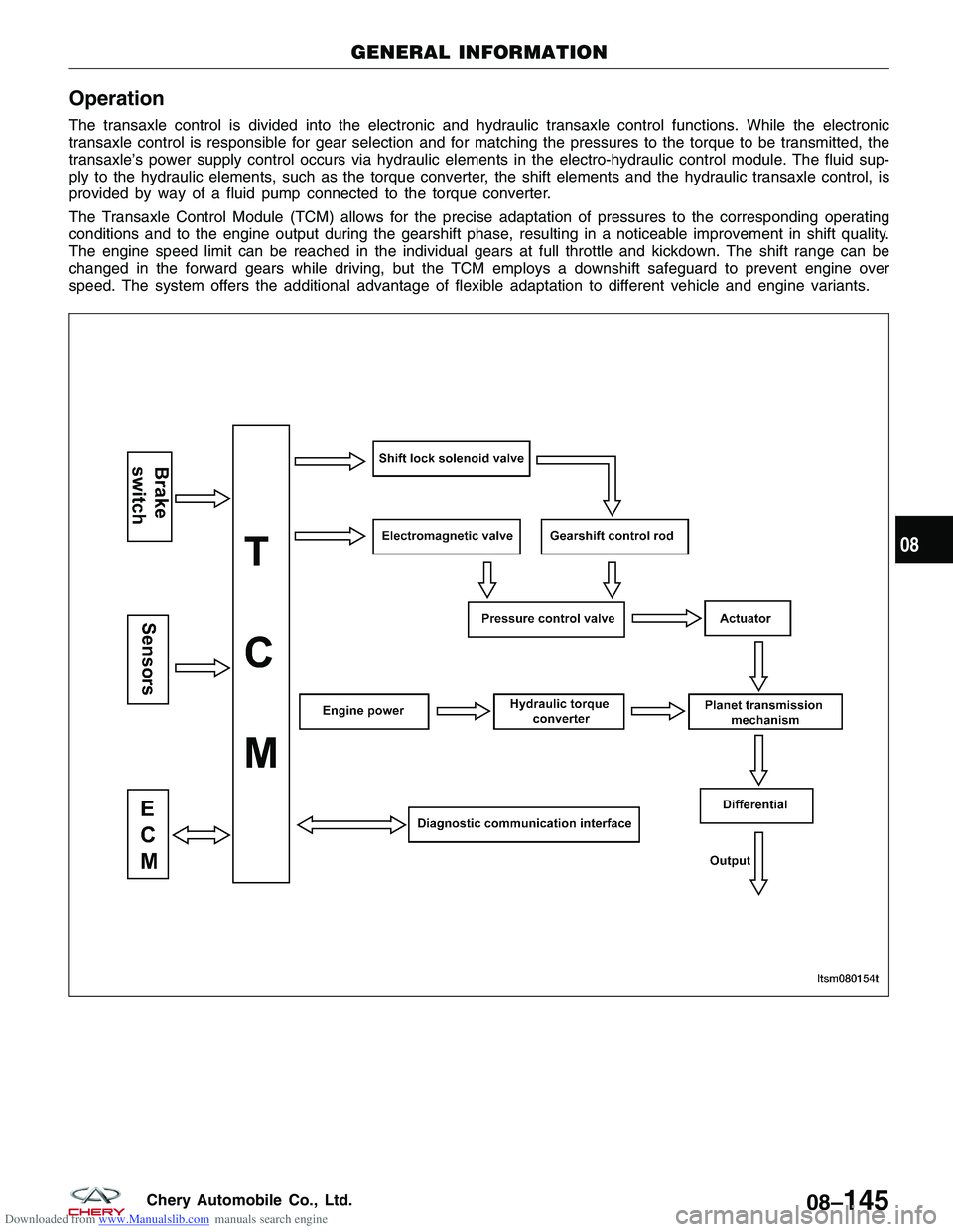
Automatic transaxle control is divided into the electronic and hydraulic transaxle control functions. While the elec-
tronic transaxle control is responsible for gear selection and for matching the pressures to the torque to be trans-
mitted, the transaxle’s power supply control occurs via hydraulic elements in the electro-hydraulic control module. The
fluid supply to the hydraulic elements, such as the torque converter, the shift elements and the hydraulic transaxle
control, is provided by way of a fluid pump connected to the torque converter.
The Transaxle Control Module (TCM) allows for the precise adaptation of pressures to the corresponding operating
conditions and to the engine output during the gearshift phase, resulting in a noticeable improvement in shift quality.
The engine speed limit can be reached in the individual gears at full throttle and kickdown. The shift range can be
changed in the forward gears while driving, but the TCM employs a downshift safeguard to prevent engine over
speed. The system offers the additional advantage of flexible adaptation to different vehicle and engine variants.
GENERAL INFORMATION
LTSM080154T
08–6Chery Automobile Co., Ltd.
Page 1088 of 1903

Downloaded from www.Manualslib.com manuals search engine Operation
The transaxle control is divided into the electronic and hydraulic transaxle control functions. While the electronic
transaxle control is responsible for gear selection and for matching the pressures to the torque to be transmitted, the
transaxle’s power supply control occurs via hydraulic elements in the electro-hydraulic control module. The fluid sup-
ply to the hydraulic elements, such as the torque converter, the shift elements and the hydraulic transaxle control, is
provided by way of a fluid pump connected to the torque converter.
The Transaxle Control Module (TCM) allows for the precise adaptation of pressures to the corresponding operating
conditions and to the engine output during the gearshift phase, resulting in a noticeable improvement in shift quality.
The engine speed limit can be reached in the individual gears at full throttle and kickdown. The shift range can be
changed in the forward gears while driving, but the TCM employs a downshift safeguard to prevent engine over
speed. The system offers the additional advantage of flexible adaptation to different vehicle and engine variants.
GENERAL INFORMATION
LTSM080154T
08
08–145Chery Automobile Co., Ltd.
Page 1211 of 1903

Downloaded from www.Manualslib.com manuals search engine Assembly
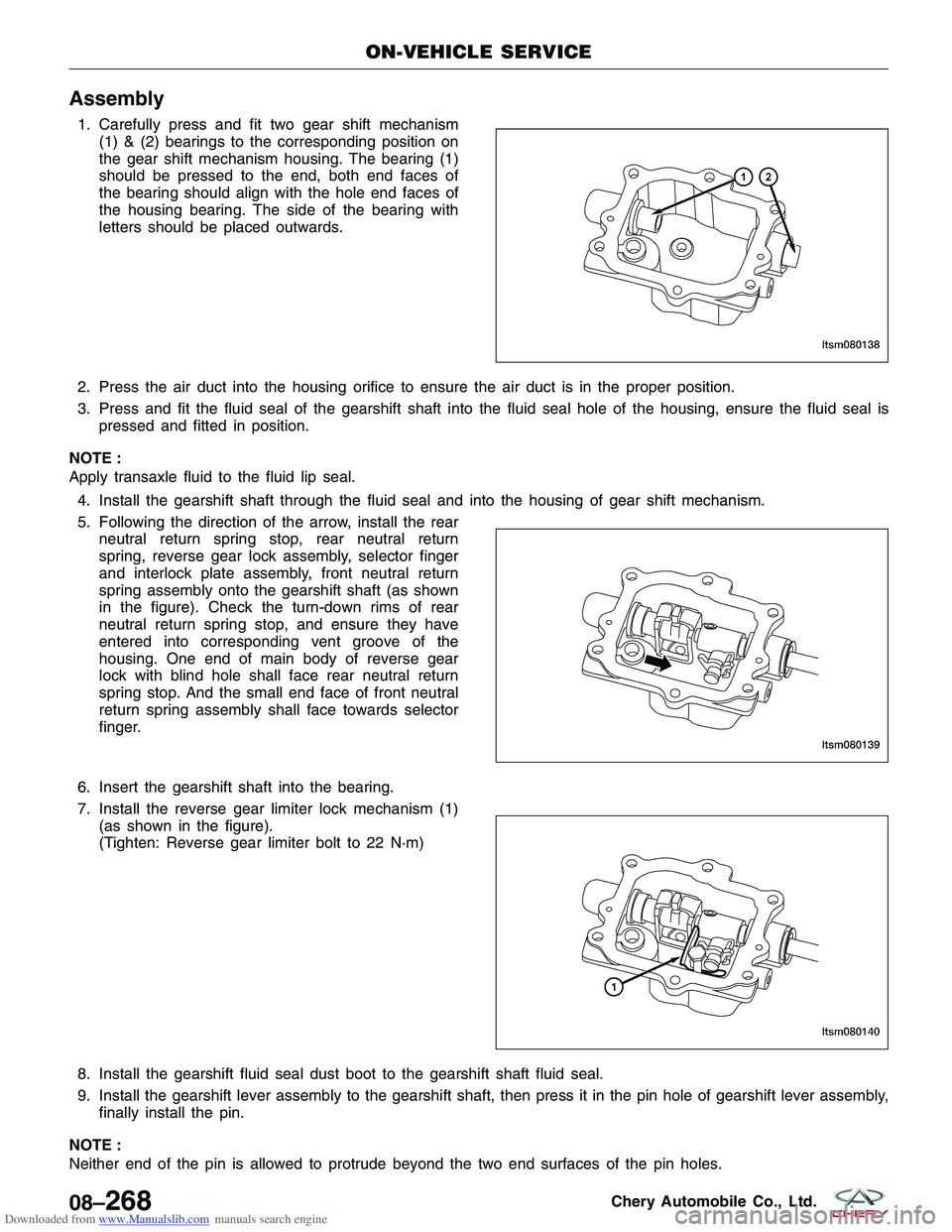
1. Carefully press and fit two gear shift mechanism(1) & (2) bearings to the corresponding position on
the gear shift mechanism housing. The bearing (1)
should be pressed to the end, both end faces of
the bearing should align with the hole end faces of
the housing bearing. The side of the bearing with
letters should be placed outwards.
2. Press the air duct into the housing orifice to ensure the air duct is in the proper position.
3. Press and fit the fluid seal of the gearshift shaft into the fluid seal hole of the housing, ensure the fluid seal is pressed and fitted in position.
NOTE :
Apply transaxle fluid to the fluid lip seal. 4. Install the gearshift shaft through the fluid seal and into the housing of gear shift mechanism.
5. Following the direction of the arrow, install the rear neutral return spring stop, rear neutral return
spring, reverse gear lock assembly, selector finger
and interlock plate assembly, front neutral return
spring assembly onto the gearshift shaft (as shown
in the figure). Check the turn-down rims of rear
neutral return spring stop, and ensure they have
entered into corresponding vent groove of the
housing. One end of main body of reverse gear
lock with blind hole shall face rear neutral return
spring stop. And the small end face of front neutral
return spring assembly shall face towards selector
finger.
6. Insert the gearshift shaft into the bearing.
7. Install the reverse gear limiter lock mechanism (1) (as shown in the figure).
(Tighten: Reverse gear limiter bolt to 22 N·m)
8. Install the gearshift fluid seal dust boot to the gearshift shaft fluid seal.
9. Install the gearshift lever assembly to the gearshift shaft, then press it in the pin hole of gearshift lever assembly, finally install the pin.
NOTE :
Neither end of the pin is allowed to protrude beyond the two end surfaces of the pin holes.
ON-VEHICLE SERVICE
LTSM080138
LTSM080139
LTSM080140
08–268Chery Automobile Co., Ltd.
Page 1212 of 1903

Downloaded from www.Manualslib.com manuals search engine 10. Align the selector finger (1) and fork shaft springpin (2), install the spring pin of selector finger (as
shown by the arrow in the figure).
11. Tighten the interlock plate limit bolt (1) together with the shim to the housing (as shown in the fig-
ure). The tightening torque of the bolt is 30 N·m.
Check front end circular cylinder of the bolt to
ensure it is in the corresponding groove of selector
finger.
12. Check the gearshift shaft to ensure it is able to rotate and perform axial movement freely.
13. Install air duct (1) and air duct cap (2). Apply seal- ant to the surface of the inserted part of air duct.
14. Install the backup light switch assembly (1). (Tighten: Backup light switch to 32 N·m)
ON-VEHICLE SERVICE
LTSM080094
LTSM080128
LTSM080134
LTSM080135
08
08–269Chery Automobile Co., Ltd.
Page 1260 of 1903

Downloaded from www.Manualslib.com manuals search engine GENERAL INFORMATION
Description
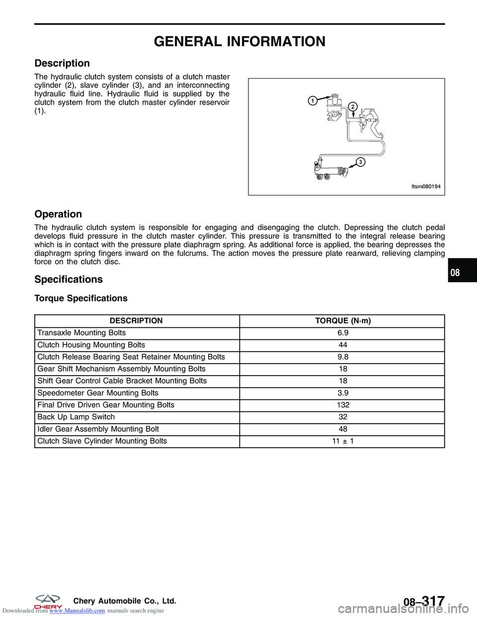
The hydraulic clutch system consists of a clutch master
cylinder (2), slave cylinder (3), and an interconnecting
hydraulic fluid line. Hydraulic fluid is supplied by the
clutch system from the clutch master cylinder reservoir
(1).
Operation
The hydraulic clutch system is responsible for engaging and disengaging the clutch. Depressing the clutch pedal
develops fluid pressure in the clutch master cylinder. This pressure is transmitted to the integral release bearing
which is in contact with the pressure plate diaphragm spring. As additional force is applied, the bearing depresses the
diaphragm spring fingers inward on the fulcrums. The action moves the pressure plate rearward, relieving clamping
force on the clutch disc.
Specifications
Torque Specifications
DESCRIPTIONTORQUE (N·m)
Transaxle Mounting Bolts 6.9
Clutch Housing Mounting Bolts 44
Clutch Release Bearing Seat Retainer Mounting Bolts 9.8
Gear Shift Mechanism Assembly Mounting Bolts 18
Shift Gear Control Cable Bracket Mounting Bolts 18
Speedometer Gear Mounting Bolts 3.9
Final Drive Driven Gear Mounting Bolts 132
Back Up Lamp Switch 32
Idler Gear Assembly Mounting Bolt 48
Clutch Slave Cylinder Mounting Bolts 11 ± 1
LTSM080194
08
08–317Chery Automobile Co., Ltd.