Page 1586 of 1903

Downloaded from www.Manualslib.com manuals search engine INSTRUMENT CLUSTER15-52
Description 15-52
Operation 15-52
Specifications 15-53
Special Tools 15-53
Electrical Schematics 15-54
Instrument Cluster Connector Pin-Out
Table 15-62
DIAGNOSIS & TESTING15-64
Clearing Service Monitor Lamp 15-64
Diagnostic Help 15-64
Intermittent DTC Troubleshooting 15-64
Ground Inspection 15-64
Diagnostic Tools 15-65
Diagnostic Trouble Code (DTC) List 15-65
Instrument Cluster DTC List 15-65
Diagnostic Trouble Code (DTC) Tests 15-66
U029C - Battery Over Voltage Error,
U029C - Battery Under Voltage Error 15-66
U040F - Temperature Sensor Shorted
To Supply, U040F - Temperature
Sensor Shorted To Ground (With
Mitsubishi 2.4L Engine System) 15-72
U050F - EEPROM Checksum Error 15-77
U0303 - Fuel Sensor Open Circuit Or
Shorted To Supply, U0303 - Fuel
Sensor Short To Ground 15-79
ON-VEHICLE SERVICE15-84
Instrument Cluster 15-84
Removal & Installation 15-84
INTERIOR LAMPS15-85
Description 15-85
Operation 15-85
Electrical Schematics 15-86
Front Room Lamp 15-91
Removal & Installation 15-91
Middle/Rear Courtesy/Dome Lamp 15-91
Removal & Installation 15-91
Key Hole Lamp 15-92
Removal & Installation 15-92
POWER OUTLET15-93
Description 15-93
Operation 15-93
Electrical Schematics 15-94
Removal & Installation 15-95
POWER WINDOW15-96
Description 15-96
Operation 15-96
Electrical Schematics 15-97
Power Window Switch 15-100
Removal & Installation 15-100
Power Window Motor 15-100
Removal & Installation 15-100
Power Window Motor Inspection 15-103
SEATS15-104
General Information 15-104
Description 15-104
Operation 15-104
Electrical Schematics 15-105
Front Seat 15-106
Removal & Installation 15-106
Rear Seats 15-107
Removal & Installation 15-107
Heated Seat Switch 15-109
Removal & Installation 15-109
Heated Seat Element 15-109
Removal & Installation 15-109
IMMOBILIZER CONTROL MODULE15-110
Description 15-110
Operation 15-110
Electrical Schematics 15-111
Immobilizer Control Module Connector
Pin-Out Table 15-112
DIAGNOSIS & TESTING15-113
Diagnostic Help 15-113
Intermittent DTC Troubleshooting 15-113
Ground Inspection 15-113
Diagnostic Tools 15-113
Diagnostic Trouble Code (DTC) List 15-114
Immobilizer Control Module DTC List 15-114
Remote Keyless Entry (RKE)
Inoperative 15-115
No Response From Remote Keyless
Entry (RKE) Transmitter 15-115
15–2Chery Automobile Co., Ltd.
Page 1588 of 1903
Downloaded from www.Manualslib.com manuals search engine AUDIO SYSTEM
Description
The audio system consists of the following components:
•Audio Unit
• Front Speakers
• Front Tweeters
• Rear Speakers
• Window Antenna (audio)
The audio system is standard factory-installed equipment. The system uses an ignition switched source of battery
current so that the system will operate when the ignition switch is in the LOCK/ACC/ON positions. The system will
also operate in the OFF position for one hour.
Operation
With the audio system on, radio signals are received by the window antenna, the audio unit then sends audio signals
to front speakers and rear speakers.
15–4Chery Automobile Co., Ltd.
Page 1619 of 1903
Downloaded from www.Manualslib.com manuals search engine Door Lock Switch
Removal & Installation
1. Turn the ignition switch off.
2. Remove the power window and door lock/unlockswitch bezel mounting screw (1).
3. Using a trim stick, pry out the power window and door lock/unlock switch assembly from the front door.
4. Disconnect the power window and door lock/unlock switch electrical connectors.
5. Remove the power window and door lock/unlock switch retaining screws to remove the power window and door lock/unlock switch.
6. Installation is in the reverse order of removal
Door Lock Assembly
Removal & Installation
NOTE :
The passenger door is shown, all other doors are similar.
1. Disconnect the negative battery cable.
2. Turn the ignition switch off.
3. Using a small trim stick, remove the pull handle cover (1) from the pull handle (2).
DOOR LOCKS
LTSM150097
LTSM150139
15
15–35Chery Automobile Co., Ltd.
Page 1620 of 1903
Downloaded from www.Manualslib.com manuals search engine 4. Remove the inner door handle mounting screw (1).
5. Remove the pull handle mounting screws (2).
6. Using a small trim stick, remove the inner doorhandle trim bezel (1).
7. Carefully pry the door trim panel clips from the door.
8. Disconnect the power window switch and the door lamp electrical connector.
9. Remove the door trim panel.
10. Disconnect the speaker connector (1).
11. Remove the inner door handle assembly mounting screw (2).
12. Disconnect the inner door handle cables (3).
13. Remove the protective film (4).
DOOR LOCKS
LTSM150134
LTSM150140
LTSM150135
15–36Chery Automobile Co., Ltd.
Page 1622 of 1903

Downloaded from www.Manualslib.com manuals search engine BODY CONTROL MODULE - BCM
Description
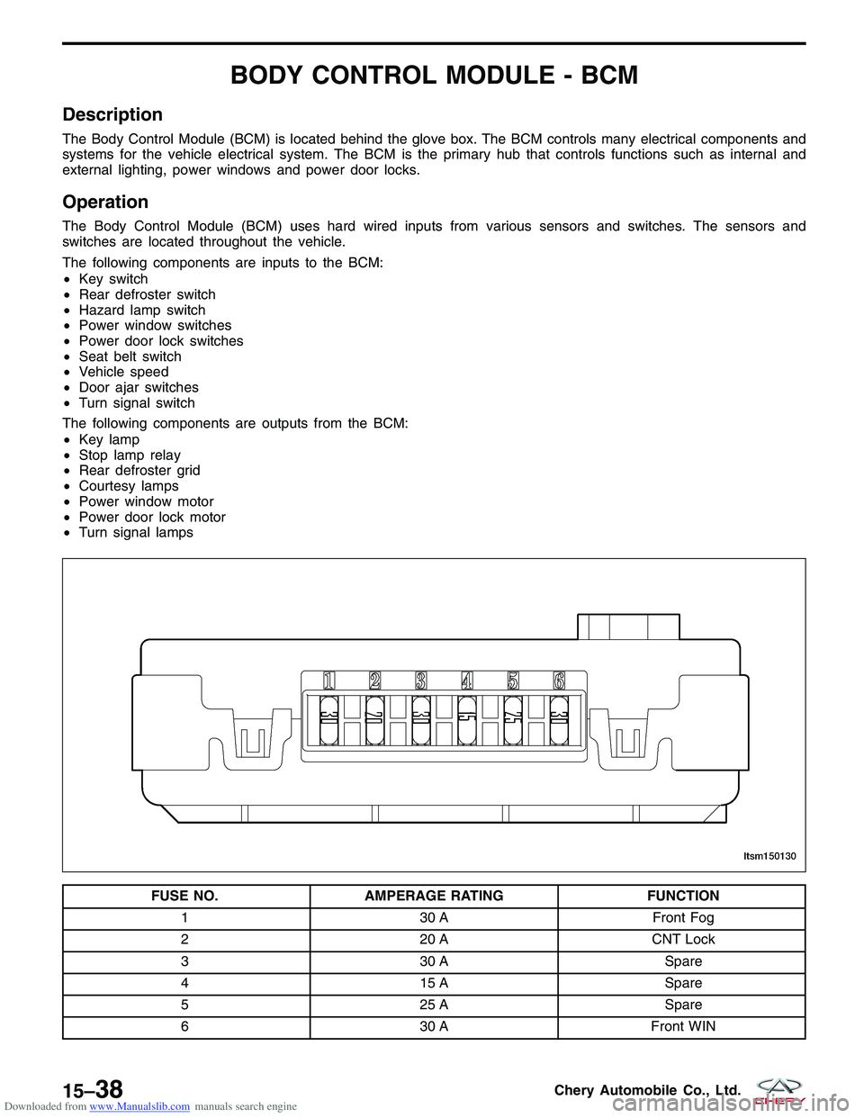
The Body Control Module (BCM) is located behind the glove box. The BCM controls many electrical components and
systems for the vehicle electrical system. The BCM is the primary hub that controls functions such as internal and
external lighting, power windows and power door locks.
Operation
The Body Control Module (BCM) uses hard wired inputs from various sensors and switches. The sensors and
switches are located throughout the vehicle.
The following components are inputs to the BCM:
•Key switch
• Rear defroster switch
• Hazard lamp switch
• Power window switches
• Power door lock switches
• Seat belt switch
• Vehicle speed
• Door ajar switches
• Turn signal switch
The following components are outputs from the BCM:
• Key lamp
• Stop lamp relay
• Rear defroster grid
• Courtesy lamps
• Power window motor
• Power door lock motor
• Turn signal lamps
FUSE NO. AMPERAGE RATING FUNCTION
1 30 AFront Fog
2 20 ACNT Lock
3 30 A Spare
4 15 A Spare
5 25 A Spare
6 30 AFront WIN
LTSM150130
15–38Chery Automobile Co., Ltd.
Page 1669 of 1903
Downloaded from www.Manualslib.com manuals search engine INTERIOR LAMPS
Description
The interior lamps consist of the following:
•Key Hole Lamp
• Front Room Lamp
• Middle/Rear Courtesy/Dome Lamp
• Front Step Lamp
• Backlight Adjusting Switch
• Instrument Cluster
• Headlamp Aiming Switch
• Heated Seat Switch (LH)
• Heated Seat Switch (RH)
• Air Control Panel
• Front Fog Lamp Switch
• Rear Fog Lamp Switch
• Console Power Socket (Illumination)
• Door Mirror Remote Control Switch
• Main Power Window And Door Lock/Unlock Switch
• Front Power Window Switch (RH)
• Rear Power Window Switch (LH)
• Rear Power Window Switch (RH)
• Audio
Operation
The key hole lamp and front/middle/rear courtesy lamps are controlled by the BCM. Front step lamps are controlled
by the door lock switch. When the door is open, the front step lamp will light up automatically. Other lamps are
controlled by the lighting and turn signal switch.
15
15–85Chery Automobile Co., Ltd.
Page 1680 of 1903
Downloaded from www.Manualslib.com manuals search engine POWER WINDOW
Description
The power window system allows each of the door windows to be raised and lowered electrically by actuating a
switch on each door trim panel. The driver window switch allows the driver to lock out the front passenger window
and rear window from operation. The power window system includes the power window switches on the driver door
trim panel, front passenger door and rear doors, and the power window motors.
Operation
The front and rear power window motors are permanent magnet type. A battery positive and negative connection to
either of the two motor terminals will cause the motor to rotate in one direction. Reversing current through these
same two connections will cause the motor to rotate in the opposite direction. Each individual motor is grounded
through the BCM.
15–96Chery Automobile Co., Ltd.
Page 1681 of 1903
Downloaded from www.Manualslib.com manuals search engine Electrical Schematics
Power Window System (Page 1 of 3)
POWER WINDOW
LTSMW150046T
15
15–97Chery Automobile Co., Ltd.