Page 1293 of 1903
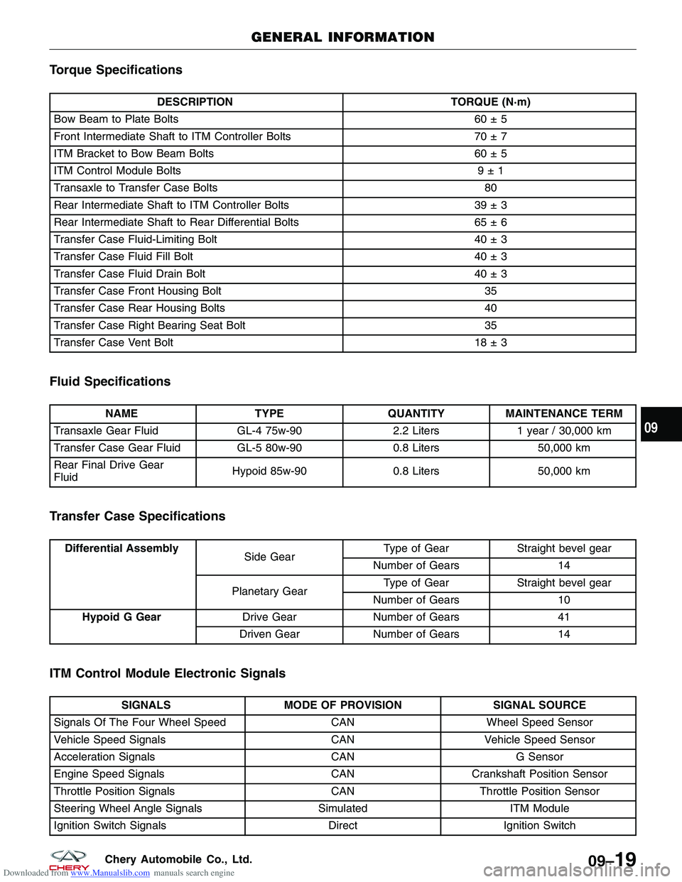
Downloaded from www.Manualslib.com manuals search engine Torque Specifications
DESCRIPTIONTORQUE (N·m)
Bow Beam to Plate Bolts 60 ± 5
Front Intermediate Shaft to ITM Controller Bolts 70 ± 7
ITM Bracket to Bow Beam Bolts 60 ± 5
ITM Control Module Bolts 9 ± 1
Transaxle to Transfer Case Bolts 80
Rear Intermediate Shaft to ITM Controller Bolts 39 ± 3
Rear Intermediate Shaft to Rear Differential Bolts 65 ± 6
Transfer Case Fluid-Limiting Bolt 40 ± 3
Transfer Case Fluid Fill Bolt 40 ± 3
Transfer Case Fluid Drain Bolt 40 ± 3
Transfer Case Front Housing Bolt 35
Transfer Case Rear Housing Bolts 40
Transfer Case Right Bearing Seat Bolt 35
Transfer Case Vent Bolt 18 ± 3
Fluid Specifications
NAMETYPEQUANTITYMAINTENANCE TERM
Transaxle Gear Fluid GL-4 75w-902.2 Liters1 year / 30,000 km
Transfer Case Gear Fluid GL-5 80w-900.8 Liters50,000 km
Rear Final Drive Gear
Fluid Hypoid 85w-90
0.8 Liters50,000 km
Transfer Case Specifications
Differential Assembly
Side GearType of Gear Straight bevel gear
Number of Gears 14
Planetary Gear Type of Gear
Straight bevel gear
Number of Gears 10
Hypoid G Gear Drive GearNumber of Gears 41
Driven Gear Number of Gears 14
ITM Control Module Electronic Signals
SIGNALSMODE OF PROVISION SIGNAL SOURCE
Signals Of The Four Wheel Speed CANWheel Speed Sensor
Vehicle Speed Signals CANVehicle Speed Sensor
Acceleration Signals CANG Sensor
Engine Speed Signals CANCrankshaft Position Sensor
Throttle Position Signals CANThrottle Position Sensor
Steering Wheel Angle Signals SimulatedITM Module
Ignition Switch Signals DirectIgnition Switch
GENERAL INFORMATION
09
09–19Chery Automobile Co., Ltd.
Page 1305 of 1903
Downloaded from www.Manualslib.com manuals search engine WARNING!
Do not remove the strut rod nut while the strut assembly is installed in the vehicle, or before the coil spring is
compressed with a spring compressor. The spring is held under high pressure and must be compressed before
the strut rod nut can be removed.
CAUTION:
At no time when servicing a vehicle can a sheet metal screw, bolt, or other metal fastener be
installed in the shock tower to replace the original plastic clamp. It may come in contact with the
strut or coil spring.
CAUTION:
The wheel bearing will be damaged if the vehicle is rolled with the axle shaft hub nut loose.
Operation
The front suspension utilizes a MacPherson strut system. This suspension system incorporates a strut assembly that
takes the place of the upper arm and ball joint. The strut performs the function of a shock absorber and is encom-
passed by a coil spring.
Specifications
Torque Specifications
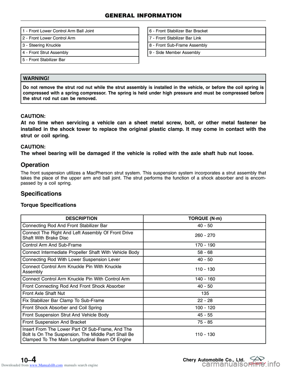
DESCRIPTIONTORQUE (N·m)
Connecting Rod And Front Stabilizer Bar 40 - 50
Connect The Right And Left Assembly Of Front Drive
Shaft With Brake Disc 260 - 270
Control Arm And Sub-Frame 170 - 190
Connect Intermediate Propeller Shaft With Vehicle Body 58 - 68
Connecting Rod With Lower Suspension Lever 40 - 50
Connect Control Arm Knuckle Pin With Knuckle
Assembly 110 - 130
Connect Control Arm Knuckle Pin With Control Arm 140 - 160
Front Connecting Rod And Front Shock Absorber 40 - 50
Front Axle Shaft Nut 135
Fix Stabilizer Bar Clamp To Sub-Frame 22 - 28
Front Shock Absorber and Coil Spring 100 - 120
Front Suspension Strut And Vehicle Body 45 - 55
Front Suspension And Bracket 75 - 85
Insert From The Lower Part Of Sub-Frame, And The
Bolt Is On The Suspension. The Middle Part Shall Be
Clamped To The Main Longitudinal Beam Of Engine 110 - 130
1 - Front Lower Control Arm Ball Joint
2 - Front Lower Control Arm
3 - Steering Knuckle
4 - Front Strut Assembly
5 - Front Stabilizer Bar6 - Front Stabilizer Bar Bracket
7 - Front Stabilizer Bar Link
8 - Front Sub-Frame Assembly
9 - Side Member Assembly
GENERAL INFORMATION
LTSM100008
10–4Chery Automobile Co., Ltd.
Page 1312 of 1903
Downloaded from www.Manualslib.com manuals search engine Inspection
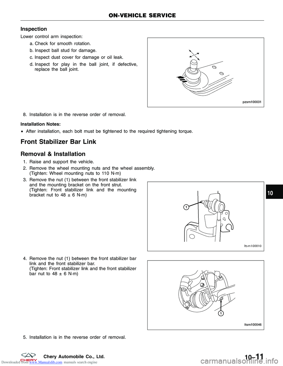
Lower control arm inspection:a. Check for smooth rotation.
b. Inspect ball stud for damage.
c. Inspect dust cover for damage or oil leak.
d. Inspect for play in the ball joint, if defective,
replace the ball joint.
8. Installation is in the reverse order of removal.
Installation Notes:
• After installation, each bolt must be tightened to the required tightening torque.
Front Stabilizer Bar Link
Removal & Installation
1. Raise and support the vehicle.
2. Remove the wheel mounting nuts and the wheel assembly.
(Tighten: Wheel mounting nuts to 110 N·m)
3. Remove the nut (1) between the front stabilizer link and the mounting bracket on the front strut.
(Tighten: Front stabilizer link and the mounting
bracket nut to 48 ± 6 N·m)
4. Remove the nut (1) between the front stabilizer bar link and the front stabilizer bar.
(Tighten: Front stabilizer link and the front stabilizer
bar nut to 48 ± 6 N·m)
5. Installation is in the reverse order of removal.
ON-VEHICLE SERVICE
PZSM100031
LTSM100010
LTSM100046
10
10–11Chery Automobile Co., Ltd.
Page 1313 of 1903
Downloaded from www.Manualslib.com manuals search engine Installation Notes:
•After installation, each bolt must be tightened to the required tightening torque.
Front Stabilizer Bar
Removal & Installation
1. Raise and support the vehicle.
2. Remove the wheel mounting nuts and the wheel assembly.
(Tighten: Wheel mounting nuts to 110 N·m)
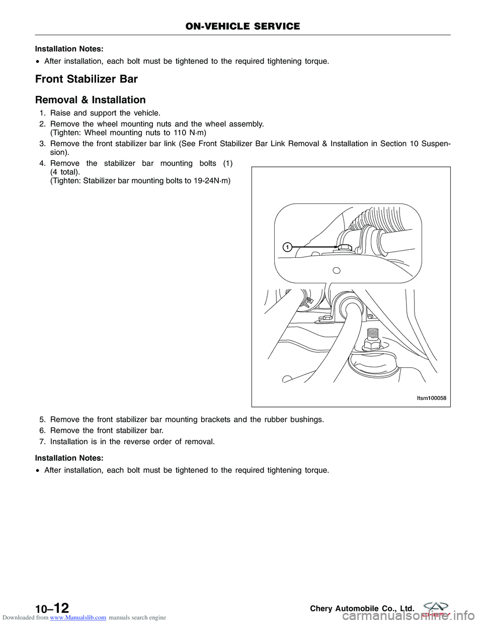
3. Remove the front stabilizer bar link (See Front Stabilizer Bar Link Removal & Installation in Section 10 Suspen- sion).
4. Remove the stabilizer bar mounting bolts (1) (4 total).
(Tighten: Stabilizer bar mounting bolts to 19-24N·m)
19 - 24 N·m)
5. Remove the front stabilizer bar mounting brackets and the rubber bushings.
6. Remove the front stabilizer bar.
7. Installation is in the reverse order of removal.
Installation Notes:
• After installation, each bolt must be tightened to the required tightening torque.
ON-VEHICLE SERVICE
LTSM100058
10–12Chery Automobile Co., Ltd.
Page 1316 of 1903
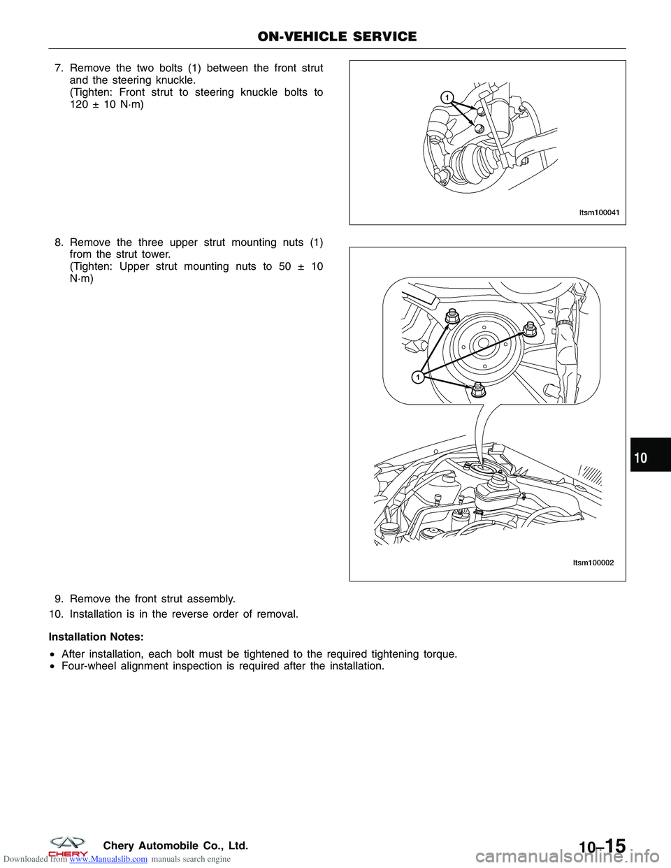
Downloaded from www.Manualslib.com manuals search engine 7. Remove the two bolts (1) between the front strutand the steering knuckle.
(Tighten: Front strut to steering knuckle bolts to
120 ± 10 N·m)
8. Remove the three upper strut mounting nuts (1) from the strut tower.
(Tighten: Upper strut mounting nuts to 50 ± 10
N·m)
9. Remove the front strut assembly.
10. Installation is in the reverse order of removal.
Installation Notes:
• After installation, each bolt must be tightened to the required tightening torque.
• Four-wheel alignment inspection is required after the installation.
ON-VEHICLE SERVICE
LTSM100041
LTSM100002
10
10–15Chery Automobile Co., Ltd.
Page 1341 of 1903
Downloaded from www.Manualslib.com manuals search engine 3. Check the tires on the vehicle. The tires are to beinflated to the recommended air pressure. All tires
must be the same size and in good condition with
approximately the same tread wear.
4. Check the front tire and wheel assemblies for excessive radial runout.
5. Inspect all suspension component fasteners for looseness and proper torque.
6. Inspect all ball joints and all steering linkage for looseness and any sign of wear or damage.
7. Inspect the rubber bushings on all the suspension components for signs of wear or deterioration. If any bushings show signs of wear or deterioration, they should be replaced prior to aligning the vehicle.
8. Check vehicle curb height.
Wheel Alignment Setup
1. Position the vehicle on an alignment rack.
2. Install all required alignment equipment on the vehicle, per the alignment equipment manufacturer’s instructions. On this vehicle, a four-wheel alignment is recommended.
3. Read the vehicle’s current front and rear alignment settings. Compare the vehicle’s current alignment settings to the vehicle specifications for camber, caster and toe-in.
NOTE :
Prior to reading the vehicle’s alignment readouts, the front and rear of vehicle should be jounced. Induce jounce (rear
first, then front) by grasping the center of the bumper and jouncing each end of the vehicle an equal number of
times. The bumper should always be released when vehicle is at the bottom of the jounce cycle.
Specifications
Torque Specifications
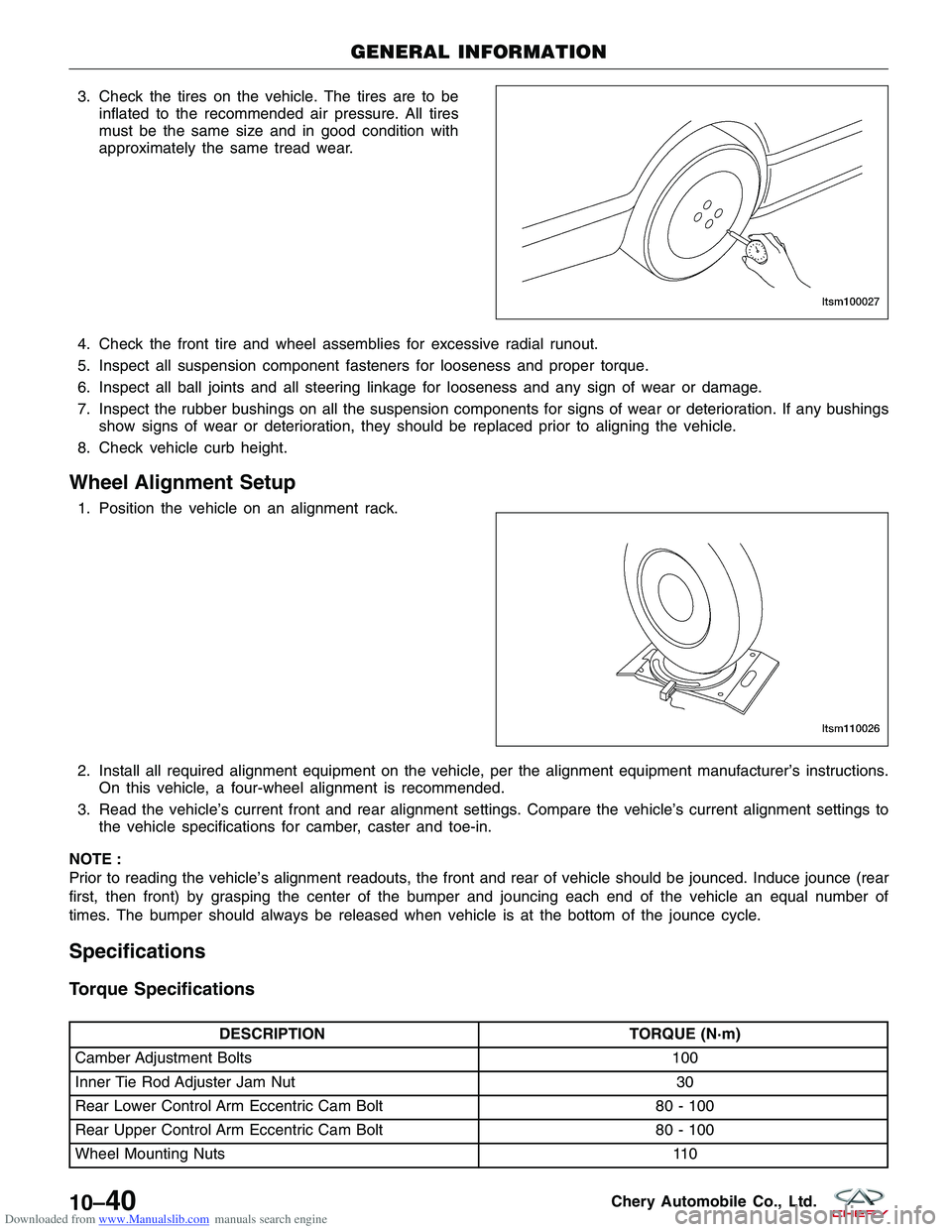
DESCRIPTION TORQUE (N·m)
Camber Adjustment Bolts 100
Inner Tie Rod Adjuster Jam Nut 30
Rear Lower Control Arm Eccentric Cam Bolt 80 - 100
Rear Upper Control Arm Eccentric Cam Bolt 80 - 100
Wheel Mounting Nuts 110
GENERAL INFORMATION
LTSM100027
LTSM110026
10–40Chery Automobile Co., Ltd.
Page 1346 of 1903
Downloaded from www.Manualslib.com manuals search engine Rear Wheel Alignment
Rear Wheel Alignment Specifications
NOTE :
If the vehicle has been in an accident causing the rear axle components to be damaged, the damaged components
must be replaced before performing a rear wheel alignment.
REAR WHEEL ALIGNMENT
REAR WHEEL ALIGNMENT PREFERRED SETTINGACCEPTABLE RANGE
Camber -54’-24’ to -1°24’
Toe-Individual -5’+5’ to -15’
Rear Axle Toe-In Adjustment
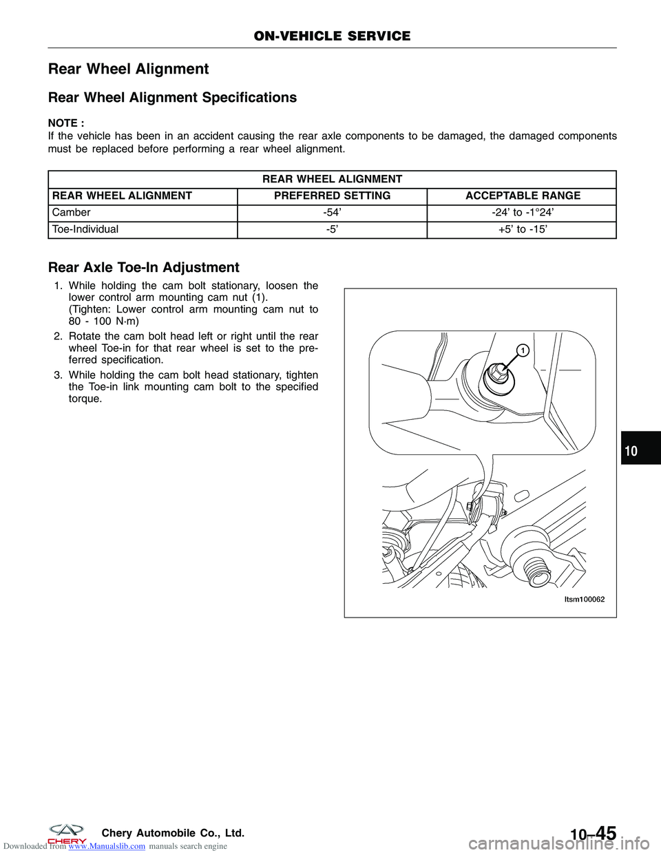
1. While holding the cam bolt stationary, loosen the
lower control arm mounting cam nut (1).
(Tighten: Lower control arm mounting cam nut to
80 - 100 N·m)
2. Rotate the cam bolt head left or right until the rear wheel Toe-in for that rear wheel is set to the pre-
ferred specification.
3. While holding the cam bolt head stationary, tighten the Toe-in link mounting cam bolt to the specified
torque.
ON-VEHICLE SERVICE
BESM100031
10
10–45Chery Automobile Co., Ltd.
Page 1347 of 1903
Downloaded from www.Manualslib.com manuals search engine Rear Camber Adjustment
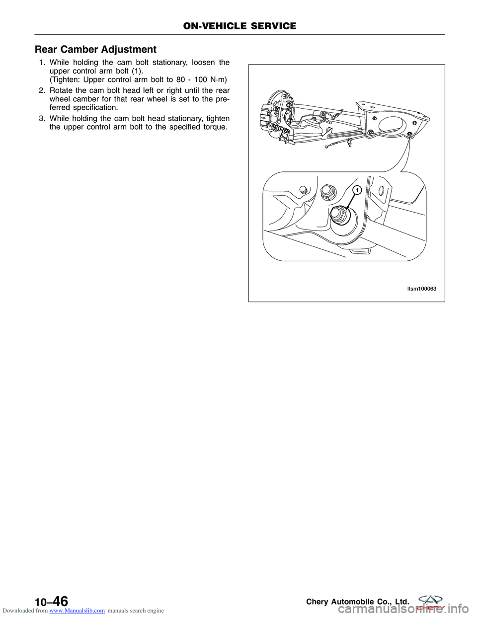
1. While holding the cam bolt stationary, loosen theupper control arm bolt (1).
(Tighten: Upper control arm bolt to 80 - 100 N·m)
2. Rotate the cam bolt head left or right until the rear wheel camber for that rear wheel is set to the pre-
ferred specification.
3. While holding the cam bolt head stationary, tighten the upper control arm bolt to the specified torque.
ON-VEHICLE SERVICE
BESM100031
10–46Chery Automobile Co., Ltd.