Page 1473 of 1903
Downloaded from www.Manualslib.com manuals search engine 5. Remove the wheel speed sensor mounting bolt (1).(Tighten: Wheel speed sensor mounting bolt to
10 N·m)
6. Remove the front wheel speed sensor.
Rear Wheel Speed Sensor
Removal & Installation
1. Disconnect the negative battery cable.
2. Raise and support the vehicle.
3. Remove the wheel mounting nuts and the tire and wheel assembly. (Tighten: Wheel mounting nuts to 110 N·m)
4. Disconnect the rear wheel speed sensor electrical connector (1).
5. Remove the rear hub and bearing assembly (See Rear Hub and Bearing Removal & Installation in Section 09 Driveline & Axle).
6. Remove the rear wheel speed sensor with the rear hub and bearing. NOTE: The rear wheel speed sensor is integrated into the rear hub and bearing assembly and a one piece
sealed unit.
ON-VEHICLE SERVICE
LTSM120026
LTSM120027
LTSM120028
12–78Chery Automobile Co., Ltd.
Page 1475 of 1903
Downloaded from www.Manualslib.com manuals search engine GENERAL INFORMATION
Description
The parking brakes consist of the following components:
•Hand-operated parking brake lever
• Parking brake cables (one each side)
• Parking brake controls
Operation
All vehicles are equipped with a center-mounted, hand-operated parking brake lever mounted between the front
seats. A tensioner is built into the equalizer mounted on the end of the lever’s output cable. There is an individual
parking brake cable for each rear wheel that joins a parking brake cable equalizer, attached to the parking brake
lever, to the rear parking brakes. The parking brake cables are made of flexible steel cable.
Specifications
Torque Specifications
DESCRIPTION TORQUE (N·m)
Parking Brake Cable Routing Clamp Bolt 12
Parking Brake Cable Bracket Bolts 12
Parking Brake Lever Nuts 30
Wheel Mounting Nuts 110
Special Tools
Brake Measuring Gauge
J21177-A
12–80Chery Automobile Co., Ltd.
Page 1477 of 1903

Downloaded from www.Manualslib.com manuals search engine DIAGNOSIS & TESTING
Parking Brake Warning Light
The parking brake switch is incorporated in the circuit for the red warning lamp in the dash. The switch will cause the
lamp to illuminate only when the parking brakes are applied. If the lamp remains on after parking brake release, the
switch or circuit is faulty.
Parking Brake Operation
The leading cause of improper parking brake operation, is excessive clearance between the parking brake shoes and
the shoe braking surface. Excessive clearance is a result of lining and/or drum wear, drum surface machined over-
size.
In most cases, the actual cause of an improperly functioning parking brake (too loose/too tight/won’t hold), can be
traced to a parking brake component.
Inspect the following when diagnosing a parking brake problem:
•Brake shoe wear
• Drum surface (in rear rotor) machined oversize
• Front cable not secured to lever
• Rear cable not attached to actuator
• Rear cable seized
• Parking brake lever not seated
• Parking brake lever bind
Parking Brake Adjustment
Adjust the parking brake only if the parking brake lever can be pulled up more than 3 notches without having an
adequate solid braking effect.
NOTE :
Excessive parking brake lever travel (sometimes described as a loose lever or too loose condition), could be the
result of worn brake shoes, improper brake shoe adjustment, or improperly assembled brake parts. A too loose con-
dition can also be caused by inoperative or improperly assembled parking brake components. Always confirm that the
parking brake components are assembled properly. Perform the following procedure to adjust the parking brake:
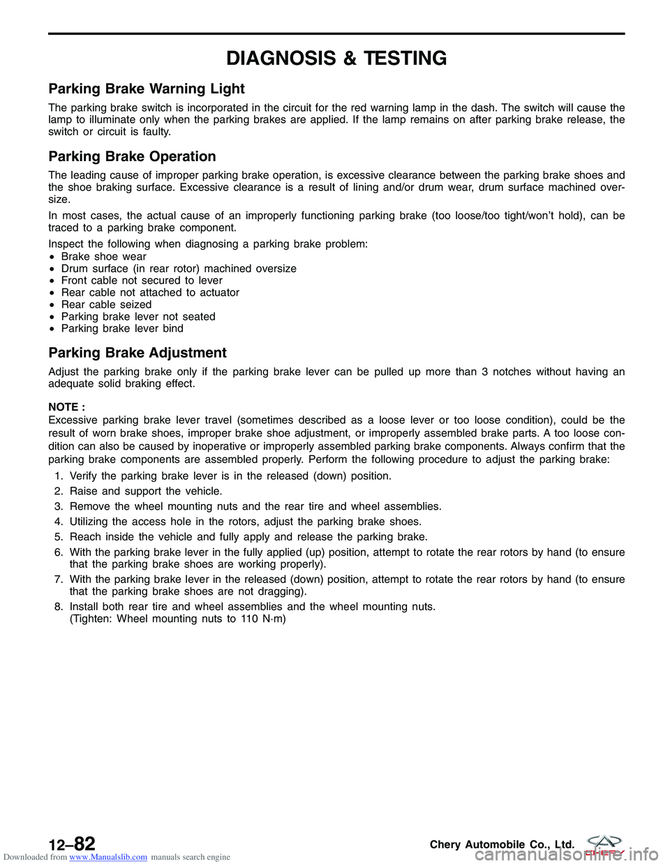
1. Verify the parking brake lever is in the released (down) position.
2. Raise and support the vehicle.
3. Remove the wheel mounting nuts and the rear tire and wheel assemblies.
4. Utilizing the access hole in the rotors, adjust the parking brake shoes.
5. Reach inside the vehicle and fully apply and release the parking brake.
6. With the parking brake lever in the fully applied (up) position, attempt to rotate the rear rotors by hand (to ensure that the parking brake shoes are working properly).
7. With the parking brake lever in the released (down) position, attempt to rotate the rear rotors by hand (to ensure that the parking brake shoes are not dragging).
8. Install both rear tire and wheel assemblies and the wheel mounting nuts. (Tighten: Wheel mounting nuts to 110 N·m)
12–82Chery Automobile Co., Ltd.
Page 1479 of 1903
Downloaded from www.Manualslib.com manuals search engine ON-VEHICLE SERVICE
Parking Brake Lever
Removal & Installation
1. Block the tire and wheel assemblies so the vehicle does not move once the vehicle parking brake lever isreleased.
2. Remove the center console (See Center Console Removal & Installation in Section 15 Body & Accessories).
3. Loosen the adjusting nut (2) on the lever’s output cable, taking tension off parking brake cables.
4. Back the nut off until it is flush with the end of the output cable.
5. Remove the bolts (1) attaching the parking brake lever to the vehicle.
(Tighten: Parking brake lever bolts to 30 N·m)
6. Remove the parking brake assembly.
7. Installation is in the reverse order of removal.
Installation Notes:
• After installation, adjust the parking brake cable as necessary (See Parking Brake Adjustment in Section 12
Brakes).
LTSM120031
12–84Chery Automobile Co., Ltd.
Page 1480 of 1903
Downloaded from www.Manualslib.com manuals search engine Parking Brake Cable
Removal & Installation
1. Remove the parking brake lever (2).
2. Remove the adjusting bolt (1) from the parking brake lever.
3. Loosen the right and left parking brake cable bracket bolts (3).
4. Remove the parking brake cable (4).
5. Remove the right and left parking brake cable bolts.
6. Remove the parking brake cable (1) from the brakeactuator.
7. Installation is in the reverse order of removal.
NOTE :
The parking brake should be adjusted after replacing
brake shoes or hand brake cable.
• Loosen the parking brake handle.
• Apply the brake pedal once.
• Pull the parking brake handle up four clicks.
• After completing the above procedure, loosen the
parking brake and inspect the rear wheels to check if
they can be turned freely. If the wheels are still tight,
repeat the adjustment procedure.
ON-VEHICLE SERVICE
LTSM120029
LTSM120030
12
12–85Chery Automobile Co., Ltd.
Page 1481 of 1903
Downloaded from www.Manualslib.com manuals search engine Parking Brake Shoes
Removal & Installation
1. Raise and support the vehicle.
2. Remove the rear wheel mounting nuts and both rear tire and wheel assemblies.(Tighten: Wheel mounting nuts to 110 N·m)
3. Access and remove rear brake rotor (See Rear Brake Rotor Removal & Installation in Section 12
Brakes).
4. Turn the brake shoe adjuster wheel until the adjuster is at shortest length.
5. Remove the brake shoe hold-down springs (3) and pins (6). Rotate the pins 90° to disengage.
6. Remove the parking brake cable from the arm on the rear parking brake shoe.
7. Remove the brake shoes (2, 7), adjuster (4) and lower return spring (5) as an assembly from the
support plate.
8. Remove the lower return spring (5) and adjuster (4) from the shoes (2, 7).
9. Remove the parking brake shoes.
10. Installation is in the reverse order of removal.
ON-VEHICLE SERVICE
LTSM120037
BESM120021
12–86Chery Automobile Co., Ltd.
Page 1482 of 1903
Downloaded from www.Manualslib.com manuals search engine Installation Notes:
•Perform the following to measure and adjust parking brake shoes:
1. Using a brake measuring gauge or equivalent, measure the inside diameter of parking brake drum (1).
2. Place the brake measuring gauge over the
parking brake shoes at their widest point.
3. Using the adjuster wheel, adjust the parking brake shoes until the linings on both parking brake shoes just
touch the jaws on the brake measuring gauge.
• After installation, adjust the parking brake cable as
necessary (See Parking Brake Adjustment in Sec-
tion 12 Brakes).
BRAKE SHOES NEW THICKNESSMINIMUM THICKNESS
Rear Shoes 2.5 mm1.5 mm
ON-VEHICLE SERVICE
BESM120024
LTSM120039
12
12–87Chery Automobile Co., Ltd.
Page 1508 of 1903

Downloaded from www.Manualslib.com manuals search engine GENERAL INFORMATION
Description
All models are equipped with a common HVAC housing assembly that combines A/C and heating capabilities into a
single unit mounted within the passenger compartment. The HVAC housing assembly consists of three separate
housings:
•HVAC housing — The HVAC housing is mounted to the dash panel behind the instrument panel and contains
the A/C evaporator. The HVAC housing has mounting provisions for the air inlet housing, blower motor and the
air distribution housing.
• Air distribution housing — The air distribution housing is mounted to the rear of the HVAC housing and con-
tains the heater core, blend-air and mode-air doors and door linkage.
• Air inlet housing — The air inlet housing is mounted to the passenger side end of the HVAC housing. The air
inlet housing contains the recirculation-air door and actuator.
Operation
The A/C system is designed for the use of a non-CFC, R-134a refrigerant and uses an A/C evaporator to cool and
dehumidify the incoming air prior to blending it with the heated air. Temperature control determines the discharge air
temperature by operating the temperature control cable, which moves the blend-air door. This allows an almost
immediate control of the output air temperature of the system. The mode door cable operates the mode-air doors
which direct the flow of the conditioned air out the various air outlets, depending on the mode selected. When
equipped with A/C, the recirculation door actuator operates the recirculation-air door which closes off the fresh air
intake and recirculates the air already inside the vehicle. The electric recirculation door actuator and the blower motor
are connected to the vehicle electrical system by the instrument panel wire harness. The blower motor controls the
velocity of air flowing through the HVAC housing assembly by spinning the blower wheel within the HVAC housing at
the selected speed by use of the blower motor resistor, which is around the blower motor.
The air distribution housing must be removed from the HVAC housing and disassembled for service of the blend-air
and mode-air doors. The air inlet housing must be removed from the HVAC housing and disassembled for service of
the recirculation-air door. The HVAC housing must be removed from the vehicle and disassembled for service of the
A/C evaporator.
Specifications
Torque Specifications
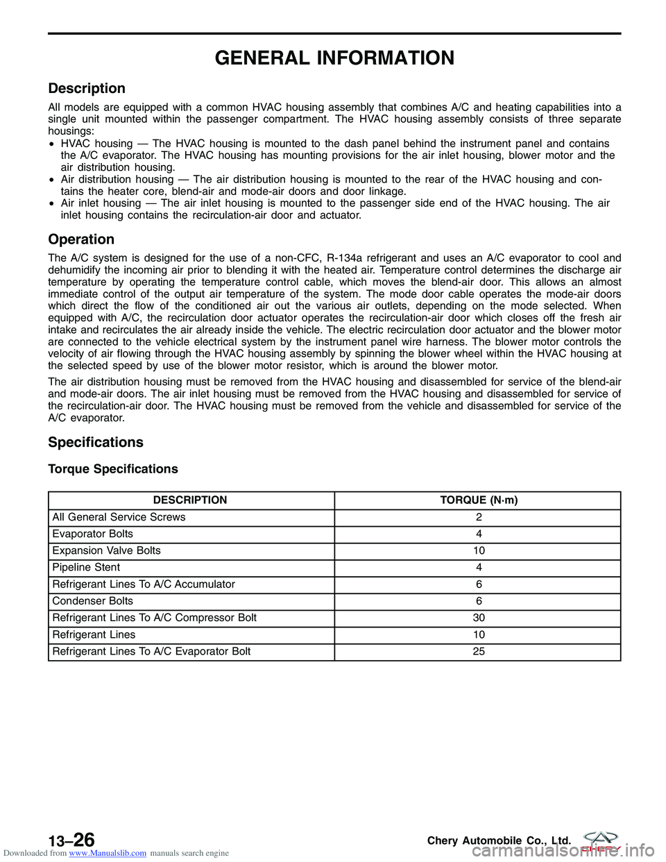
DESCRIPTION TORQUE (N·m)
All General Service Screws 2
Evaporator Bolts 4
Expansion Valve Bolts 10
Pipeline Stent 4
Refrigerant Lines To A/C Accumulator 6
Condenser Bolts 6
Refrigerant Lines To A/C Compressor Bolt 30
Refrigerant Lines 10
Refrigerant Lines To A/C Evaporator Bolt 25
13–26Chery Automobile Co., Ltd.