Page 57 of 92

PERIODIC MAINTENANCE AND MINOR REPAIR
6-15
2
3
4
5
67
8
9
EAU34301
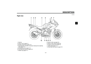
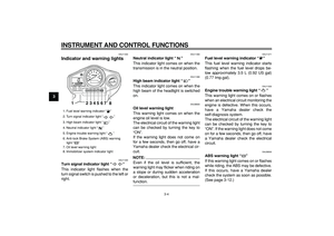
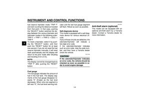
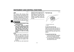
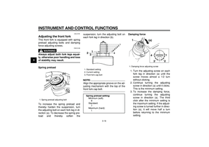
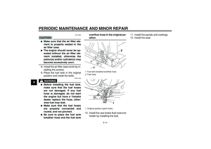
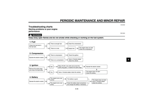
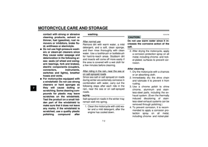
Adjusting the engine idling
speed
The engine idling speed must be
checked and, if necessary, adjusted as
follows at the intervals specified in the
periodic maintenance and lubrication
chart.
The engine should be warm before
making this adjustment.
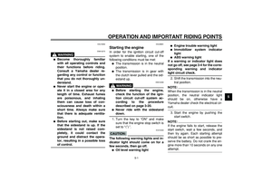
Check the engine idling speed and, if
necessary, adjust it to specification by
turning the idle adjusting screw. To in-
crease the engine idling speed, turn the
screw in direction (a). To decrease the
engine idling speed, turn the screw in
direction (b).
NOTE:
If the specified idling speed cannot be
obtained as described above, have a
Yamaha dealer make the adjustment.
EAU21382
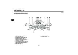
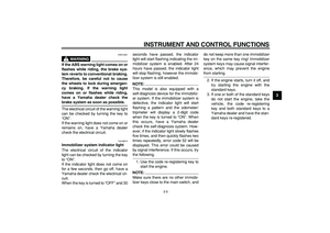
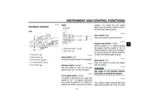
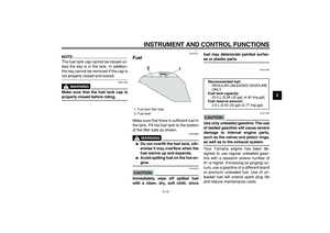
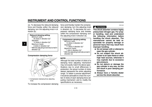
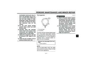
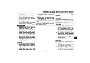
Checking the throttle cable
free play
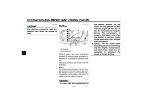
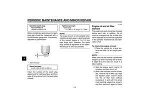
The throttle cable free play should mea-
sure 3.0–5.0 mm (0.12–0.20 in) at the
throttle grip. Periodically check the
throttle cable free play and, if neces-
sary, have a Yamaha dealer adjust it.
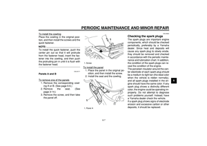
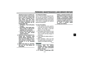
1. Idle adjusting screw
Engine idling speed:
1100–1200 r/min1(a)
(b)
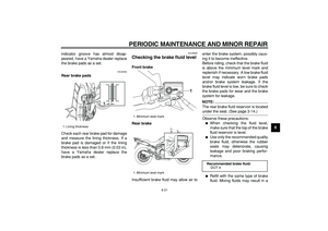
1. Throttle cable free play
1
Page 58 of 92

PERIODIC MAINTENANCE AND MINOR REPAIR
6-16
1
2
3
4
5
6
7
8
9
EAU21401
Valve clearance
The valve clearance changes with use,
resulting in improper air-fuel mixture
and/or engine noise. To prevent this
from occurring, the valve clearance
must be adjusted by a Yamaha dealer
at the intervals specified in the periodic
maintenance and lubrication chart.
EAU33041
Tires
To maximize the performance, durabil-
ity, and safe operation of your motorcy-
cle, note the following points regarding
the specified tires.
Tire air pressure
The tire air pressure should be checked
and, if necessary, adjusted before each
ride.
WARNING
EWA10500
�
The tire air pressure must be
checked and adjusted on cold
tires (i.e., when the temperature
of the tires equals the ambient
temperature).
�
The tire air pressure must be ad-
justed in accordance with the
riding speed and with the total
weight of rider, passenger, car-
go, and accessories approved
for this model.
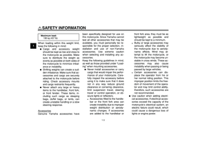
WARNING
EWA11020
Because loading has an enormous
impact on the handling, braking,
performance and safety characteris-
tics of your motorcycle, you should
keep the following precautions in
mind.
�
NEVER OVERLOAD THE MO-
TORCYCLE! Operation of an
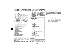
Tire air pressure (measured on cold
tires):
0–90 kg (0–198 lb):
Front:
225 kPa (33 psi) (2.25 kgf/cm
2
)
Rear:
250 kPa (36 psi) (2.50 kgf/cm
2
)
90–198 kg (198–437 lb):
Front:
225 kPa (33 psi) (2.25 kgf/cm
2
)
Rear:
290 kPa (42 psi) (2.90 kgf/cm
2
)
High-speed riding:
Front:
225 kPa (33 psi) (2.25 kgf/cm
2
)
Rear:
250 kPa (36 psi) (2.50 kgf/cm
2
)
Maximum load*:
198 kg (437 lb)
* Total weight of rider, passenger, car-
go and accessories
Page 59 of 92

PERIODIC MAINTENANCE AND MINOR REPAIR
6-17
2
3
4
5
67
8
9 overloaded motorcycle may re-
sult in tire damage, loss of con-
trol, or severe injury. Make sure
that the total weight of rider,
passenger, cargo, and accesso-
ries does not exceed the speci-
fied maximum load for the
vehicle.
�
Do not carry along loosely
packed items, which can shift
during a ride.
�
Securely pack the heaviest
items close to the center of the
motorcycle and distribute the
weight evenly on both sides.
�
Adjust the suspension and tire
air pressure with regard to the
load.
�
Check the tire condition and air
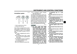
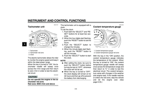
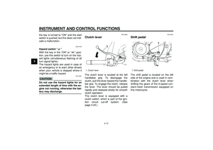
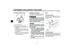
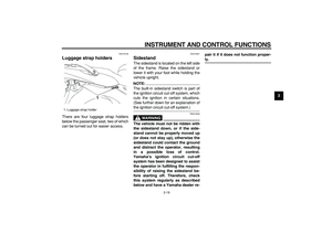
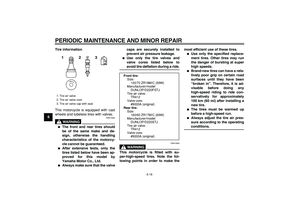
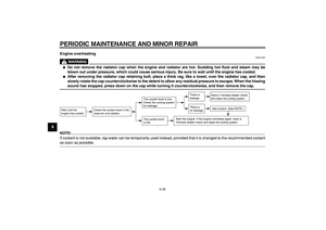
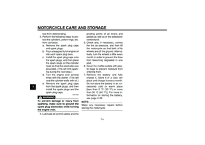
pressure before each ride.Tire inspection
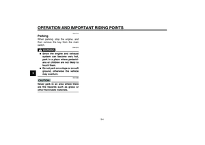
The tires must be checked before each
ride. If the center tread depth reaches
the specified limit, if the tire has a nail or
glass fragments in it, or if the sidewall is
cracked, have a Yamaha dealer re-
place the tire immediately.
NOTE:
The tire tread depth limits may differ
from country to country. Always comply
with the local regulations.
WARNING
EWA10470
�
Have a Yamaha dealer replace
excessively worn tires. Besides
being illegal, operating the vehi-
cle with excessively worn tires
decreases riding stability and
can lead to loss of control.
�
The replacement of all wheel
and brake related parts, includ-
ing the tires, should be left to a
Yamaha dealer, who has the
necessary professional knowl-
edge and experience.
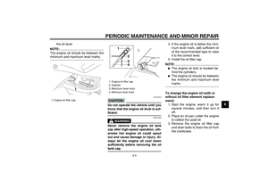
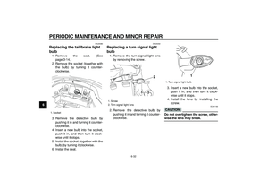
1. Tire tread depth
2. Tire sidewall
Minimum tire tread depth (front and
rear):
1.6 mm (0.06 in)
21
Page 60 of 92

PERIODIC MAINTENANCE AND MINOR REPAIR
6-18
1
2
3
4
5
6
7
8
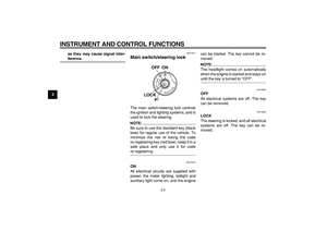
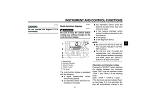
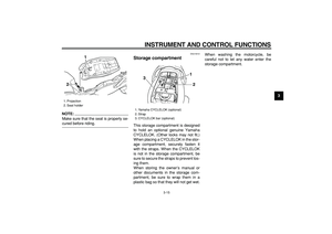
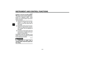
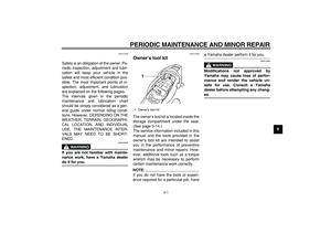
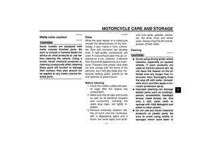
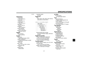
9Tire information
This motorcycle is equipped with cast
wheels and tubeless tires with valves.
WARNING
EWA10900
�
The front and rear tires should
be of the same make and de-
sign, otherwise the handling
characteristics of the motorcy-
cle cannot be guaranteed.
�
After extensive tests, only the
tires listed below have been ap-
proved for this model by
Yamaha Motor Co., Ltd.
�
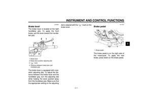
Always make sure that the valvecaps are securely installed to
prevent air pressure leakage.
�
Use only the tire valves and
valve cores listed below to
avoid tire deflation during a ride.
WARNING
EWA10600
This motorcycle is fitted with su-
per-high-speed tires. Note the fol-
lowing points in order to make themost efficient use of these tires.
�
Use only the specified replace-
ment tires. Other tires may run
the danger of bursting at super
high speeds.
�
Brand-new tires can have a rela-
tively poor grip on certain road
surfaces until they have been
“broken in”. Therefore, it is ad-
visable before doing any
high-speed riding to ride con-
servatively for approximately
100 km (60 mi) after installing a
new tire.
�
The tires must be warmed up
before a high-speed run.
�
Always adjust the tire air pres-
sure according to the operating
conditions.
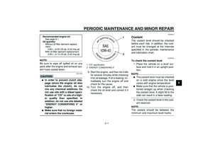
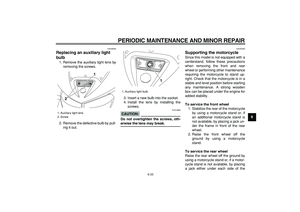
1. Tire air valve
2. Tire air valve core
3. Tire air valve cap with seal
123
Front tire:
Size:
120/70 ZR18M/C (59W)
Manufacturer/model:
DUNLOP/D220FSTJ
Tire air valve:
TR412
Valve core:
#9000A (original)
Rear tire:
Size:
160/60 ZR17M/C (69W)
Manufacturer/model:
DUNLOP/D220STJ
Tire air valve:
TR412
Valve core:
#9000A (original)
Page 61 of 92

PERIODIC MAINTENANCE AND MINOR REPAIR
6-19
2
3
4
5
67
8
9
EAU21960
Cast wheels
To maximize the performance, durabil-
ity, and safe operation of your vehicle,
note the following points regarding the
specified wheels.
�
The wheel rims should be checked
for cracks, bends or warpage be-
fore each ride. If any damage is
found, have a Yamaha dealer re-
place the wheel. Do not attempt
even the smallest repair to the
wheel. A deformed or cracked
wheel must be replaced.
�
The wheel should be balanced
whenever either the tire or wheel
has been changed or replaced. An
unbalanced wheel can result in
poor performance, adverse han-
dling characteristics, and a short-
ened tire life.
�
Ride at moderate speeds after
changing a tire since the tire sur-
face must first be “broken in” for it
to develop its optimal characteris-
tics.
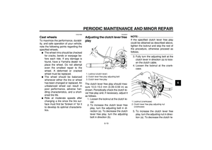
EAU22041
Adjusting the clutch lever free
play
The clutch lever free play should mea-
sure 10.0–15.0 mm (0.39–0.59 in) as
shown. Periodically check the clutch le-
ver free play and, if necessary, adjust it
as follows.
1. Loosen the locknut at the clutch le-
ver.
2. To increase the clutch lever free
play, turn the adjusting bolt in di-
rection (a). To decrease the clutch
lever free play, turn the adjusting
bolt in direction (b).
NOTE:
If the specified clutch lever free play
could be obtained as described above,
tighten the locknut and skip the rest of
the procedure, otherwise proceed as
follows.
3. Fully turn the adjusting bolt at the
clutch lever in direction (a) to loos-
en the clutch cable.
4. Loosen the locknut at the crank-
case.
5. To increase the clutch lever free
play, turn the adjusting nut in direc-
tion (a). To decrease the clutch le-
1. Locknut (clutch lever)
2. Clutch lever free play adjusting bolt
3. Clutch lever free play
12
3
(a)
(b)
1. Locknut (crankcase)
2. Clutch lever free play adjusting nut
(crankcase)
12
(a)(b)
Page 62 of 92
.
6. Tighten the locknut at the clutch le-
ver and the crankcase.
EAU22270
Ad")
PERIODIC MAINTENANCE AND MINOR REPAIR
6-20
1
2
3
4
5
6
7
8
9
ver free play, turn the adjusting nut
in direction (b).
6. Tighten the locknut at the clutch le-
ver and the crankcase.
EAU22270
Adjusting the rear brake light
switch
The rear brake light switch, which is ac-
tivated by the brake pedal, is properly
adjusted when the brake light comes
on just before braking takes effect. If
necessary, adjust the brake light switch
as follows.
Turn the adjusting nut while holding the
rear brake light switch in place. To
make the brake light come on earlier,
turn the adjusting nut in direction (a). To
make the brake light come on later, turn
the adjusting nut in direction (b).
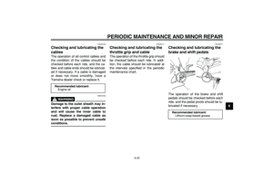
EAU22390
Checking the front and rear
brake pads
The front and rear brake pads must be
checked for wear at the intervals spec-
ified in the periodic maintenance and
lubrication chart.
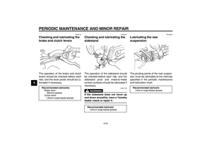
EAU22420
Front brake pads
Each front brake pad is provided with a
wear indicator groove, which allows
you to check the brake pad wear with-
out having to disassemble the brake.
To check the brake pad wear, check
the wear indicator groove. If a brake
pad has worn to the point that the wear
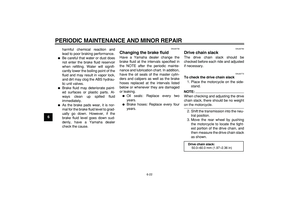
1. Rear brake light switch
2. Rear brake light switch adjusting nut
1
2 (a)(b)
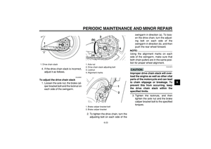
1. Brake pad wear indicator groove
1
Page 63 of 92

PERIODIC MAINTENANCE AND MINOR REPAIR
6-21
2
3
4
5
67
8
9
indicator groove has almost disap-
peared, have a Yamaha dealer replace
the brake pads as a set.
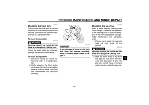
EAU22500
Rear brake pads
Check each rear brake pad for damage
and measure the lining thickness. If a
brake pad is damaged or if the lining
thickness is less than 0.8 mm (0.03 in),
have a Yamaha dealer replace the
brake pads as a set.
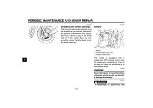
EAU36680
Checking the brake fluid level
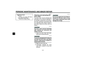
Front brake
Rear brake
Insufficient brake fluid may allow air toenter the brake system, possibly caus-
ing it to become ineffective.
Before riding, check that the brake fluid
is above the minimum level mark and
replenish if necessary. A low brake fluid
level may indicate worn brake pads
and/or brake system leakage. If the
brake fluid level is low, be sure to check
the brake pads for wear and the brake
system for leakage.
NOTE:
The rear brake fluid reservoir is located
under the seat. (See page 3-14.)
Observe these precautions:
�
When checking the fluid level,
make sure that the top of the brake
fluid reservoir is level.
�
Use only the recommended quality
brake fluid, otherwise the rubber
seals may deteriorate, causing
leakage and poor braking perfor-
mance.
�
Refill with the same type of brake
fluid. Mixing fluids may result in a
1. Lining thickness
1
1. Minimum level mark
1. Minimum level mark
1
1
Recommended brake fluid:
DOT 4
Page 64 of 92

PERIODIC MAINTENANCE AND MINOR REPAIR
6-22
1
2
3
4
5
6
7
8
9
harmful chemical reaction and
lead to poor braking performance.
�
Be careful that water or dust does
not enter the brake fluid reservoir
when refilling. Water will signifi-
cantly lower the boiling point of the
fluid and may result in vapor lock,
and dirt may clog the ABS hydrau-
lic unit valves.
�
Brake fluid may deteriorate paint-
ed surfaces or plastic parts. Al-
ways clean up spilled fluid
immediately.
�
As the brake pads wear, it is nor-
mal for the brake fluid level to grad-
ually go down. However, if the
brake fluid level goes down sud-
denly, have a Yamaha dealer
check the cause.
EAU22730
Changing the brake fluid
Have a Yamaha dealer change the
brake fluid at the intervals specified in
the NOTE after the periodic mainte-
nance and lubrication chart. In addition,
have the oil seals of the master cylin-
ders and calipers as well as the brake
hoses replaced at the intervals listed
below or whenever they are damaged
or leaking.
�
Oil seals: Replace every two
years.
�
Brake hoses: Replace every four
years.
EAU22760
Drive chain slack
The drive chain slack should be
checked before each ride and adjusted
if necessary.
EAU22773
To check the drive chain slack
1. Place the motorcycle on the side-
stand.
NOTE:
When checking and adjusting the drive
chain slack, there should be no weight
on the motorcycle.
2. Shift the transmission into the neu-
tral position.
3. Move the rear wheel by pushing
the motorcycle to locate the tight-
est portion of the drive chain, and
then measure the drive chain slack
as shown.
Drive chain slack:
50.0–60.0 mm (1.97–2.36 in)