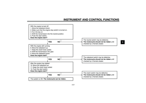
Page 49 of 92

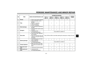
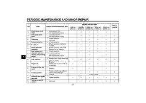
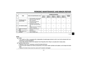
PERIODIC MAINTENANCE AND MINOR REPAIR
6-7
2
3
4
5
67
8
9
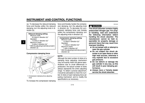
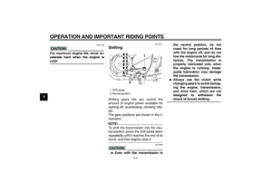
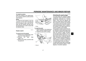
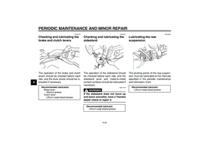
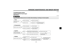
To install the cowling
Place the cowling in the original posi-
tion, and then install the screws and the
quick fastener.NOTE:
To install the quick fastener, push the
center pin out so that it will protrude
from the fastener head, insert the fas-
tener into the cowling, and then push
the protruding pin in until it is flush with
the fastener head.
EAU19171
Panels A and B
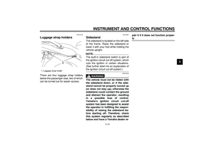
To remove one of the panels
1. Remove the corresponding cowl-
ing A or B. (See page 6-6.)
2. Remove the seat. (See
page 3-14.)
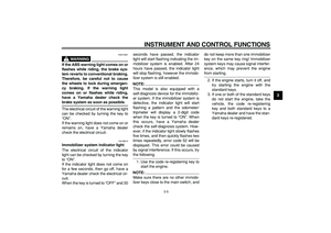
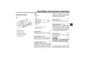
3. Remove the screw, and then take
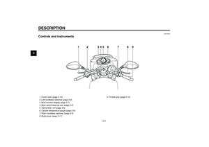
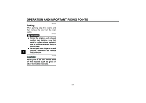
the panel off.To install the panel
1. Place the panel in the original po-
sition, and then install the screw.
2. Install the seat and the cowling.
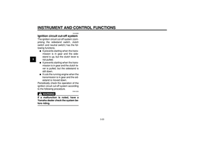
EAU19642
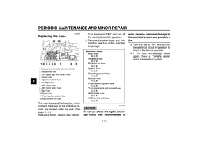
Checking the spark plugs
The spark plugs are important engine
components, which should be checked
periodically, preferably by a Yamaha
dealer. Since heat and deposits will
cause any spark plug to slowly erode,
they should be removed and checked
in accordance with the periodic mainte-
nance and lubrication chart. In addition,
the condition of the spark plugs can re-
veal the condition of the engine.
The porcelain insulator around the cen-
ter electrode of each spark plug should
be a medium-to-light tan (the ideal color
when the vehicle is ridden normally),
and all spark plugs installed in the en-
gine should have the same color. If any
spark plug shows a distinctly different
color, the engine could be operating im-
properly. Do not attempt to diagnose
such problems yourself. Instead, have
a Yamaha dealer check the vehicle.
If a spark plug shows signs of electrode
erosion and excessive carbon or other
deposits, it should be replaced.
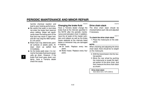
1. Screw
1. Panel A
1
1
Page 50 of 92

PERIODIC MAINTENANCE AND MINOR REPAIR
6-8
1
2
3
4
5
6
7
8
9
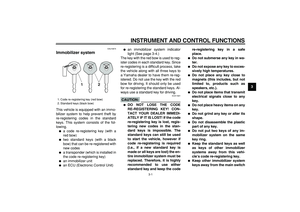
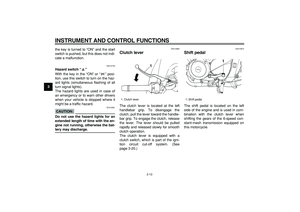
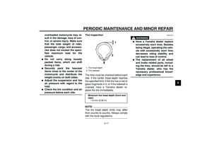
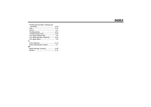
Before installing a spark plug, the spark
plug gap should be measured with a
wire thickness gauge and, if necessary,
adjusted to specification.
Clean the surface of the spark plug
gasket and its mating surface, and then
wipe off any grime from the spark plug
threads.
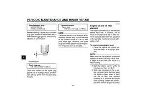
NOTE:
If a torque wrench is not available when
installing a spark plug, a good estimate
of the correct torque is 1/4–1/2 turn
past finger tight. However, the spark
plug should be tightened to the speci-
fied torque as soon as possible.
EAU19832
Engine oil and oil filter
element
The engine oil level should be checked
before each ride. In addition, the oil
must be changed and the oil filter ele-
ment replaced at the intervals specified
in the periodic maintenance and lubri-
cation chart.
To check the engine oil level
1. Place the vehicle on a level sur-
face and hold it in an upright posi-
tion.
NOTE:
Make sure that the vehicle is positioned
straight up when checking the oil level.
A slight tilt to the side can result in a
false reading.
2. Start the engine, warm it up for 15
minutes, and then turn it off.
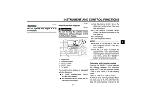
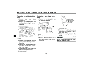
3. Wait a few minutes until the oil set-
tles, remove the oil filler cap, wipe
the dipstick clean, insert it back
into the oil filler hole (without
screwing it in and with the arrow
mark pointing upward as shown),
and then remove it again to check
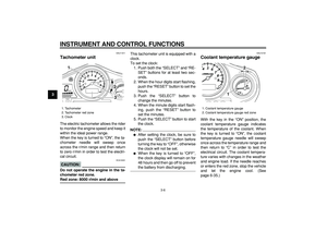
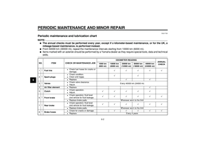
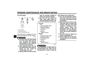
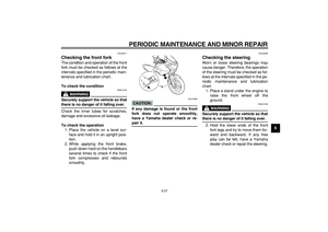
Specified spark plug:
NGK/DPR8EA-9
DENSO/X24EPR-U9
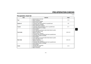
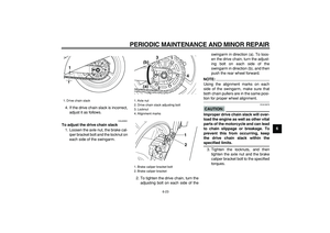
1. Spark plug gap
Spark plug gap:
0.8–0.9 mm (0.031–0.035 in)
1
Tightening torque:
Spark plug:
17.5 Nm (1.75 m·kgf, 12.7 ft·lbf)
Page 51 of 92

PERIODIC MAINTENANCE AND MINOR REPAIR
6-9
2
3
4
5
67
8
9
the oil level.
NOTE:
The engine oil should be between the
minimum and maximum level marks.
CAUTION:
ECA10010
Do not operate the vehicle until you
know that the engine oil level is suf-
ficient.
WARNING
EWA10360
Never remove the engine oil tank
cap after high-speed operation, oth-
erwise hot engine oil could spout
out and cause damage or injury. Al-
ways let the engine oil cool down
sufficiently before removing the oil
tank cap.
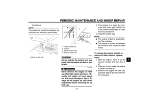
4. If the engine oil is below the mini-
mum level mark, add sufficient oil
of the recommended type to raise
it to the correct level.
5. Install the oil filler cap.
NOTE:
�
The engine oil tank is located be-
hind the cylinders.
�
The engine oil should be between
the minimum and maximum level
marks.
To change the engine oil (with or
without oil filter element replace-
ment)
1. Start the engine, warm it up for
several minutes, and then turn it
off.
2. Place an oil pan under the engine
to collect the used oil.
3. Remove the engine oil filler cap
and drain bolts to drain the oil from
the crankcase.
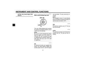
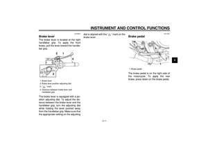
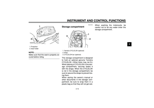
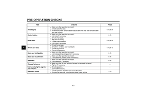
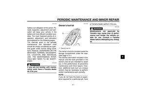
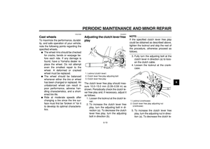
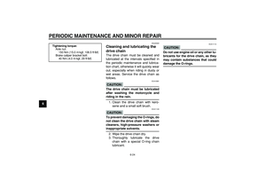
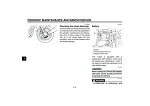
1. Engine oil filler cap
1
1. Engine oil filler cap
2. Dipstick
3. Maximum level mark
4. Minimum level mark
1
2
3
4
Page 52 of 92
PERIODIC MAINTENANCE AND MINOR REPAIR
6-10
1
2
3
4
5
6
7
8
9
NOTE:
Skip steps 4–6 if the oil filter element is
not being replaced.
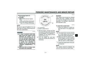
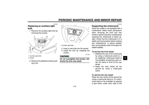
4. Remove the oil filter element cover
by removing the bolts.5. Remove and replace the oil filter
element and O-rings.
6. Install the oil filter element cover byinstalling the bolts, then tightening
them to the specified torque.
NOTE:
Make sure that the O-rings are properly
seated.
7. Install the engine oil drain bolts,
and then tighten them to the spec-
ified torques.
8. Add the specified amount of the
recommended engine oil, and then
install and tighten the oil filler cap.
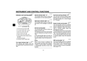
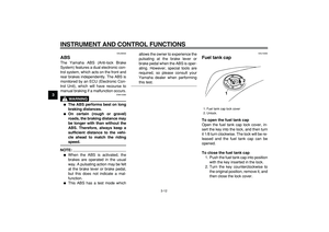
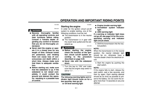
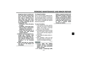
1. Engine oil drain bolt A
1
1. Engine oil drain bolt B
2. Oil filter element cover
3. Bolt
1. Oil filter element
2. O-ring12
2
3
1
2
Tightening torque:
Oil filter element cover bolt:
10 Nm (1.0 m·kgf, 7.2 ft·lbf)
Tightening torques:
Engine oil drain bolt A:
35 Nm (3.5 m·kgf, 25 ft·lbf)
Engine oil drain bolt B:
30 Nm (3.0 m·kgf, 21.7 ft·lbf)
Page 53 of 92

PERIODIC MAINTENANCE AND MINOR REPAIR
6-11
2
3
4
5
67
8
9
NOTE:
Be sure to wipe off spilled oil on any
parts after the engine and exhaust sys-
tem have cooled down.
CAUTION:
ECA11620
�
In order to prevent clutch slip-
page (since the engine oil also
lubricates the clutch), do not
mix any chemical additives. Do
not use oils with a diesel speci-
fication of “CD” or oils of a high-
er quality than specified. In
addition, do not use oils labeled
“ENERGY CONSERVING II” or
higher.
�
Make sure that no foreign mate-
rial enters the crankcase.
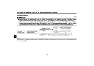
9. Start the engine, and then let it idle
for several minutes while checking
it for oil leakage. If oil is leaking, im-
mediately turn the engine off and
check for the cause.
10. Turn the engine off, and then
check the oil level and correct it if
necessary.
EAU20070
Coolant
The coolant level should be checked
before each ride. In addition, the cool-
ant must be changed at the intervals
specified in the periodic maintenance
and lubrication chart.
EAU20252
To check the coolant level
1. Place the vehicle on a level sur-
face and hold it in an upright posi-
tion.
NOTE:
�
The coolant level must be checked
on a cold engine since the level
varies with engine temperature.
�
Make sure that the vehicle is posi-
tioned straight up when checking
the coolant level. A slight tilt to the
side can result in a false reading.
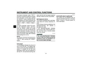
2. Check the coolant level in the cool-
ant reservoir.
NOTE:
The coolant should be between the
minimum and maximum level marks.
Recommended engine oil:
See page 8-1.
Oil quantity:
Without oil filter element replace-
ment:
3.80 L (4.02 US qt) (3.34 Imp.qt)
With oil filter element replacement:
3.90 L (4.12 US qt) (3.43 Imp.qt)
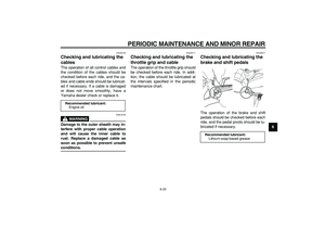
1. “CD” specification
2. “ENERGY CONSERVING II”
1
2
Page 54 of 92
, remove the
reservoir cap, add coolant to th")
PERIODIC MAINTENANCE AND MINOR REPAIR
6-12
1
2
3
4
5
6
7
8
9
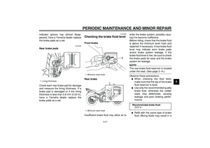
3. If the coolant is at or below the
minimum level mark, remove pan-
el A (See page 6-6.), remove the
reservoir cap, add coolant to the
maximum level mark, and then in-
stall the reservoir cap and the pan-
el.
CAUTION:
ECA10471
�
If coolant is not available, use
distilled water or soft tap water
instead. Do not use hard water
or salt water since it is harmful
to the engine.
�
If water has been used instead
of coolant, replace it with cool-
ant as soon as possible, other-
wise the cooling system will not
be protected against frost and
corrosion.
�
If water has been added to thecoolant, have a Yamaha dealer
check the antifreeze content of
the coolant as soon as possible,
otherwise the effectiveness of
the coolant will be reduced.
WARNING
EWA10380
Never attempt to remove the radiator
cap when the engine is hot.
NOTE:
�
The radiator fan is automatically
switched on or off according to the
coolant temperature in the radia-
tor.
�
If the engine overheats, see page
6-35 for further instructions.
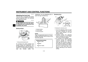
1. Maximum level mark
2. Coolant reservoir
3. Minimum level mark
3 1
2
1. Coolant reservoir cap
Coolant reservoir capacity (up to the
maximum level mark):
0.25 L (0.26 US qt) (0.22 Imp.qt)
1
Page 55 of 92

PERIODIC MAINTENANCE AND MINOR REPAIR
6-13
2
3
4
5
67
8
9
EAU42350
Replacing the air filter element
The air filter element should be re-
placed at the intervals specified in the
periodic maintenance and lubrication
chart. Replace the air filter element
more frequently if you are riding in un-
usually wet or dusty areas.
1. Remove the seat. (See
page 3-14.)
2. Remove cowlings A and B as well
as panels A and B. (See
page 6-6.)
3. Remove the fuel tank bolts.
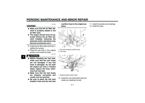
4. Remove the rear brake fluid reser-
voir holder by removing the bolt,
and then lift the fuel tank awayfrom the air filter case. (Do not dis-
connect the fuel hoses!)
WARNING
EWA10410
�
Make sure that the fuel tank is
well supported.
�
Do not tilt or pull the fuel tank
too much, otherwise the fuel
hoses may come loose, which
could cause fuel leakage.
5. Remove the air filter case cover by
removing the screws.6. Pull the air filter element out.
7. Insert a new air filter element into
the air filter case.
1. Bolt
1
1. Rear brake fluid reservoir holder
2. Rear brake fluid reservoir
3. Bolt
12
3
1. Air filter case cover
2. Screw
1. Air filter element
1 2
2 21
Page 56 of 92

PERIODIC MAINTENANCE AND MINOR REPAIR
6-14
1
2
3
4
5
6
7
8
9
CAUTION:
ECA10480
�
Make sure that the air filter ele-
ment is properly seated in the
air filter case.
�
The engine should never be op-
erated without the air filter ele-
ment installed, otherwise the
piston(s) and/or cylinder(s) may
become excessively worn.
8. Install the air filter case cover by in-
stalling the screws.
9. Place the fuel tank in the original
position and install the bolts.
WARNING
EWA11330
�
Before installing the fuel tank,
make sure that the fuel hoses
are not damaged. If any fuel
hose is damaged, do not start
the engine but have a Yamaha
dealer replace the hose, other-
wise fuel may leak.
�
Make sure that the fuel hoses
are properly connected and
routed, and not pinched.
�
Be sure to place the fuel tank
breather hose and the fuel tankoverflow hose in the original po-
sition.
10. Install the rear brake fluid reservoir
holder by installing the bolt.11. Install the panels and cowlings.
12. Install the seat.
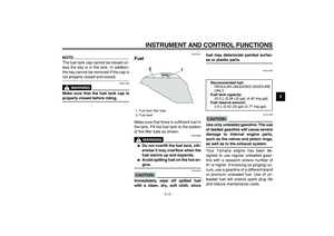
1. Fuel tank breather/overflow hose
2. Fuel hose
1. Original position (paint mark)
12
1