Page 49 of 98
![YAMAHA MAJESTY 400 2008 Owners Manual
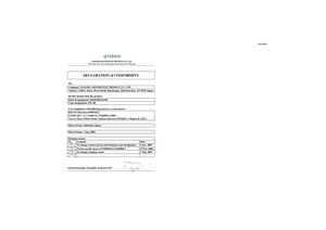
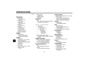
PERIODIC MAINTENANCE AND MINOR REPAIR
6-5
2
3
4
5
67
8
9
22
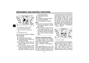
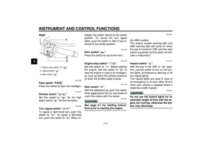
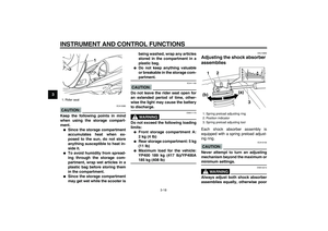
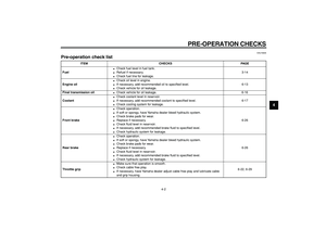
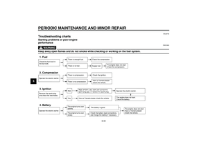
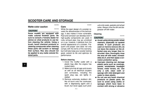
Engine oil
�
Change. (See pages 3-5 and
6-13.)
√
When the oil change indicator flashes [every 5000 km (3000 mi)]
�
Check](/manual-img/51/50635/w960_50635-48.png "YAMAHA MAJESTY 400 2008 Owners Manual
PERIODIC MAINTENANCE AND MINOR REPAIR
6-5
2
3
4
5
67
8
9
22
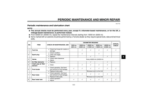
Engine oil
�
Change. (See pages 3-5 and
6-13.)
√
When the oil change indicator flashes [every 5000 km (3000 mi)]
�
Check")
PERIODIC MAINTENANCE AND MINOR REPAIR
6-5
2
3
4
5
67
8
9
22
Engine oil
�
Change. (See pages 3-5 and
6-13.)
√
When the oil change indicator flashes [every 5000 km (3000 mi)]
�
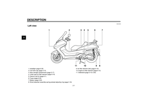
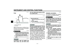
Check oil level and vehicle for
oil leakage.Every 5000 km (3000 mi)
√
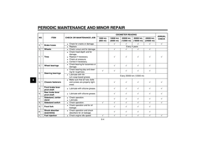
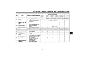
23
Engine oil filter ele-
ment
�
Replace.
√√√
24
*
Cooling system
�
Check coolant level and vehi-
cle for coolant leakage.
√√√√√
�
Change. Every 3 years
25
Final transmission
oil
�
Check vehicle for oil leakage.
√√ √
�
Change.
√√√√√√
26
*
V-belt
�
Replace. When the V-belt replacement indicator flashes [every 20000 km (12000 mi)]
27
*
Front and rear brake
switches
�
Check operation.
√√√√√√
28
Moving parts and
cables
�
Lubricate.
√√√√√
29
*
Throttle grip hous-
ing and cable
�
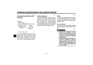
Check operation and free play.
�
Adjust the throttle cable free
play if necessary.
�
Lubricate the throttle grip
housing and cable.
√√√√√
30
*
Lights, signals and
switches
�
Check operation.
�
Adjust headlight beam.
√√√√√√
NO. ITEM CHECK OR MAINTENANCE JOBODOMETER READING
ANNUAL
CHECK 1000 km
(600 mi)10000 km
(6000 mi)20000 km
(12000 mi)30000 km
(18000 mi)40000 km
(24000 mi)
Page 50 of 98
PERIODIC MAINTENANCE AND MINOR REPAIR
6-6
1
2
3
4
5
6
7
8
9
EAU34490
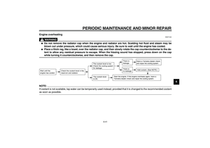
NOTE:
�
The air filters and V-belt filter need more frequent service if you are riding in unusually wet or dusty areas.
�
Hydraulic brake service
�
Regularly check and, if necessary, correct the brake fluid level.
�
Every two years replace the internal components of the brake master cylinders and calipers, and change the brake
fluid.
�
Replace the brake hoses every four years and if cracked or damaged.
Page 51 of 98

PERIODIC MAINTENANCE AND MINOR REPAIR
6-7
2
3
4
5
67
8
9
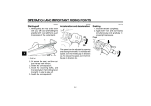
EAU18712
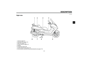
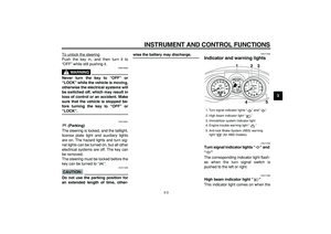
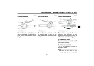
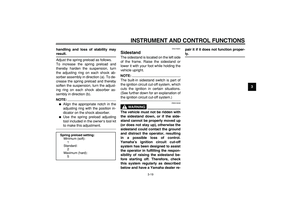
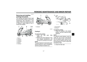
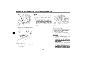
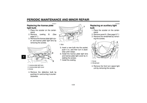
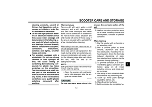
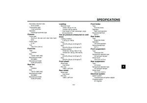
Removing and installing
cowlings and panels
The cowlings and panels shown need
to be removed to perform some of the
maintenance jobs described in this
chapter. Refer to this section each time
a cowling or panel needs to be re-
moved and installed.
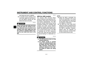
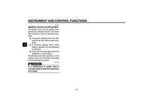
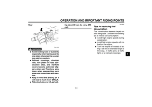
EAU34282
Cowling A
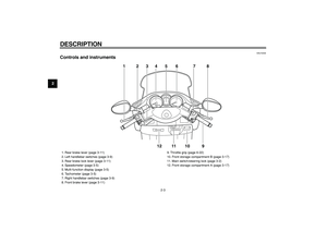
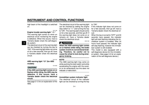
To remove the cowling
1. Open the rider seat. (See
page 3-15.)
2. Remove the quick fasteners in the
rear storage compartment, and
then pull the cowling off as shown.NOTE:
The quick fastener is removed by push-
ing the center pin in with a screwdriver,
and then pulling the fastener out.To install the cowling
1. Place the cowling in the original
position, and then install the quick
fasteners.NOTE:
To install the quick fastener, push the
center pin out so that it will protrude
from the fastener head, insert the fas-
tener into the cowling, and then push
the protruding pin in until it is flush with
the fastener head.
2. Close the rider seat.
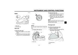
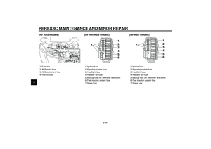
1. Panel A
2. Cowling C
3. Cowling A
4. Cowling B
5. Panel B
6. Cowling E
2
3
4
5
6 1
1. Cowling D
1
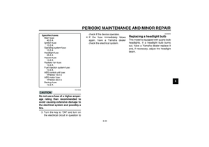
1. Quick fastener
2. Cowling A
1
2
Page 52 of 98
PERIODIC MAINTENANCE AND MINOR REPAIR
6-8
1
2
3
4
5
6
7
8
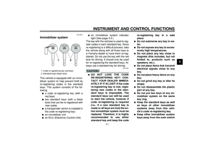
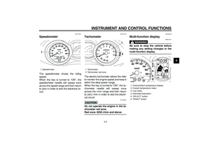
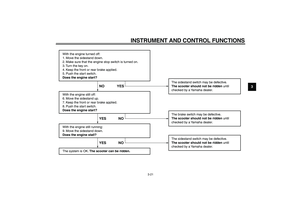
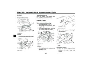
9Cowling B
To remove the cowling
1. Remove the screws.
2. Remove the cowling as shown.To install the cowling
Place the cowling in the original posi-
tion, and then install the screws.
Cowlings C and D
To remove one of the cowlings1. Remove cowlings A and B.
2. Remove the passenger seat. (See
page 3-15.)
3. Remove the grab bar by removing
the grab bar bolts and collars.
4. Remove the screw access cover
by pulling it off.5. Remove the screws, and then pull
the cowling off.
To install the cowling
1. Place the cowling in the original
position, and then install the
screws.
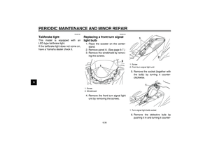
1. Cowling B
2. Screw
1. Cowling B
1
21
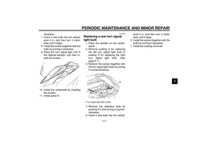
1. Grab bar bolt
2. Collar
3. Grab bar1
1
3
1
1
2
2
22
1. Screw access cover
1. Screw
1
1
1
Page 53 of 98
PERIODIC MAINTENANCE AND MINOR REPAIR
6-9
2
3
4
5
67
8
9
2. Install the screw access cover by
placing it in its original position.
3. Install the grab bar by installing the
collars and grab bar bolts.
4. Install the passenger seat.
5. Install cowlings A and B.
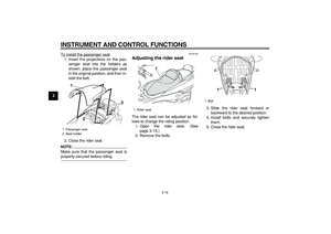
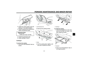
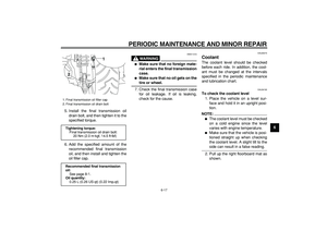
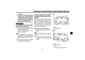
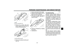
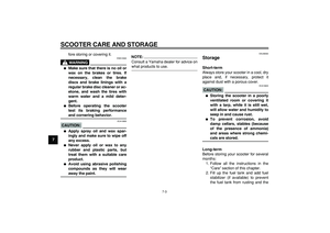
Cowling E
To remove the cowling
1. Pull up the left floorboard mats as
shown.2. Remove the cowling screws.
3. Pull the cowling down slightly, and
then pull it outward as shown.To install the cowling
1. Insert the projections on the cowl-
ing into the slots as shown, and
then install the screws.
2. Place the left floorboard mats in
the original position.
Tightening torque:
Grab bar bolt:
23 Nm (2.3 m·kgf, 16.6 ft·lbf)
1. Left floorboard mat
1. Screw
1
1
1. Cowling E
1. Projection
1
1
1
Page 54 of 98
PERIODIC MAINTENANCE AND MINOR REPAIR
6-10
1
2
3
4
5
6
7
8
9
EAU34290
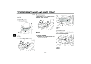
Panel A
To remove the panel
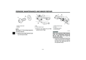
1. Remove the bolts.
2. Pull the panel out as shown.To install the panel
Place the panel in the original position,
and then install the bolts.
Panel B
To remove the panel1. Remove the screws, and then pull
the panel outward.To install the panel
Place the panel in the original position,
and then install the screws.
1. Bolt
2. Panel A
2
1
1. Panel B
2. Screw
1. Screw
2. Panel B
21
12
Page 55 of 98

PERIODIC MAINTENANCE AND MINOR REPAIR
6-11
2
3
4
5
67
8
9
EAU34172
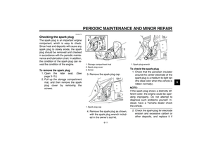
Checking the spark plug
The spark plug is an important engine
component, which is easy to check.
Since heat and deposits will cause any
spark plug to slowly erode, the spark
plug should be removed and checked
in accordance with the periodic mainte-
nance and lubrication chart. In addition,
the condition of the spark plug can re-
veal the condition of the engine.
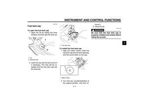
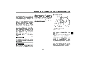
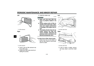
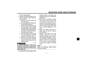
To remove the spark plug
1. Open the rider seat. (See
page 3-15.)
2. Pull up the storage compartment
mat, and then remove the spark
plug cover by removing the
screws.3. Remove the spark plug cap.
4. Remove the spark plug as shown,
with the spark plug wrench includ-
ed in the owner’s tool kit.
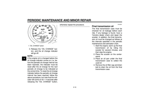
To check the spark plug
1. Check that the porcelain insulator
around the center electrode of the
spark plug is a medium-to-light tan
(the ideal color when the vehicle is
ridden normally).
NOTE:
If the spark plug shows a distinctly dif-
ferent color, the engine could be oper-
ating improperly. Do not attempt to
diagnose such problems yourself. In-
stead, have a Yamaha dealer check
the vehicle.
2. Check the spark plug for electrode
erosion and excessive carbon or
other deposits, and replace it if
1. Storage compartment mat
2. Spark plug cover
3. Screw
1. Spark plug cap
1
2
3
1
1. Spark plug wrench
1
Page 56 of 98

PERIODIC MAINTENANCE AND MINOR REPAIR
6-12
1
2
3
4
5
6
7
8
9
necessary.
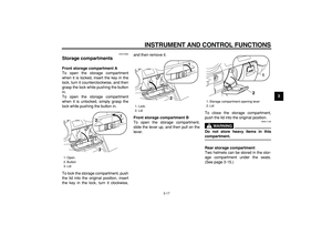
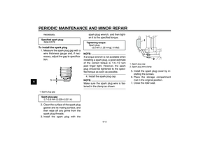
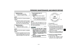
To install the spark plug
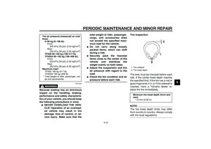
1. Measure the spark plug gap with a
wire thickness gauge and, if nec-
essary, adjust the gap to specifica-
tion.
2. Clean the surface of the spark plug
gasket and its mating surface, and
then wipe off any grime from the
spark plug threads.
3. Install the spark plug with thespark plug wrench, and then tight-
en it to the specified torque.
NOTE:
If a torque wrench is not available when
installing a spark plug, a good estimate
of the correct torque is 1/4–1/2 turn
past finger tight. However, the spark
plug should be tightened to the speci-
fied torque as soon as possible.
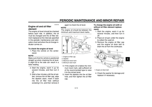
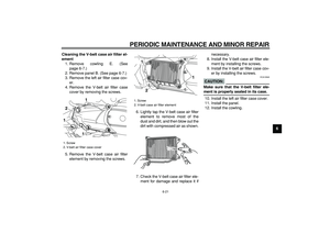
4. Install the spark plug cap.
NOTE:
Make sure the spark plug wire is fas-
tened in the clamp as shown.5. Install the spark plug cover by in-
stalling the screws.
6. Place the storage compartment
mat in the original position.
7. Close the rider seat.
Specified spark plug:
NGK/CR7E
1. Spark plug gap
Spark plug gap:
0.7–0.8 mm (0.028–0.031 in)
1
Tightening torque:
Spark plug:
12.5 Nm (1.25 m·kgf, 9 ft·lbf)
1. Spark plug cap
2. Spark plug wire clamp
1
2