Page 89 of 98

SCOOTER CARE AND STORAGE
7-4
2
3
4
5
6
78
9
fuel from deteriorating.
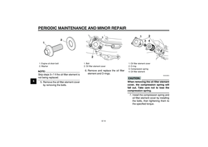
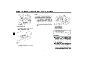
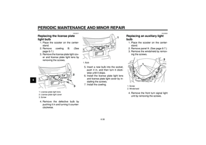
3. Perform the following steps to pro-
tect the cylinder, piston rings, etc.
from corrosion.
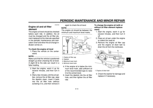
a. Remove the spark plug cap
and spark plug.
b. Pour a teaspoonful of engine oil
into the spark plug bore.
c. Install the spark plug cap onto
the spark plug, and then place
the spark plug on the cylinder
head so that the electrodes are
grounded. (This will limit spark-
ing during the next step.)
d. Turn the engine over several
times with the starter. (This will
coat the cylinder wall with oil.)
e. Remove the spark plug cap
from the spark plug, and then
install the spark plug and the
spark plug cap.
WARNING
EWA10950
To prevent damage or injury from
sparking, make sure to ground the
spark plug electrodes while turning
the engine over.
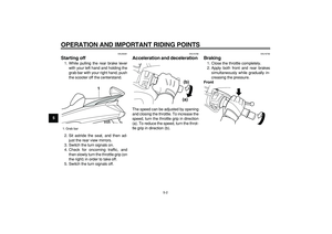
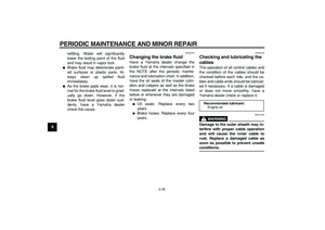
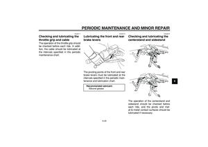
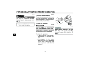
4. Lubricate all control cables and thepivoting points of all levers and
pedals as well as of the sidestand/
centerstand.
5. Check and, if necessary, correct
the tire air pressure, and then lift
the scooter so that both of its
wheels are off the ground. Alterna-
tively, turn the wheels a little every
month in order to prevent the tires
from becoming degraded in one
spot.
6. Cover the muffler outlet with a
plastic bag to prevent moisture
from entering it.
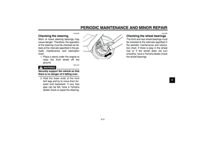
7. Remove the battery and fully
charge it. Store it in a cool, dry
place and charge it once a month.
Do not store the battery in an ex-
cessively cold or warm place [less
than 0 °C (30 °F) or more than 30
°C (90 °F)]. For more information
on storing the battery, see page
6-32.
NOTE:
Make any necessary repairs before
storing the scooter.
Page 90 of 98

Overall width:
780 mm (30.7 in)
Overall height:
1380 mm (54.3 in)
Seat height:
760 mm (29.9 in)")
8-1
1
2
3
4
5
6
7
8
9
SPECIFICATIONS
EAU2633M
Dimensions:
Overall length:
2230 mm (87.8 in)
Overall width:
780 mm (30.7 in)
Overall height:
1380 mm (54.3 in)
Seat height:
760 mm (29.9 in)
Wheelbase:
1565 mm (61.6 in)
Ground clearance:
120 mm (4.72 in)
Minimum turning radius:
2600 mm (102.4 in)
Weight:
With oil and fuel:
YP400 219.0 kg (483 lb)
YP400A 223.0 kg (492 lb)
Engine:
Engine type:
Liquid cooled 4-stroke, DOHC
Cylinder arrangement:
Forward-inclined single cylinder
Displacement:
395.0 cm
3
Bore
×
stroke:
83.0
×
73.0 mm (3.27
×
2.87 in)
Compression ratio:
10.60 :1Starting system:
Electric starter
Lubrication system:
Wet sump
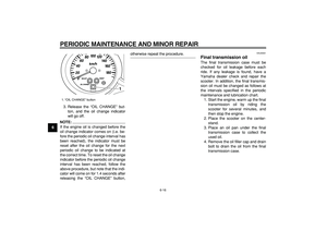
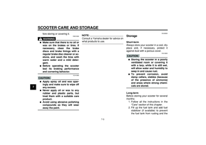
Engine oil:
Type:
SAE 10W-30, SAE 10W-40, SAE 15W-40,
SAE 20W-40 or SAE 20W-50
Recommended engine oil grade:
API service SG type or higher, JASO stan-
dard MA
Engine oil quantity:
Without oil filter element replacement:
1.50 L (1.59 US qt) (1.32 Imp.qt)
With oil filter element replacement:
1.70 L (1.80 US qt) (1.50 Imp.qt)
Final transmission oil:
Type:
SAE 10W-30 type SE motor oil
Quantity:
0.25 L (0.26 US qt) (0.22 Imp.qt)
Cooling system:
Coolant reservoir capacity (up to the maxi-
mum level mark):
0.32 L (0.34 US qt) (0.28 Imp.qt)
Radiator capacity (including all routes):
1.57 L (1.66 US qt) (1.38 Imp.qt)
Air filter:
Air filter element:
Oil-coated paper element
Fuel:
Recommended fuel:
Regular unleaded gasoline only
Fuel tank capacity:
14.0 L (3.70 US gal) (3.08 Imp.gal)
Fuel injection:
Throttle body:
Manufacturer:
AISAN
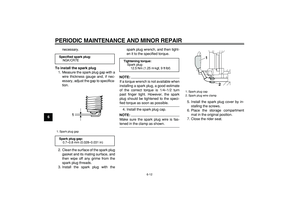
Spark plug (s):
Manufacturer/model:
NGK/CR7E
Spark plug gap:
0.7–0.8 mm (0.028–0.031 in)
Clutch:
Clutch type:
Dry, centrifugal automatic
Transmission:
Primary reduction system:
Helical gear
Primary reduction ratio:
31/14 (2.214)
Secondary reduction system:
Helical gear
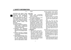
-20 -10 0
10 20 30
40
50 ˚C
SAE 10W-30
SAE 15W-40SAE 20W-40SAE 20W-50
SAE 10W-40SAE 10W-50
Page 91 of 98

Transmission type:
V-belt automatic
Operation:
Centrifugal automatic type
Chassis:
Frame type:
Aluminum die-cast")
SPECIFICATIONS
8-2
2
3
4
5
6
7
89
Secondary reduction ratio:
42/16 (2.625)
Transmission type:
V-belt automatic
Operation:
Centrifugal automatic type
Chassis:
Frame type:
Aluminum die-cast and steel tube back-
bone
Caster angle:
27.00 °
Trail:
100.0 mm (3.94 in)
Front tire:
Type:
Tubeless
Size:
120/80-14M/C 58S
Manufacturer/model:
IRC/MB67
Manufacturer/model:
DUNLOP/D305FL
Rear tire:
Type:
Tubeless
Size:
150/70-13M/C 64S
Manufacturer/model:
IRC/MB67
Manufacturer/model:
DUNLOP/D305L
Loading:
Maximum load:
YP400 189 kg (417 lb)
YP400A 185 kg (408 lb)
* (Total weight of rider, passenger, cargo
and accessories)
Tire air pressure (measured on cold
tires):
Loading condition:
0–90 kg (0–198 lb)
Front:
200 kPa (29 psi) (2.00 kgf/cm
2
)
Rear:
250 kPa (36 psi) (2.50 kgf/cm
2
)
Loading condition:
YP400 90–189 kg (198–417 lb)
YP400A 90–185 kg (198–408 lb)
Front:
200 kPa (29 psi) (2.00 kgf/cm
2
)
Rear:
250 kPa (36 psi) (2.50 kgf/cm
2
)
Front wheel:
Wheel type:
Cast wheel
Rim size:
14M/C x MT3.00
Rear wheel:
Wheel type:
Cast wheel
Rim size:
13M/C x MT4.00
Front brake:
Type:
Dual disc brake
Operation:
Right hand operation
Recommended fluid:
DOT 4
Rear brake:
Type:
Single disc brake
Operation:
Left hand operation
Recommended fluid:
DOT 4
Front suspension:
Type:
Telescopic fork
Spring/shock absorber type:
Coil spring/oil damper
Wheel travel:
120.0 mm (4.72 in)
Rear suspension:
Type:
Unit swing
Spring/shock absorber type:
Coil spring/oil damper
Wheel travel:
104.0 mm (4.09 in)
Electrical system:
Ignition system:
Transistorized coil ignition (digital)
Charging system:
AC magneto
Page 92 of 98
SPECIFICATIONS
8-3
1
2
3
4
5
6
7
8
9Battery:
Model:
GT9B-4
Voltage, capacity:
12 V, 8.0 Ah
Headlight:
Bulb type:
Halogen bulb
Bulb voltage, wattage
×
quantity:
Headlight:
12 V, 60 W/55.0 W
×
2
Tail/brake light:
LED
Front turn signal light:
12 V, 21.0 W
×
2
Rear turn signal light:
12 V, 21.0 W
×
2
Auxiliary light:
12 V, 5.0 W
×
2
License plate light:
12 V, 5.0 W
×
1
Meter lighting:
12 V, 2.0 W
×
3
High beam indicator light:
12 V, 1.4 W
×
1
Turn signal indicator light:
12 V, 1.4 W
×
2
Engine trouble warning light:
12 V, 1.4 W
×
1
ABS warning light:
YP400A 12 V, 1.4 W
×
1
Immobilizer system indicator light:
LED
Fuses:
Main fuse:
40.0 A
Headlight fuse:
25.0 A
Signaling system fuse:
10.0 A
Ignition fuse:
10.0 A
Radiator fan fuse:
10.0 A
Hazard fuse:
10.0 A
Fuel injection system fuse:
10.0 A
ABS control unit fuse:
YP400A 10.0 A
ABS motor fuse:
YP400A 30.0 A
Backup fuse:
10.0 A
Page 93 of 98
9-1
2
3
4
5
6
7
8
9
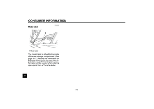
CONSUMER INFORMATION
EAU26351
Identification numbers
Record the key identification number,
vehicle identification number and mod-
el label information in the spaces pro-
vided below for assistance when
ordering spare parts from a Yamaha
dealer or for reference in case the vehi-
cle is stolen.
KEY IDENTIFICATION NUMBER:
VEHICLE IDENTIFICATION
NUMBER:
MODEL LABEL INFORMATION:
EAU26381
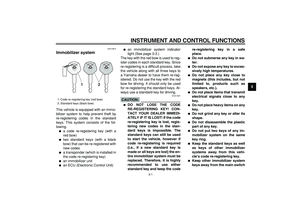
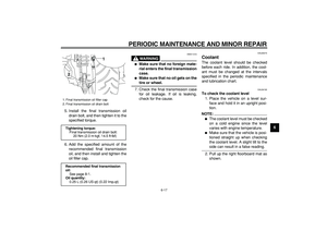
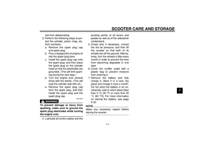
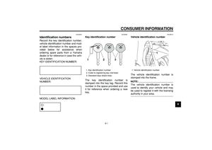
Key identification number
The key identification number is
stamped into the key tag. Record this
number in the space provided and use
it for reference when ordering a new
key.
EAU26410
Vehicle identification number
The vehicle identification number is
stamped into the frame.
NOTE:
The vehicle identification number is
used to identify your vehicle and may
be used to register it with the licensing
authority in your area.
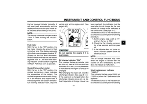
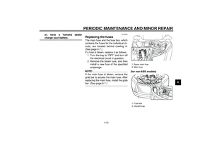
1. Key identification number
2. Code re-registering key (red bow)
3. Standard keys (black bow)
1. Vehicle identification number
1
Page 94 of 98
CONSUMER INFORMATION
9-2
1
2
3
4
5
6
7
8
9
EAU26500
Model label
The model label is affixed to the inside
of the rear storage compartment. (See
page 3-17.) Record the information on
this label in the space provided. This in-
formation will be needed when ordering
spare parts from a Yamaha dealer.
1. Model label
1
Page 95 of 98
 .............................3-12
ABS warning light (for ABS models) ..........3-4
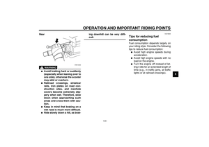
Acceleration and deceleration ...................5-2
Air filter elements and check h")
INDEX
A
ABS (for ABS models) .............................3-12
ABS warning light (for ABS models) ..........3-4
Acceleration and deceleration ...................5-2
Air filter elements and check hoses and
V-belt case air filter element ..................6-19
Anti-theft alarm (optional) ..........................3-9
Auxiliary light bulb, replacing ...................6-38
B
Battery .....................................................6-32
Brake fluid, changing ...............................6-28
Brake fluid level, checking .......................6-27
Brake lever, front .....................................3-11
Brake lever, rear ......................................3-11
Brake levers, lubricating ..........................6-29
Braking ......................................................5-2
C
Cables, checking and lubricating .............6-28
Care ...........................................................7-1
Catalytic converters .................................3-14
Centerstand and sidestand, checking and
lubricating ..............................................6-29
Coolant ....................................................6-17
Cowlings and panels, removing and
installing ..................................................6-7
D
Dimmer switch .........................................3-10
E
Engine break-in .........................................5-4
Engine oil and oil filter element ................6-13
Engine stop switch...................................3-10
Engine trouble warning light ......................3-4
F
Final transmission oil ...............................6-16Front and rear brake lever free play ........ 6-25
Front and rear brake pads, checking....... 6-26
Front fork, checking ................................. 6-30
Fuel ......................................................... 3-14
Fuel consumption, tips for reducing .......... 5-3
Fuel tank cap ........................................... 3-13
Fuses, replacing ...................................... 6-33
H
Handlebar switches ................................... 3-9
Hazard switch .......................................... 3-10
Headlight bulb, replacing ......................... 6-35
High beam indicator light ........................... 3-3
Horn switch.............................................. 3-10
I
Identification numbers ............................... 9-1
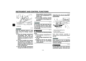
Ignition circuit cut-off system ................... 3-20
Immobilizer system.................................... 3-1
Immobilizer system indicator light ............. 3-4
Indicator and warning lights....................... 3-3
K
Key identification number .......................... 9-1
L
License plate light bulb, replacing ........... 6-38
M
Main switch/steering lock .......................... 3-2
Matte color, caution ................................... 7-1
Model label ................................................ 9-2
Multi-function display ................................. 3-5
P
Parking ...................................................... 5-4
Part locations............................................. 2-1
Pass switch ............................................. 3-10
Periodic maintenance and lubrication
chart ........................................................ 6-3Pre-operation check list............................. 4-2
R
Rear brake lock lever .............................. 3-11
Rear brake lock lever cable, adjusting .... 6-26
Rider seat, adjusting ............................... 3-16
S
Safe-riding points ...................................... 1-4
Safety information ..................................... 1-1
Seats ....................................................... 3-15
Shock absorber assemblies, adjusting.... 3-18
Sidestand ................................................ 3-19
Spark plug, checking ............................... 6-11
Specifications ............................................ 8-1
Speedometer............................................. 3-5
Starting off ................................................. 5-2
Starting the engine .................................... 5-1
Start switch.............................................. 3-10
Steering, checking................................... 6-31
Storage...................................................... 7-3
Storage compartments ............................ 3-17
T
Tachometer ............................................... 3-5
Tail/brake light ......................................... 6-36
Throttle cable free play, checking ........... 6-22
Throttle grip and cable, checking and
lubricating ............................................. 6-29
Tires ........................................................ 6-22
Tool kit....................................................... 6-1
Troubleshooting ...................................... 6-39
Troubleshooting charts............................ 6-40
Turn signal indicator lights ........................ 3-3
Turn signal light bulb (front), replacing .... 6-36
Turn signal light bulb (rear), replacing..... 6-37
Turn signal switch ................................... 3-10
Page 96 of 98
INDEX
V
Valve clearance ...................................... 6-22
Vehicle identification number .................... 9-1
W
Wheel bearings, checking ....................... 6-31
Wheels .................................................... 6-24


 Record the information on
this label")
