Page 57 of 98

PERIODIC MAINTENANCE AND MINOR REPAIR
6-13
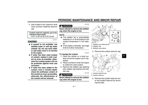
6 the coolant as soon as possible,
otherwise the effectiveness of
the coolant will be reduced.
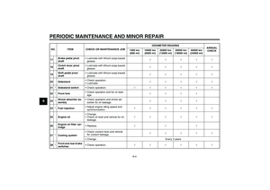
12. Install the coolant reservoir cap.
13. Install the radiator cap, radiator
cap retainer and radiator cap re-
taining bolt.
14. Start the engine, let it idle for sev-
eral minutes, and then turn it off.
15. Remove the radiator cap to check
the coolant level in the radiator. If
necessary, add sufficient coolant
until it reaches the top of the radia-
tor, and then install the radiator
cap, radiator cap retainer and radi-
ator cap retaining bolt.16. Check the coolant level in the res-
ervoir. If necessary, remove the
coolant reservoir cap, add coolant
to the maximum level mark, and
then install the cap.
17. Start the engine, and then check
the vehicle for coolant leakage. If
coolant is leaking, have a Yamaha
dealer check the cooling system.
EAU34424
Replacing the air filter element The air filter element should be re-
placed at the intervals specified in the
periodic maintenance and lubrication
chart. Replace the air filter element
more frequently if you are riding in un-
usually wet or dusty areas.
1. Remove the seat. (See page
3-18.)
2. Remove the fuel tank bolts, and
then lift the fuel tank away from the
air filter case.
3. Remove the air filter case cover by
removing the screws.
1. Radiator cap retaining bolt
2. Radiator cap
3. Radiator cap retainer
1. Bolt
U5S5E1E0.book Page 13 Friday, June 22, 2007 1:03 PM
Page 58 of 98

PERIODIC MAINTENANCE AND MINOR REPAIR
6-14
6
CAUTION:
ECA12880
When removing the air filter case
cover, be careful not to allow foreign
objects to drop into the air intakemanifold.
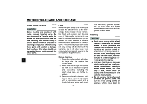
4. Pull the air filter element out.5. Insert a new air filter element into
the air filter case.
CAUTION:
ECA10480
�
Make sure that the air filter ele-
ment is properly seated in the
air filter case.
�
The engine should never be op-
erated without the air filter ele-
ment installed, otherwise the
piston(s) and/or cylinder(s) maybecome excessively worn.
6. Install the air filter case cover by in-
stalling the screws.
7. Place the fuel tank in the original
position and install the bolts.
WARNING
EWA12462
�
Before placing the fuel tank in
the original position, make sure
that all hoses (i.e., fuel hose,
fuel tank breather hose, fuel
tank overflow hose) are not
damaged, that they are properly
connected and routed, and that
they are not pinched.
�
If any hose is damaged, have a
Yamaha dealer replace the hose
before starting the engine, oth-erwise fuel may leak.
1. Screw
2. Air filter case cover
1. Air filter element
2. Air intake manifold
1. Hose
U5S5E1E0.book Page 14 Friday, June 22, 2007 1:03 PM
Page 59 of 98
PERIODIC MAINTENANCE AND MINOR REPAIR
6-15
6
WARNING
EWA12471
Be sure to place the hoses in theiroriginal position as shown.
8. Install the seat.
EAU34301
Adjusting the engine idling
speed The engine idling speed must be
checked and, if necessary, adjusted as
follows at the intervals specified in the
periodic maintenance and lubrication
chart.
The engine should be warm before
making this adjustment.
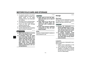
Check the engine idling speed and, if
necessary, adjust it to specification by
turning the idle adjusting screw. To in-
crease the engine idling speed, turn the
screw in direction (a). To decrease the
engine idling speed, turn the screw in
direction (b).
NOTE:If the specified idling speed cannot be
obtained as described above, have aYamaha dealer make the adjustment.
1. Original position (paint mark)
1. Idle adjusting screw
Engine idling speed:
1250–1350 r/min
U5S5E1E0.book Page 15 Friday, June 22, 2007 1:03 PM
Page 60 of 98
 at the
throttle grip. Periodica")
PERIODIC MAINTENANCE AND MINOR REPAIR
6-16
6
EAU21382
Checking the throttle cable
free play The throttle cable free play should mea-
sure 3.0–5.0 mm (0.12–0.20 in) at the
throttle grip. Periodically check the
throttle cable free play and, if neces-
sary, have a Yamaha dealer adjust it.
EAU21401
Valve clearance The valve clearance changes with use,
resulting in improper air-fuel mixture
and/or engine noise. To prevent this
from occurring, the valve clearance
must be adjusted by a Yamaha dealer
at the intervals specified in the periodic
maintenance and lubrication chart.
EAU21771
Tires To maximize the performance, durabil-
ity, and safe operation of your motor-
cycle, note the following points
regarding the specified tires.
Tire air pressure
The tire air pressure should be checked
and, if necessary, adjusted before each
ride.
WARNING
EWA10500
�
The tire air pressure must be
checked and adjusted on cold
tires (i.e., when the temperature
of the tires equals the ambient
temperature).
�
The tire air pressure must be ad-
justed in accordance with the
riding speed and with the total
weight of rider, passenger, car-
go, and accessories approvedfor this model.
1. Throttle cable free playU5S5E1E0.book Page 16 Friday, June 22, 2007 1:03 PM
Page 61 of 98

PERIODIC MAINTENANCE AND MINOR REPAIR
6-17
6
WARNING
EWA11020
Because loading has an enormous
impact on the handling, braking,
performance and safety characteris-
tics of your motorcycle, you should
keep the following precautions in
mind.
�
NEVER OVERLOAD THE
MOTORCYCLE! Operation of an
overloaded motorcycle may re-
sult in tire damage, loss of con-
trol, or severe injury. Make sure
that the total weight of rider,
passenger, cargo, and accesso-
ries does not exceed the speci-
fied maximum load for the
vehicle.
�
Do not carry along loosely
packed items, which can shift
during a ride.
�
Securely pack the heaviest
items close to the center of the
motorcycle and distribute the
weight evenly on both sides.
�
Adjust the suspension and tire
air pressure with regard to the
load.
�
Check the tire condition and airpressure before each ride.Tire inspection
The tires must be checked before each
ride. If the center tread depth reaches
the specified limit, if the tire has a nail or
glass fragments in it, or if the sidewall is
cracked, have a Yamaha dealer re-
place the tire immediately.
NOTE:The tire tread depth limits may differ
from country to country. Always complywith the local regulations.
Tire air pressure (measured on cold
tires):
0–90 kg (0–198 lb):
Front:
225 kPa (33 psi) (2.25 kgf/cm²)
Rear:
250 kPa (36 psi) (2.50 kgf/cm²)
FZ6-NAHG 90–191 kg (198–421 lb)
FZ6-NHG 90–196 kg (198–432 lb):
Front:
250 kPa (36 psi) (2.50 kgf/cm²)
Rear:
290 kPa (42 psi) (2.90 kgf/cm²)
High-speed riding:
Front:
225 kPa (33 psi) (2.25 kgf/cm²)
Rear:
250 kPa (36 psi) (2.50 kgf/cm²)
Maximum load*:
FZ6-NAHG 191 kg (421 lb)
FZ6-NHG 196 kg (432 lb)
* Total weight of rider, passenger, car-
go and accessories
1. Tire sidewall
2. Tire tread depth
Minimum tire tread depth (front and
rear):
1.6 mm (0.06 in)
U5S5E1E0.book Page 17 Friday, June 22, 2007 1:03 PM
Page 62 of 98

PERIODIC MAINTENANCE AND MINOR REPAIR
6-18
6
WARNING
EWA10470
�
Have a Yamaha dealer replace
excessively worn tires. Besides
being illegal, operating the vehi-
cle with excessively worn tires
decreases riding stability and
can lead to loss of control.
�
The replacement of all wheel
and brake related parts, includ-
ing the tires, should be left to a
Yamaha dealer, who has the
necessary professional knowl-edge and experience.
Tire informationThis motorcycle is equipped with cast
wheels and tubeless tires with valves.
WARNING
EWA10480
�
The front and rear tires should
be of the same make and de-
sign, otherwise the handling
characteristics of the motor-
cycle cannot be guaranteed.
�
After extensive tests, only the
tires listed below have been ap-
proved for this model by
Yamaha Motor Co., Ltd.
�
Always make sure that the valve
caps are securely installed to
prevent air pressure leakage.
�
Use only the tire valves and
valve cores listed below to
avoid tire deflation during ahigh-speed ride.
WARNING
EWA10600
This motorcycle is fitted with super-
high-speed tires. Note the following
points in order to make the most ef-
ficient use of these tires.�
Use only the specified replace-
ment tires. Other tires may run
the danger of bursting at super
high speeds.
�
Brand-new tires can have a rela-
tively poor grip on certain road
surfaces until they have been
1. Tire air valve
2. Tire air valve core
3. Tire air valve cap with seal
Front tire:
Size:
120/70 ZR17M/C (58W)
Manufacturer/model:
BRIDGESTONE/BT020F GG
DUNLOP/D252F
Rear tire:
Size:
180/55 ZR17M/C (73W)
Manufacturer/model:
BRIDGESTONE/BT020R GG
DUNLOP/D252
FRONT and REAR:
Tire air valve:
TR412
Va l ve c o r e :
#9100 (original)
U5S5E1E0.book Page 18 Friday, June 22, 2007 1:03 PM
Page 63 of 98
 after installin")
PERIODIC MAINTENANCE AND MINOR REPAIR
6-19
6 “broken in”. Therefore, it is ad-
visable before doing any high-
speed riding to ride conserva-
tively for approximately 100 km
(60 mi) after installing a new tire.
�
The tires must be warmed up
before a high-speed run.
�
Always adjust the tire air pres-
sure according to the operatingconditions.
EAU21960
Cast wheels To maximize the performance, durabil-
ity, and safe operation of your vehicle,
note the following points regarding the
specified wheels.�
The wheel rims should be checked
for cracks, bends or warpage be-
fore each ride. If any damage is
found, have a Yamaha dealer re-
place the wheel. Do not attempt
even the smallest repair to the
wheel. A deformed or cracked
wheel must be replaced.
�
The wheel should be balanced
whenever either the tire or wheel
has been changed or replaced. An
unbalanced wheel can result in
poor performance, adverse han-
dling characteristics, and a short-
ened tire life.
�
Ride at moderate speeds after
changing a tire since the tire sur-
face must first be “broken in” for it
to develop its optimal characteris-
tics.
EAU22080
Adjusting the clutch lever free
play The clutch lever free play should mea-
sure 10.0–15.0 mm (0.39–0.59 in) as
shown. Periodically check the clutch le-
ver free play and, if necessary, adjust it
as follows.
To increase the clutch lever free play,
turn the adjusting bolt in direction (a).
To decrease the clutch lever free play,
turn the adjusting bolt in direction (b).1. Clutch lever free play adjusting bolt
2. Clutch lever free play
U5S5E1E0.book Page 19 Friday, June 22, 2007 1:03 PM
Page 64 of 98

PERIODIC MAINTENANCE AND MINOR REPAIR
6-20
6
NOTE:If the specified free play cannot be ob-
tained as described above or if the
clutch does not operate correctly, have
a Yamaha dealer check the internalclutch mechanism.
EAU36501
Rear brake light switch The rear brake light switch, which is ac-
tivated by the brake pedal, is properly
adjusted when the brake light comes
on just before braking takes effect. If
necessary, have a Yamaha dealer ad-
just the brake light switch.
EAU22390
Checking the front and rear
brake pads The front and rear brake pads must be
checked for wear at the intervals spec-
ified in the periodic maintenance and
lubrication chart.
EAU36890
Front brake pads
Each front brake pad is provided with
wear indicators, which allows you to
check the brake pad wear without hav-
ing to disassemble the brake. To check
the brake pad wear, check the position
of the wear indicators while applying
the brake. If a brake pad has worn to1. Brake pad wear indicator
U5S5E1E0.book Page 20 Friday, June 22, 2007 1:03 PM