Page 25 of 98

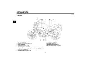
INSTRUMENT AND CONTROL FUNCTIONS
3-11
3
�
When the key is turned to “ON”,
the coolant temperature is auto-
matically displayed, even if the air
intake temperature was displayed
prior to turning the key to “OFF”.
�
When the air intake temperature
display is selected, “A” is displayed
for one second, and then the air in-take temperature is displayed.
Self-diagnosis device
This model is equipped with a self-diag-
nosis device for various electrical cir-
cuits.If any of those circuits are defective, the
engine trouble warning light will come
on, and then the display will indicate a
two-digit error code.
This model is also equipped with a self-
diagnosis device for the immobilizer
system.
If any of the immobilizer system circuits
are defective, the immobilizer system
indicator light will flash, and then the
display will indicate a two-digit error
code.
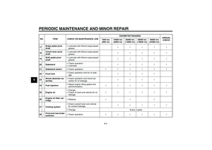
NOTE:If the display indicates error code 52,
this could be caused by transponder in-
terference. If this error code appears,try the following.
1. Use the code re-registering key to
start the engine.NOTE:Make sure there are no other immobi-
lizer keys close to the main switch, and
do not keep more than one immobilizer
key on the same key ring! Immobilizer
system keys may cause signal interfer-
ence, which may prevent the enginefrom starting.2. If the engine starts, turn it off and
try starting the engine with the
standard keys.
3. If one or both of the standard keys
do not start the engine, take the
vehicle, the code re-registering
key and both standard keys to a
Yamaha dealer and have the stan-
dard keys re-registered.
If the display indicates any error codes,
note the code number, and then have a
Yamaha dealer check the vehicle.
CAUTION:
ECA11590
If the display indicates an error
code, the vehicle should be checked
as soon as possible in order to avoidengine damage.
1. Error code display
U5S5E1E0.book Page 11 Friday, June 22, 2007 1:03 PM
Page 26 of 98
INSTRUMENT AND CONTROL FUNCTIONS
3-12
3LCD and tachometer brightness
control mode
This function allows you to adjust the
brightness of the LCD and the tachom-
eter panel and needle to suit the out-
side lighting conditions.
To set the brightness
1. Turn the key to “OFF”.
2. Push and hold the “SELECT” but-
ton.
3. Turn the key to “ON”, and then re-
lease the “SELECT” button after
five seconds.4. Push the “RESET” button to select
the desired brightness level.
5. Push the “SELECT” button to con-
firm the selected brightness level.
The display will return to the odom-
eter or tripmeter mode.
EAU12331
Anti-theft alarm (optional) This model can be equipped with an
optional anti-theft alarm by a Yamaha
dealer. Contact a Yamaha dealer for
more information.
1. Tachometer panel
2. Tachometer needle
3. LCD
4. Brightness levelU5S5E1E0.book Page 12 Friday, June 22, 2007 1:03 PM
Page 27 of 98

INSTRUMENT AND CONTROL FUNCTIONS
3-13
3
EAU12347
Handlebar switches LeftRight
EAU12350
Pass switch“”
Press this switch to flash the headlight.
EAU12400
Dimmer switch“/”
Set this switch to“” for the high
beam and to“” for the low beam.
EAU12460
Turn signal switch“/”
To signal a right-hand turn, push this
switch to“”. To signal a left-hand
turn, push this switch to“”. When re-
leased, the switch returns to the centerposition. To cancel the turn signal
lights, push the switch in after it has re-
turned to the center position.
EAU12500
Horn switch“”
Press this switch to sound the horn.
EAU12660
Engine stop switch“/”
Set this switch to“” before starting
the engine. Set this switch to“” to
stop the engine in case of an emergen-
cy, such as when the vehicle overturns
or when the throttle cable is stuck.
EAU12710
Start switch“”
Push this switch to crank the engine
with the starter.CAUTION:
ECA10050
See page 5-1 for starting instruc-tions prior to starting the engine.
1. Pass switch“”
2. Dimmer switch“/”
3. Turn signal switch“/”
4. Horn switch“”
5. Hazard switch“”
1. Engine stop switch“/”
2. Start switch“”
U5S5E1E0.book Page 13 Friday, June 22, 2007 1:03 PM
Page 28 of 98
 will
come on when the key is turned to “ON”
and the start switch is pushed,")
INSTRUMENT AND CONTROL FUNCTIONS
3-14
3
EAU44710
The engine trouble warning light and
ABS warning light (ABS model only) will
come on when the key is turned to “ON”
and the start switch is pushed, but this
does not indicate a malfunction.
EAU12733
Hazard switch“”
With the key in the “ON” or“” posi-
tion, use this switch to turn on the haz-
ard lights (simultaneous flashing of all
turn signal lights).
The hazard lights are used in case of
an emergency or to warn other drivers
when your vehicle is stopped where it
might be a traffic hazard.CAUTION:
ECA10061
Do not use the hazard lights for an
extended length of time with the en-
gine not running, otherwise the bat-tery may discharge.
EAU12820
Clutch lever The clutch lever is located at the left
handlebar grip. To disengage the
clutch, pull the lever toward the handle-
bar grip. To engage the clutch, release
the lever. The lever should be pulled
rapidly and released slowly for smooth
clutch operation.
The clutch lever is equipped with a
clutch switch, which is part of the igni-
tion circuit cut-off system. (See page
3-22.)
EAU12870
Shift pedal The shift pedal is located on the left
side of the engine and is used in com-
bination with the clutch lever when
shifting the gears of the 6-speed con-
stant-mesh transmission equipped on
this motorcycle.
1. Clutch lever
1. Shift pedal
U5S5E1E0.book Page 14 Friday, June 22, 2007 1:03 PM
Page 29 of 98

INSTRUMENT AND CONTROL FUNCTIONS
3-15
3
EAU26822
Brake lever The brake lever is located at the right
handlebar grip. To apply the front
brake, pull the lever toward the handle-
bar grip.
The brake lever is equipped with a po-
sition adjusting dial. To adjust the dis-
tance between the brake lever and the
handlebar grip, turn the adjusting dial
while holding the lever pushed away
from the handlebar grip. Make sure that
the appropriate setting on the adjusting
dial is aligned with the“” m ar k on the
brake lever.
EAU12941
Brake pedal The brake pedal is on the right side of
the motorcycle. To apply the rear
brake, press down on the brake pedal.
EAU26792
ABS (for ABS models) The Yamaha ABS (Anti-lock Brake
System) features a dual electronic con-
trol system, which acts on the front and
rear brakes independently. The ABS is
monitored by an ECU (Electronic Con-
trol Unit), which will have recourse to
manual braking if a malfunction occurs.
WARNING
EWA10090
�
The ABS performs best on long
braking distances.
�
On certain (rough or gravel)
roads, the braking distance may
be longer with than without the
ABS. Therefore, always keep a
sufficient distance to the vehicle
ahead to match the ridingspeed.
NOTE:�
When the ABS is activated, the
brakes are operated in the usual
way. A pulsating action may be felt
at the brake lever or brake pedal,
but this does not indicate a mal-
function.
1. Brake lever
2. Brake lever position adjusting dial
3.“” mark
4. Distance between brake lever and handlebar
grip
1. Brake pedal
U5S5E1E0.book Page 15 Friday, June 22, 2007 1:03 PM
Page 30 of 98

INSTRUMENT AND CONTROL FUNCTIONS
3-16
3
�
This ABS has a test mode which
allows the owner to experience the
pulsating at the brake lever or
brake pedal when the ABS is oper-
ating. However, special tools are
required, so please consult your
Yamaha dealer when performingthis test.
EAU13072
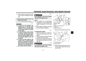
Fuel tank cap To open the fuel tank cap
Open the fuel tank cap lock cover, in-
sert the key into the lock, and then turn
it 1/4 turn clockwise. The lock will be re-
leased and the fuel tank cap can be
opened.
To close the fuel tank cap
1. Push the fuel tank cap into position
with the key inserted in the lock.
2. Turn the key counterclockwise to
the original position, remove it, and
then close the lock cover.
NOTE:The fuel tank cap cannot be closed un-
less the key is in the lock. In addition,
the key cannot be removed if the cap isnot properly closed and locked.
WARNING
EWA11090
Make sure that the fuel tank cap isproperly closed before riding.
1. Fuel tank cap lock cover
2. Unlock.
U5S5E1E0.book Page 16 Friday, June 22, 2007 1:03 PM
Page 31 of 98

INSTRUMENT AND CONTROL FUNCTIONS
3-17
3
EAU13220
Fuel Make sure that there is sufficient fuel in
the tank. When refueling, be sure to in-
sert the pump nozzle into the fuel tank
filler hole and to fill the tank to the bot-
tom of the filler tube as shown.
WARNING
EWA10880
�
Do not overfill the fuel tank, oth-
erwise it may overflow when the
fuel warms up and expands.
�
Avoid spilling fuel on the hot en-gine.
CAUTION:
ECA10070
Immediately wipe off spilled fuel
with a clean, dry, soft cloth, since
fuel may deteriorate painted surfac-es or plastic parts.
EAU13320
CAUTION:
ECA11400
Use only unleaded gasoline. The use
of leaded gasoline will cause severe
damage to internal engine parts,
such as the valves and piston rings,as well as to the exhaust system.
Your Yamaha engine has been de-
signed to use regular unleaded gaso-
line with a research octane number of
91 or higher. If knocking (or pinging) oc-
curs, use a gasoline of a different brandor premium unleaded fuel. Use of un-
leaded fuel will extend spark plug life
and reduce maintenance costs.
1. Fuel tank filler tube
2. Fuel level
Recommended fuel:
REGULAR UNLEADED GASOLINE
ONLY
Fuel tank capacity:
19.4 L (5.13 US gal) (4.27 Imp.gal)
Fuel reserve amount:
3.6 L (0.95 US gal) (0.79 Imp.gal)
U5S5E1E0.book Page 17 Friday, June 22, 2007 1:03 PM
Page 32 of 98

INSTRUMENT AND CONTROL FUNCTIONS
3-18
3
EAU13412
Fuel tank breather hose Before operating the motorcycle:�
Check the fuel tank breather hose
connection.
�
Check the fuel tank breather hose
for cracks or damage, and replace
it if damaged.
�
Make sure that the fuel tank
breather hose is not blocked, and
clean it if necessary.
EAU13442
Catalytic converters This vehicle is equipped with catalytic
converters in the exhaust system.
WARNING
EWA10860
The exhaust system is hot after op-
eration. Make sure that the exhaust
system has cooled down before do-ing any maintenance work.CAUTION:
ECA10700
The following precautions must be
observed to prevent a fire hazard or
other damages.�
Use only unleaded gasoline.
The use of leaded gasoline will
cause unrepairable damage to
the catalytic converter.
�
Never park the vehicle near pos-
sible fire hazards such as grass
or other materials that easily
burn.
�
Do not allow the engine to idletoo long.
EAU32980
Seat To remove the seat
1. Insert the key into the seat lock,
and then turn it counterclockwise.
2. While holding the key in that posi-
tion, lift the rear of the seat up, and
then pull the seat off.
To install the seat
1. Insert the projection on the front of
the seat into the seat holder as
shown.
1. Fuel tank breather hose
2. Original position (paint mark)
1. Seat lock
2. Unlock.
U5S5E1E0.book Page 18 Friday, June 22, 2007 1:03 PM