Page 17 of 98

INSTRUMENT AND CONTROL FUNCTIONS
3-3
3 To lock the steering
1. Turn the handlebars all the way to
the left.
2. Push the key in from the “OFF” po-
sition, and then turn it to “LOCK”
while still pushing it.
3. Remove the key.To unlock the steering
Push the key in, and then turn it to
“OFF” while still pushing it.
WARNING
EWA10060
Never turn the key to “OFF” or
“LOCK” while the vehicle is moving,
otherwise the electrical systems will
be switched off, which may result in
loss of control or an accident. Make
sure that the vehicle is stopped be-
fore turning the key to “OFF” or“LOCK”.
EAU34341
(Parking)
The steering is locked, and the taillight,
license plate light and auxiliary light are
on. The hazard lights and turn signal
lights can be turned on, but all other
electrical systems are off. The key can
be removed.
The steering must be locked before the
key can be turned to“”.
CAUTION:
ECA11020
Do not use the parking position for
an extended length of time, other-wise the battery may discharge.
1. Push.
2. Turn.
1. Push.
2. Turn.
U5S5E1E0.book Page 3 Friday, June 22, 2007 1:03 PM
Page 18 of 98

INSTRUMENT AND CONTROL FUNCTIONS
3-4
3
EAU11003
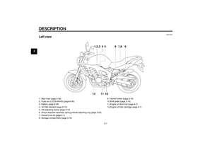
Indicator and warning lights
EAU11030
Turn signal indicator lights“”
and“”
The corresponding indicator light flash-
es when the turn signal switch is
pushed to the left or right.
EAU11060
Neutral indicator light“”
This indicator light comes on when the
transmission is in the neutral position.
EAU11080
High beam indicator light“”
This indicator light comes on when the
high beam of the headlight is switched
on.
EAU11250
Oil level warning light“”
This warning light comes on when the
engine oil level is low.
The electrical circuit of the warning light
can be checked by turning the key to
“ON”.
If the warning light does not come on
for a few seconds, then go off, have a
Yamaha dealer check the electrical cir-
cuit.NOTE:�
Even if the oil level is sufficient, the
warning light may flicker when
riding on a slope or during sudden
acceleration or deceleration, but
this is not a malfunction.
�
This model is also equipped with a
self-diagnosis device for the oil
level detection circuit. If the oil lev-
el detection circuit is defective, the
following cycle will be repeated un-
til the malfunction is corrected: The
oil level warning light will flash ten
times, then go off for 2.5 seconds.
If this occurs, have a Yamahadealer check the vehicle.
EAU11423
Coolant temperature warning
light“”
This warning light comes on when the
engine overheats. When this occurs,
stop the engine immediately and allow
the engine to cool.
The electrical circuit of the warning light
can be checked by turning the key to
“ON”.
If the warning light does not come on
for a few seconds, then go off, have a
Yamaha dealer check the electrical cir-
cuit.
1. Left turn signal indicator light“”
2. Right turn signal indicator light“”
3. Neutral indicator light“”
4. High beam indicator light“”
5. Engine trouble warning light“”
6. Oil level warning light“”
7. Coolant temperature warning light“”
8. Anti-lock Brake System (ABS) warning
light“” (for ABS models)
9. Immobilizer system indicator light
ABS
U5S5E1E0.book Page 4 Friday, June 22, 2007 1:03 PM
Page 19 of 98
INSTRUMENT AND CONTROL FUNCTIONS
3-5
3
CAUTION:
ECA10020
Do not operate the engine if it isoverheated.
U5S5E1E0.book Page 5 Friday, June 22, 2007 1:03 PM
Page 20 of 98
INSTRUMENT AND CONTROL FUNCTIONS
3-6
3
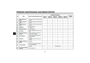
Coolant
temperatureDisplay Conditions What to do
Under 39 °C
(Under 103 °F)Message “Lo” is displayed. OK. Go ahead with riding.
40–116 °C
(104–242 °F)Temperature is displayed. OK. Go ahead with riding.
117–139 °C
(243–283 °F)Temperature display flashes.
Warning light comes on.Stop the vehicle and allow it to idle until
the coolant temperature goes down.
If the temperature does not go down,
stop the engine. (See page 6-40.)
Above 140 °C
(Above 284 °F)Message “HI” flashes.
Warning light comes on.Stop the engine and allow it to cool.
(See page 6-40.)
U5S5E1E0.book Page 6 Friday, June 22, 2007 1:03 PM
Page 21 of 98

INSTRUMENT AND CONTROL FUNCTIONS
3-7
3
EAU11530
Engine trouble warning light“”
This warning light comes on or flashes
when an electrical circuit monitoring the
engine is defective. When this occurs,
have a Yamaha dealer check the self-
diagnosis system. (See page 3-8 for an
explanation of the self-diagnosis de-
vice.)
The electrical circuit of the warning light
can be checked by turning the key to
“ON”. If the warning light does not come
on for a few seconds, then go off, have
a Yamaha dealer check the electrical
circuit.
EAU11543
ABS warning light“” (for ABS
models)
If this warning light comes on or flashes
while riding, the ABS may be defective.
If this occurs, have a Yamaha dealer
check the system as soon as possible.
(See page 3-15.)
WARNING
EWA10081
If the ABS warning light comes on or
flashes while riding, the brake sys-
tem reverts to conventional braking.
Therefore, be careful not to causethe wheels to lock during emergen-
cy braking. If the warning light
comes on or flashes while riding,
have a Yamaha dealer check the
brake system as soon as possible.
The electrical circuit of the warning light
can be checked by turning the key to
“ON”.
If the warning light does not come on or
remains on, have a Yamaha dealer
check the electrical circuit.
EAU38620
Immobilizer system indicator light
The electrical circuit of the indicator
light can be checked by turning the key
to “ON”.
If the indicator light does not come on
for a few seconds, then go off, have a
Yamaha dealer check the electrical cir-
cuit.
When the key is turned to “OFF” and 30
seconds have passed, the indicator
light will start flashing indicating the im-
mobilizer system is enabled. After 24
hours have passed, the indicator light
will stop flashing, however the immobi-
lizer system is still enabled.This model is also equipped with a self-
diagnosis device for the immobilizer
system. (See page 3-8 for an explana-
tion of the self-diagnosis device.)
ABS
U5S5E1E0.book Page 7 Friday, June 22, 2007 1:03 PM
Page 22 of 98

INSTRUMENT AND CONTROL FUNCTIONS
3-8
3
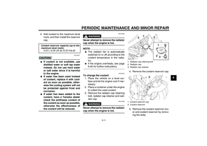
EAU39426
Multi-function meter unit
WARNING
EWA12421
Be sure to stop the vehicle before
making any setting changes to themulti-function meter unit.
The multi-function meter unit is
equipped with the following:�
a speedometer (which shows the
riding speed)
�
a tachometer (which shows engine
speed)
�
an odometer (which shows the to-
tal distance traveled)
�
two tripmeters (which show the
distance traveled since they were
last set to zero)
�
a fuel reserve tripmeter (which
shows the distance traveled since
the left segment of the fuel meter
started flashing)
�
a clock
�
a fuel meter
�
a coolant temperature display
�
an air intake temperature display
�
a self-diagnosis device
�
an LCD and tachometer bright-
ness control mode
NOTE:�
Be sure to turn the key to “ON” be-
fore using the “SELECT” and “RE-
SET” buttons.
�
For the U.K. only: To switch the
speedometer and odometer/trip-
meter displays between kilometers
and miles, press the “SELECT”button for at least one second.Tachometer
The electric tachometer allows the rider
to monitor the engine speed and keep it
within the ideal power range.
When the key is turned to “ON”, the ta-
chometer needle will sweep once
across the r/min range and then return
to zero r/min in order to test the electri-
cal circuit.
CAUTION:
ECA10031
Do not operate the engine in the ta-
chometer red zone.Red zone: 14000 r/min and above
1. Coolant temperature display/air intake tem-
perature display
2. Speedometer
3. Tachometer
4. Odometer/tripmeter/fuel reserve tripmeter
5.“SELECT” button
6.“RESET” button
7. Clock
8. Fuel meter
1. Tachometer
2. Tachometer red zone
U5S5E1E0.book Page 8 Friday, June 22, 2007 1:03 PM
Page 23 of 98

INSTRUMENT AND CONTROL FUNCTIONS
3-9
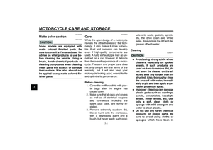
3 Clock
The clock displays when the key is
turned to “ON”. In addition, the clock
can be displayed for 10 seconds by
pushing the “SELECT” button when the
main switch is in the “OFF”, “LOCK”
or“” position.
To set the clock
1. Turn the key to “ON”.
2. Push the “SELECT” button and
“RESET” button together for at
least two seconds.
3. When the hour digits start flashing,
push the “RESET” button to set the
hours.4. Push the “SELECT” button, and
the minute digits will start flashing.
5. Push the “RESET” button to set
the minutes.
6. Push the “SELECT” button and
then release it to start the clock.
Odometer and tripmeter modes
Push the “SELECT” button to switch
the display between the odometer
mode “ODO” and the tripmeter modes
“TRIP A” and “TRIP B” in the following
order:
TRIP A → TRIP B → ODO → TRIP A
When the fuel amount in the fuel tank
decreases to 3.6 L (0.95 US gal) (0.79
Imp.gal), the left segment of the fuel
meter will start flashing, and the odom-eter display will automatically change to
the fuel reserve tripmeter mode “F-
TRIP” and start counting the distance
traveled from that point. In that case,
push the “SELECT” button to switch the
display between the various tripmeter
and odometer modes in the following
order:
F-TRIP → TRIP A → TRIP B → ODO
→ F-TRIP
To reset a tripmeter, select it by push-
ing the “SELECT” button, and then
push the “RESET” button for at least
one second. If you do not reset the fuel
reserve tripmeter manually, it will reset
itself automatically and the display will
return to the prior mode after refueling
and traveling 5 km (3 mi).1. Clock
2. Speedometer
1. Odometer/tripmeter/fuel reserve tripmeter
U5S5E1E0.book Page 9 Friday, June 22, 2007 1:03 PM
Page 24 of 98
 as the fuel")
INSTRUMENT AND CONTROL FUNCTIONS
3-10
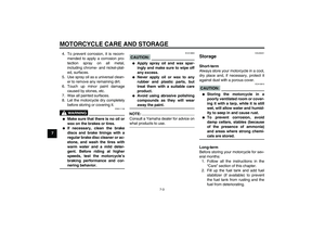
3Fuel meter
The fuel meter indicates the amount of
fuel in the fuel tank. The display seg-
ments of the fuel meter disappear to-
wards “E” (Empty) as the fuel level
decreases. When the last segment on
the left starts flashing, refuel as soon as
possible.
NOTE:This fuel meter is equipped with a self-
diagnosis system. If the electrical circuit
is defective, the following cycle will be
repeated until the malfunction is cor-
rected: “E” (Empty), “F” (Full) and
symbol“” will flash eight times, thengo off for approximately 3 seconds. If
this occurs, have a Yamaha dealer
check the electrical circuit.
Coolant temperature mode
The coolant temperature display indi-
cates the temperature of the coolant.
Push the “RESET” button to switch the
coolant temperature display to the air
intake temperature display.NOTE:When the coolant temperature display
is selected, “C” is displayed for one
second, and then the coolant tempera-ture is displayed.
CAUTION:
ECA10020
Do not operate the engine if it isoverheated.
Air intake temperature mode
The air intake temperature display indi-
cates the temperature of the air drawn
into the air filter case. Push the “RE-
SET” button to switch the coolant tem-
perature display to the air intake
temperature display.NOTE:�
Even if the air intake temperature
is set to be displayed, the coolant
temperature warning light comes
on when the engine overheats.
1. Fuel meter
1. Coolant temperature display
1. Air intake temperature display
U5S5E1E0.book Page 10 Friday, June 22, 2007 1:03 PM


Message “Lo” is displayed. OK. Go ahead with riding.
40–116 °C
(104–242")