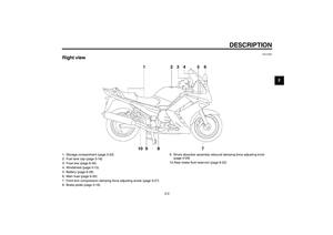
Page 65 of 102

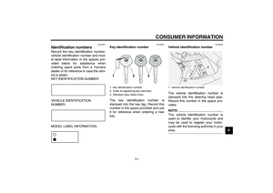
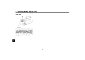
PERIODIC MAINTENANCE AND MINOR REPAIR
6-11
6
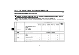
NOTE:
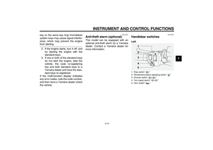
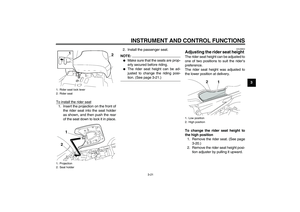
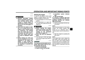
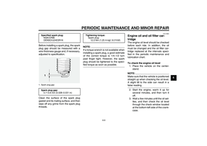
Make sure that the O-ring is properlyseated.
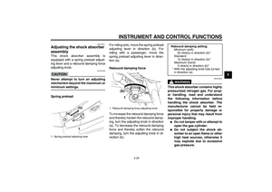
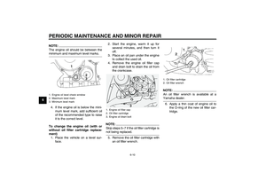
7. Install the new oil filter cartridge,
and then tighten it to the specified
torque with a torque wrench.8. Install the engine oil drain bolt, and
then tighten it to the specified
torque.
NOTE:
Check the washer for damage and re-place it if necessary.
9. Refill with the specified amount of
the recommended engine oil, and
then install and tighten the oil filler
cap.
NOTE:Be sure to wipe off spilled oil on any
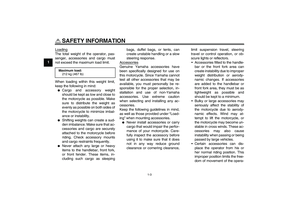
parts after the engine and exhaust sys-tem have cooled down.CAUTION:
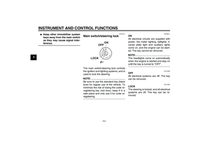
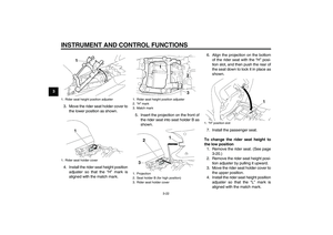
ECA11620
�
In order to prevent clutch slip-
page (since the engine oil also
lubricates the clutch), do not
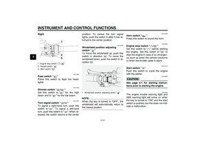
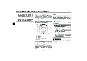
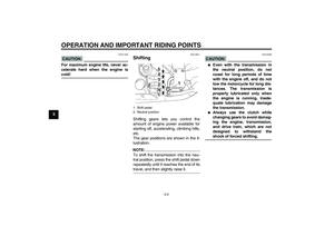
mix any chemical additives. Do
not use oils with a diesel speci-
fication of “CD” or oils of a high-
er quality than specified. In
addition, do not use oils labeled
“ENERGY CONSERVING II” or
higher.
�
Make sure that no foreign mate-rial enters the crankcase.
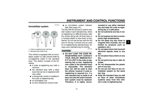
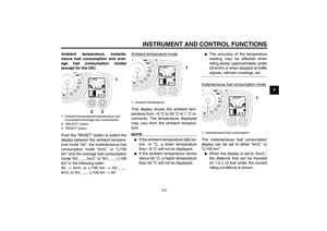
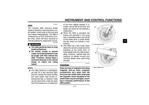
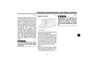
1. O-ring
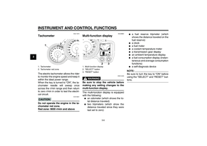
1. Oil filter cartridge
2. Torque wrench
Tightening torque:
Oil filter cartridge:
17 Nm (1.7 m·kgf, 12 ft·lbf)
Tightening torque:
Engine oil drain bolt:
43 Nm (4.3 m·kgf, 31 ft·lbf)
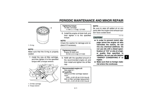
Recommended engine oil:
See page 8-1.
Oil quantity:
Without oil filter cartridge replace-
ment:
3.80 L (4.02 US qt) (3.34 Imp.qt)
With oil filter cartridge replacement:
4.00 L (4.23 US qt) (3.52 Imp.qt)
U3P6E2E0.book Page 11 Friday, September 14, 2007 9:43 AM
Page 66 of 102

PERIODIC MAINTENANCE AND MINOR REPAIR
6-12
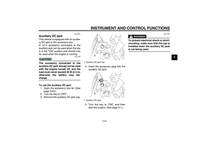
610. Start the engine, and then let it idle
for several minutes while checking
it for oil leakage. If oil is leaking, im-
mediately turn the engine off and
check for the cause.
NOTE:After the engine is started, the engine
oil level warning light should go off if theoil level is sufficient.CAUTION:
ECA10400
If the oil level warning light flickers
or remains on, immediately turn the
engine off and have a Yamaha dealercheck the vehicle.11. Turn the engine off, and then
check the oil level and correct it if
necessary.
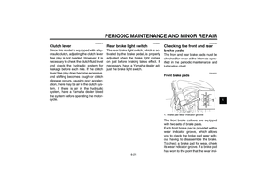
EAU20014
Final gear oil The final gear case must be checked
for oil leakage before each ride. If any
leakage is found, have a Yamaha deal-
er check and repair the vehicle. In addi-
tion, the final gear oil must be changed
as follows at the intervals specified in
the periodic maintenance and lubrica-
tion chart.
WARNING
EWA10370
�
Make sure that no foreign mate-
rial enters the final gear case.
�
Make sure that no oil gets on thetire or wheel.
To check the final gear oil level
1. Place the vehicle on the center-
stand.
NOTE:�
The final gear oil level must be
checked on a cold engine.
�
Make sure that the vehicle is posi-
tioned straight up when checking
the oil level. A slight tilt to the sidecan result in a false reading.
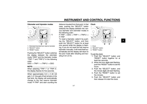
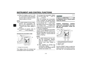
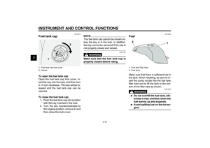
1.“CD” specification
2.“ENERGY CONSERVING II”
1
2
U3P6E2E0.book Page 12 Friday, September 14, 2007 9:43 AM
Page 67 of 102

PERIODIC MAINTENANCE AND MINOR REPAIR
6-13
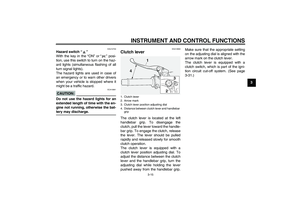
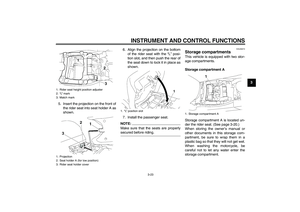
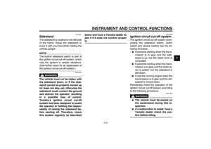
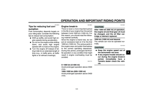
6 2. Remove the final gear oil filler bolt,
and then check the oil level in the
final gear case.
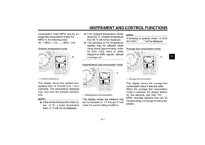
NOTE:The oil level should be at the brim of thefiller hole.
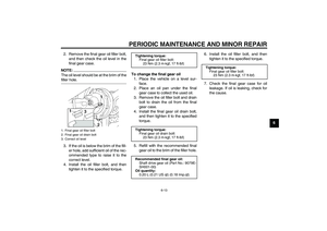
3. If the oil is below the brim of the fill-
er hole, add sufficient oil of the rec-
ommended type to raise it to the
correct level.
4. Install the oil filler bolt, and then
tighten it to the specified torque.To change the final gear oil
1. Place the vehicle on a level sur-
face.
2. Place an oil pan under the final
gear case to collect the used oil.
3. Remove the oil filler bolt and drain
bolt to drain the oil from the final
gear case.
4. Install the final gear oil drain bolt,
and then tighten it to the specified
torque.
5. Refill with the recommended final
gear oil to the brim of the filler hole.6. Install the oil filler bolt, and then
tighten it to the specified torque.
7. Check the final gear case for oil
leakage. If oil is leaking, check for
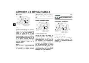
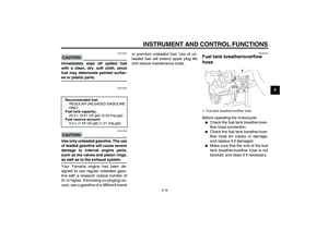
the cause.1. Final gear oil filler bolt
2. Final gear oil drain bolt
3. Correct oil level
Tightening torque:
Final gear oil filler bolt:
23 Nm (2.3 m·kgf, 17 ft·lbf)
Tightening torque:
Final gear oil drain bolt:
23 Nm (2.3 m·kgf, 17 ft·lbf)
Recommended final gear oil:
Shaft drive gear oil (Part No.: 9079E-
SH001-00)
Oil quantity:
0.20 L (0.21 US qt) (0.18 Imp.qt)
Tightening torque:
Final gear oil filler bolt:
23 Nm (2.3 m·kgf, 17 ft·lbf)
U3P6E2E0.book Page 13 Friday, September 14, 2007 9:43 AM
Page 68 of 102

PERIODIC MAINTENANCE AND MINOR REPAIR
6-14
6
EAU20070
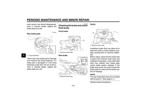
Coolant The coolant level should be checked
before each ride. In addition, the cool-
ant must be changed at the intervals
specified in the periodic maintenance
and lubrication chart.
EAU39512
To check the coolant level
The coolant level should be checked as
follows before each ride. In addition,
the coolant must be changed at the in-
tervals specified in the periodic mainte-
nance and lubrication chart.
1. Place the vehicle on the center-
stand.NOTE:�
The coolant level must be checked
on a cold engine since the level
varies with engine temperature.
�
Make sure that the vehicle is posi-
tioned straight up when checking
the coolant level. A slight tilt to theside can result in a false reading.
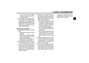
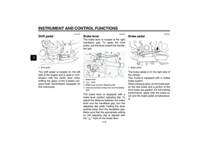
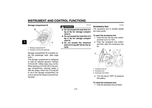
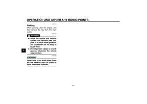
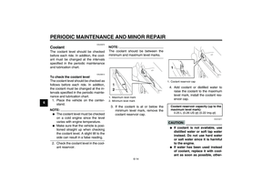
2. Check the coolant level in the cool-
ant reservoir.
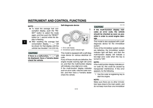
NOTE:The coolant should be between theminimum and maximum level marks.
3. If the coolant is at or below the
minimum level mark, remove the
coolant reservoir cap.4. Add coolant or distilled water to
raise the coolant to the maximum
level mark, install the coolant res-
ervoir cap.
CAUTION:
ECA10471
�
If coolant is not available, use
distilled water or soft tap water
instead. Do not use hard water
or salt water since it is harmful
to the engine.
�
If water has been used instead
of coolant, replace it with cool-
ant as soon as possible, other-
1. Maximum level mark
2. Minimum level mark
1. Coolant reservoir capCoolant reservoir capacity (up to the
maximum level mark):
0.25 L (0.26 US qt) (0.22 Imp.qt)
U3P6E2E0.book Page 14 Friday, September 14, 2007 9:43 AM
Page 69 of 102

PERIODIC MAINTENANCE AND MINOR REPAIR
6-15
6 wise the cooling system will not
be protected against frost and
corrosion.
�
If water has been added to the
coolant, have a Yamaha dealer
check the antifreeze content of
the coolant as soon as possible,
otherwise the effectiveness ofthe coolant will be reduced.WARNING
EWA10380
Never attempt to remove the radiatorcap when the engine is hot.NOTE:�
The radiator fans are automatically
switched on or off according to the
coolant temperature in the radia-
tor.
�
If the engine overheats, see page6-34 for further instructions.
EAU33030
Changing the coolant
WARNING
EWA10380
Never attempt to remove the radiatorcap when the engine is hot.The coolant must be changed at the in-
tervals specified in the periodic mainte-
nance and lubrication chart. Have a
Yamaha dealer change the coolant.
EAU20471
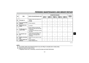
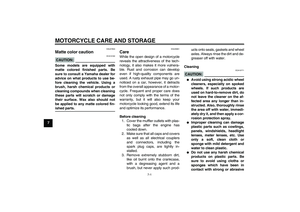
Cleaning the air filter element The air filter element should be cleaned
at the intervals specified in the periodic
maintenance and lubrication chart.
Clean the air filter element more fre-
quently if you are riding in unusually
wet or dusty areas.
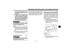
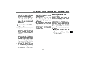
1. Remove panel B. (See page 6-7.)
2. Remove the intake air shroud by
removing the screw and the quick
fastener screws.
3. Remove the air filter case cover by
removing the screws.1. Intake air shroud
2. Screw
3. Quick fastener screw
U3P6E2E0.book Page 15 Friday, September 14, 2007 9:43 AM
Page 70 of 102

PERIODIC MAINTENANCE AND MINOR REPAIR
6-16
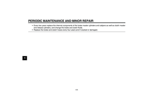
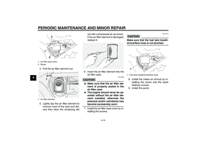
64. Pull the air filter element out.
5. Lightly tap the air filter element to
remove most of the dust and dirt,
and then blow the remaining dirtout with compressed air as shown.
If the air filter element is damaged,
replace it.
6. Insert the air filter element into the
air filter case.
CAUTION:
ECA10480
�
Make sure that the air filter ele-
ment is properly seated in the
air filter case.
�
The engine should never be op-
erated without the air filter ele-
ment installed, otherwise the
piston(s) and/or cylinder(s) maybecome excessively worn.
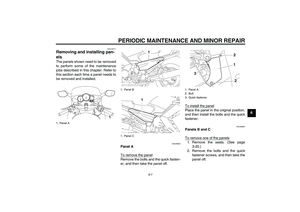
7. Install the air filter case cover by in-
stalling the screws.
CAUTION:
ECA15410
Make sure that the fuel tank breath-er/overflow hose is not pinched.
8. Install the intake air shroud by in-
stalling the screw and the quick
fastener screws.
9. Install the panel.
1. Air filter case cover
2. Screw
1. Air filter element
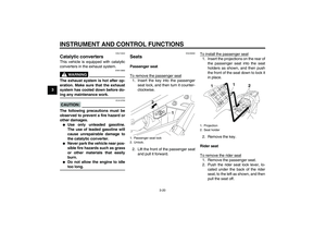
1. Fuel tank breather/overflow hose
U3P6E2E0.book Page 16 Friday, September 14, 2007 9:43 AM
Page 71 of 102

PERIODIC MAINTENANCE AND MINOR REPAIR
6-17
6
EAU44730
Checking the engine idling
speed The engine idling speed must be
checked as follows and, if necessary,
adjusted by a Yamaha dealer at the in-
tervals specified in the periodic mainte-
nance and lubrication chart.
Start the engine and warm it up for sev-
eral minutes at 1000–2000 r/min while
occasionally revving it to 4000–5000
r/min.
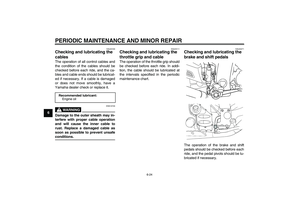
EAU21382
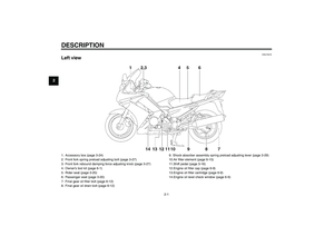
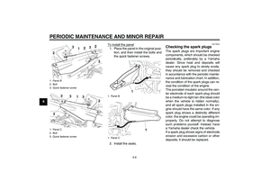
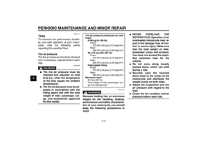
Checking the throttle cable
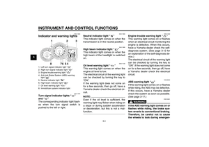
free play The throttle cable free play should mea-
sure 3.0–5.0 mm (0.12–0.20 in) at the
throttle grip. Periodically check the
throttle cable free play and, if neces-
sary, have a Yamaha dealer adjust it.
EAU21401
Valve clearance The valve clearance changes with use,
resulting in improper air-fuel mixture
and/or engine noise. To prevent this
from occurring, the valve clearance
must be adjusted by a Yamaha dealer
at the intervals specified in the periodic
maintenance and lubrication chart.
Engine idling speed:
1000–1100 r/min
1. Throttle cable free play
U3P6E2E0.book Page 17 Friday, September 14, 2007 9:43 AM
Page 72 of 102

PERIODIC MAINTENANCE AND MINOR REPAIR
6-18
6
EAU21771
Tires To maximize the performance, durabil-
ity, and safe operation of your motor-
cycle, note the following points
regarding the specified tires.
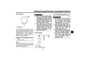
Tire air pressure
The tire air pressure should be checked
and, if necessary, adjusted before each
ride.
WARNING
EWA10500
�
The tire air pressure must be
checked and adjusted on cold
tires (i.e., when the temperature
of the tires equals the ambient
temperature).
�
The tire air pressure must be ad-
justed in accordance with the
riding speed and with the total
weight of rider, passenger, car-
go, and accessories approvedfor this model.
WARNING
EWA11020
Because loading has an enormous
impact on the handling, braking,
performance and safety characteris-
tics of your motorcycle, you should
keep the following precautions in
mind.
�
NEVER OVERLOAD THE
MOTORCYCLE! Operation of an
overloaded motorcycle may re-
sult in tire damage, loss of con-
trol, or severe injury. Make sure
that the total weight of rider,
passenger, cargo, and accesso-
ries does not exceed the speci-
fied maximum load for the
vehicle.
�
Do not carry along loosely
packed items, which can shift
during a ride.
�
Securely pack the heaviest
items close to the center of the
motorcycle and distribute the
weight evenly on both sides.
�
Adjust the suspension and tire
air pressure with regard to the
load.
�
Check the tire condition and airpressure before each ride.
Tire air pressure (measured on cold
tires):
0–90 kg (0–198 lb):
Front:
270 kPa (39 psi) (2.70 kgf/cm²)
Rear:
290 kPa (42 psi) (2.90 kgf/cm²)
90–212 kg (198–467 lb):
Front:
270 kPa (39 psi) (2.70 kgf/cm²)
Rear:
290 kPa (42 psi) (2.90 kgf/cm²)
High-speed riding:
Front:
270 kPa (39 psi) (2.70 kgf/cm²)
Rear:
290 kPa (42 psi) (2.90 kgf/cm²)
Maximum load*:
212 kg (467 lb)
* Total weight of rider, passenger, car-
go and accessories
U3P6E2E0.book Page 18 Friday, September 14, 2007 9:43 AM