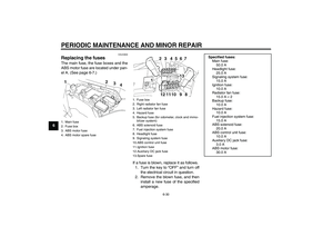
Page 33 of 102

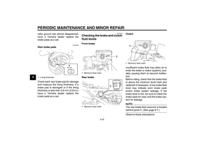
INSTRUMENT AND CONTROL FUNCTIONS
3-19
3
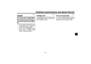
CAUTION:
ECA10070
Immediately wipe off spilled fuel
with a clean, dry, soft cloth, since
fuel may deteriorate painted surfac-es or plastic parts.
EAU13320
CAUTION:
ECA11400
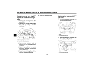
Use only unleaded gasoline. The use
of leaded gasoline will cause severe
damage to internal engine parts,
such as the valves and piston rings,as well as to the exhaust system.
Your Yamaha engine has been de-
signed to use regular unleaded gaso-
line with a research octane number of
91 or higher. If knocking (or pinging) oc-
curs, use a gasoline of a different brandor premium unleaded fuel. Use of un-
leaded fuel will extend spark plug life
and reduce maintenance costs.
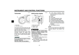
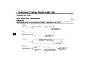
EAU39450
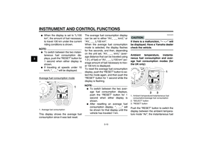
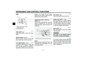
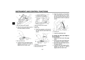
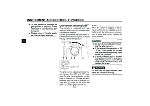
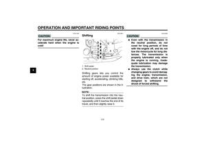
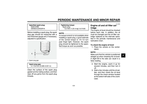
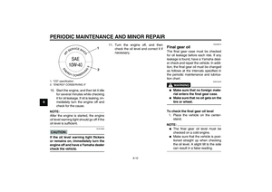
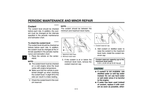
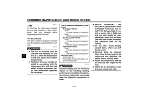
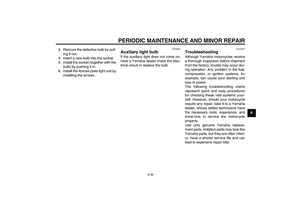
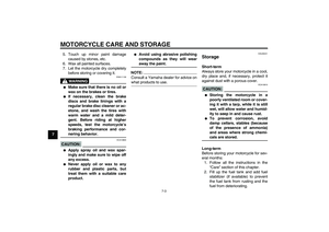
Fuel tank breather/overflow
hose Before operating the motorcycle:�
Check the fuel tank breather/over-
flow hose connection.
�
Check the fuel tank breather/over-
flow hose for cracks or damage,
and replace it if damaged.
�
Make sure that the end of the fuel
tank breather/overflow hose is not
blocked, and clean it if necessary.
Recommended fuel:
REGULAR UNLEADED GASOLINE
ONLY
Fuel tank capacity:
25.0 L (6.61 US gal) (5.50 Imp.gal)
Fuel reserve amount:
5.5 L (1.45 US gal) (1.21 Imp.gal)
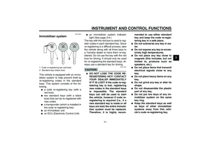
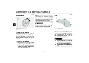
1. Fuel tank breather/overflow hose
U3P6E2E0.book Page 19 Friday, September 14, 2007 9:43 AM
Page 34 of 102

INSTRUMENT AND CONTROL FUNCTIONS
3-20
3
EAU13442
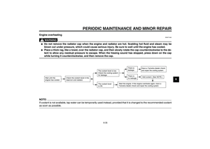
Catalytic converters This vehicle is equipped with catalytic
converters in the exhaust system.
WARNING
EWA10860
The exhaust system is hot after op-
eration. Make sure that the exhaust
system has cooled down before do-ing any maintenance work.CAUTION:
ECA10700
The following precautions must be
observed to prevent a fire hazard or
other damages.�
Use only unleaded gasoline.
The use of leaded gasoline will
cause unrepairable damage to
the catalytic converter.
�
Never park the vehicle near pos-
sible fire hazards such as grass
or other materials that easily
burn.
�
Do not allow the engine to idletoo long.
EAU39492
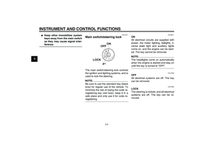
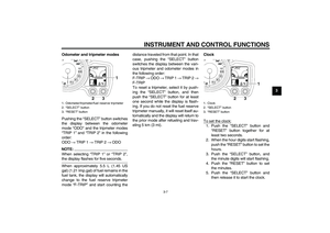
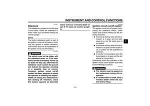
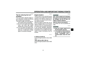
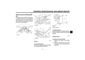
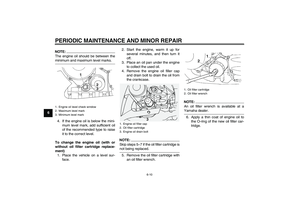
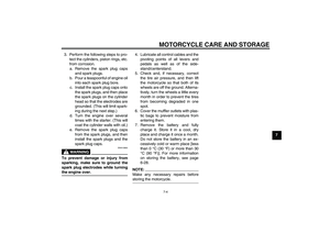
Seats Passenger seat
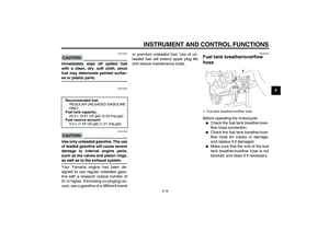
To remove the passenger seat1. Insert the key into the passenger
seat lock, and then turn it counter-
clockwise.
2. Lift the front of the passenger seat
and pull it forward.To install the passenger seat
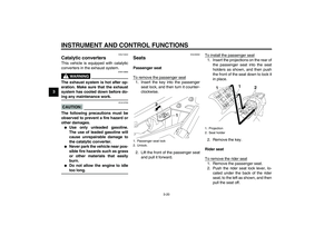
1. Insert the projections on the rear of
the passenger seat into the seat
holders as shown, and then push
the front of the seat down to lock it
in place.
2. Remove the key.
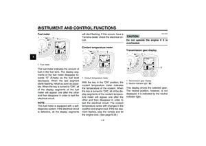
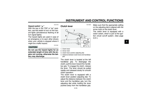
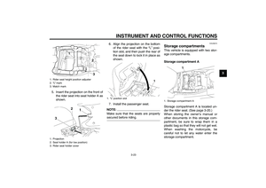
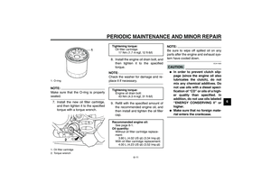
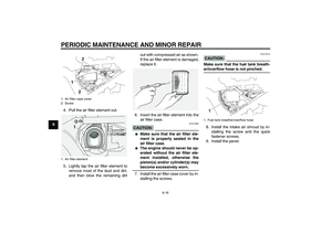
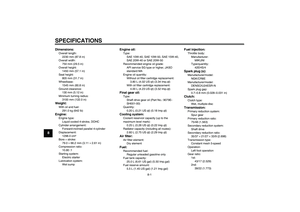
Rider seat
To remove the rider seat1. Remove the passenger seat.
2. Push the rider seat lock lever, lo-
cated under the back of the rider
seat, to the left as shown, and then
pull the seat off.
1. Passenger seat lock
2. Unlock.
1. Projection
2. Seat holder
U3P6E2E0.book Page 20 Friday, September 14, 2007 9:43 AM
Page 35 of 102
INSTRUMENT AND CONTROL FUNCTIONS
3-21
3
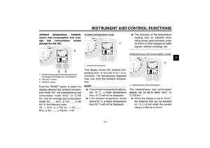
To install the rider seat
1. Insert the projection on the front of
the rider seat into the seat holder
as shown, and then push the rear
of the seat down to lock it in place.2. Install the passenger seat.
NOTE:�
Make sure that the seats are prop-
erly secured before riding.
�
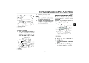
The rider seat height can be ad-
justed to change the riding posi-tion. (See page 3-21.)
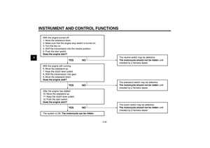
EAU39632
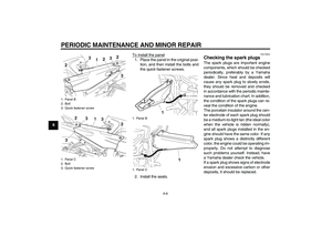
Adjusting the rider seat height The rider seat height can be adjusted to
one of two positions to suit the rider’s
preference.
The rider seat height was adjusted to
the lower position at delivery.
To change the rider seat height to
the high position
1. Remove the rider seat. (See page
3-20.)
2. Remove the rider seat height posi-
tion adjuster by pulling it upward.
1. Rider seat lock lever
2. Rider seat
1. Projection
2. Seat holder
1. Low position
2. High position
U3P6E2E0.book Page 21 Friday, September 14, 2007 9:43 AM
Page 36 of 102

INSTRUMENT AND CONTROL FUNCTIONS
3-22
3
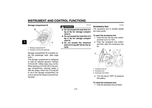
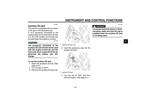
3. Move the rider seat holder cover to
the lower position as shown.
4. Install the rider seat height position
adjuster so that the “H” mark is
aligned with the match mark.5. Insert the projection on the front of
the rider seat into seat holder B as
shown.6. Align the projection on the bottom
of the rider seat with the “H” posi-
tion slot, and then push the rear of
the seat down to lock it in place as
shown.
7. Install the passenger seat.
To change the rider seat height to
the low position
1. Remove the rider seat. (See page
3-20.)
2. Remove the rider seat height posi-
tion adjuster by pulling it upward.
3. Move the rider seat holder cover to
the upper position.
4. Install the rider seat height position
adjuster so that the “L” mark is
aligned with the match mark.
1. Rider seat height position adjuster
1. Rider seat holder cover
1. Rider seat height position adjuster
2.“H” mark
3. Match mark
1. Projection
2. Seat holder B (for high position)
3. Rider seat holder cover
1.“H” position slot
U3P6E2E0.book Page 22 Friday, September 14, 2007 9:43 AM
Page 37 of 102

INSTRUMENT AND CONTROL FUNCTIONS
3-23
3
5. Insert the projection on the front of
the rider seat into seat holder A as
shown.6. Align the projection on the bottom
of the rider seat with the “L” posi-
tion slot, and then push the rear of
the seat down to lock it in place as
shown.
7. Install the passenger seat.
NOTE:
Make sure that the seats are properlysecured before riding.
EAU39472
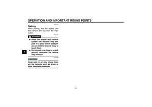
Storage compartments This vehicle is equipped with two stor-
age compartments.
Storage compartment A
Storage compartment A is located un-
der the rider seat. (See page 3-20.)
When storing the owner’s manual or
other documents in this storage com-
partment, be sure to wrap them in a
plastic bag so that they will not get wet.
When washing the motorcycle, be
careful not to let any water enter the
storage compartment.
1. Rider seat height position adjuster
2.“L” mark
3. Match mark
1. Projection
2. Seat holder A (for low position)
3. Rider seat holder cover
1.“L” position slot
1. Storage compartment A
U3P6E2E0.book Page 23 Friday, September 14, 2007 9:43 AM
Page 38 of 102

This storage compartment is designed
to hold an optional genu")
INSTRUMENT AND CONTROL FUNCTIONS
3-24
3Storage compartment B
Storage compartment B is located un-
der the passenger seat. (See page
3-20.)
This storage compartment is designed
to hold an optional genuine Yamaha
CYCLELOK. (Other locks may not fit.)
When placing a CYCLELOK in the stor-
age compartment, securely fasten it
with the straps. When the CYCLELOK
is not in the storage compartment, be
sure to secure the straps to prevent los-
ing them.
WARNING
EWA14420
�
Do not exceed the load limit of 1
kg (2 lb) for storage compart-
ment A.
�
Do not exceed the load limit of 3
kg (7 lb) for storage compart-
ment B.
�
Do not exceed the maximum
load of 212 kg (467 lb) for the ve-hicle.
EAU39480
Accessory box The accessory box is located beside
the meter panel.
To open the accessory box
1. Insert the key into the main switch,
and then turn it to “ON”.
2. Push the accessory box button,
and then open the accessory box
lid.
3. Turn the key to “OFF” to preserve
the battery.
To close the accessory box
1. Fold the accessory box lid down.
1. Storage compartment B
2. Yamaha CYCLELOK (optional)
1. Accessory box lid
2. Accessory box
3. Accessory box button
U3P6E2E0.book Page 24 Friday, September 14, 2007 9:43 AM
Page 39 of 102

INSTRUMENT AND CONTROL FUNCTIONS
3-25
3 2. Remove the key.
CAUTION:
ECA11800
Do not place heat-sensitive items in
the accessory box. The accessory
box gets extremely hot especiallywhen the engine is running or is hot.
WARNING
EWA11421
�
Do not exceed the load limit of
0.3 kg (0.66 lb) for the accessory
box.
�
Do not exceed the maximum
load of 212 kg (467 lb) for the ve-hicle.
EAU39611
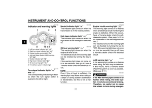
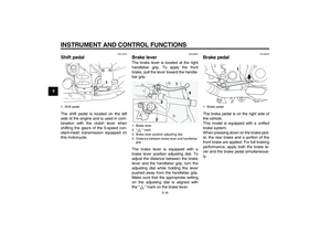
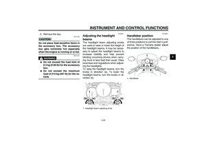
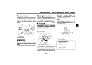
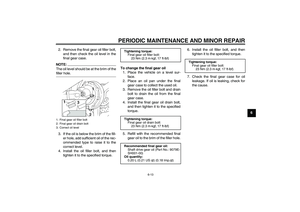
Adjusting the headlight
beams The headlight beam adjusting knobs
are used to raise or lower the height of
the headlight beams. It may be neces-
sary to adjust the headlight beams to
increase visibility and help prevent
blinding oncoming drivers when carry-
ing more or less load than usual. Obey
local laws and regulations when adjust-
ing the headlights.
To raise the headlight beams, turn the
knobs in direction (a). To lower the
headlight beams, turn the knobs in di-
rection (b).
EAU39641
Handlebar position The handlebars can be adjusted to one
of three positions to suit the rider’s pref-
erence. Have a Yamaha dealer adjust
the position of the handlebars.
1. Headlight beam adjusting knob
1. Handlebar
U3P6E2E0.book Page 25 Friday, September 14, 2007 9:43 AM
Page 40 of 102
INSTRUMENT AND CONTROL FUNCTIONS
3-26
3
EAU39621
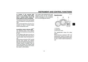
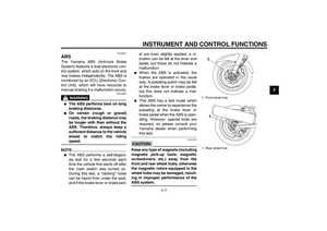
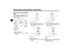
Opening and closing the cowl-
ings The cowlings can be tilted back 30 mm
(1.18 in) for added ventilation to suit the
riding conditions.
To open a cowling
1. Remove the quick fastener
screws.2. Pull the cowling to the open posi-
tion, and then install the quick fas-
tener screws.
To close a cowling
1. Remove the quick fastener
screws.2. Push the cowling to the closed po-
sition, and then install the quick
fastener screws.
NOTE:Make sure that the cowling is properlyinstalled before riding.
1. Closed position
2. Open position
3. Cowling
1. Quick fastener screw
1. Open position
1. Quick fastener screw
1. Closed position
U3P6E2E0.book Page 26 Friday, September 14, 2007 9:43 AM


 for added ventilation to suit the
riding conditions.
To open a cowli")