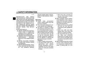
Page 25 of 102

INSTRUMENT AND CONTROL FUNCTIONS
3-11
3 consumption mode “MPG” and the av-
erage fuel consumption mode “AV_ _._
MPG” in the following order:
Air → MPG → AV_ _._ MPG → Air
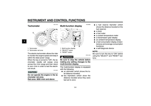
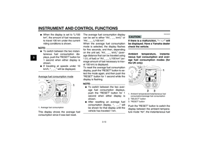
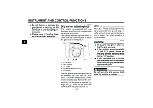
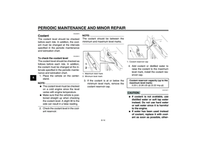
Ambient temperature mode
This display shows the ambient tem-
perature from –9 °C to 50 °C in 1 °C in-
crements. The temperature displayed
may vary from the ambient tempera-
ture.NOTE:�
If the ambient temperature falls be-
low –9 °C, a lower temperature
than –9 °C will not be displayed.
�
If the ambient temperature climbs
above 50 °C, a higher temperature
than 50 °C will not be displayed.
�
The accuracy of the temperature
reading may be affected when
riding slowly [approximately under
20 km/h (12.5 mi/h)] or when
stopped at traffic signals, railroadcrossings, etc.
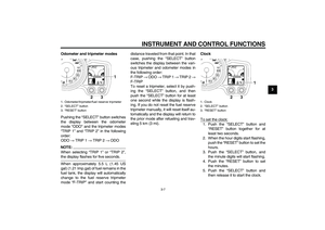
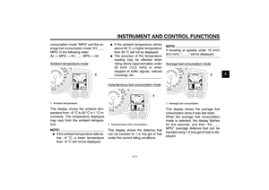
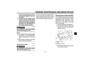
Instantaneous fuel consumption mode
This display shows the distance that
can be traveled on 1.0 Imp.gal of fuel
under the current riding conditions.
NOTE:If traveling at speeds under 10 km/h(6.0 mi/h), “_ _._” will be displayed.
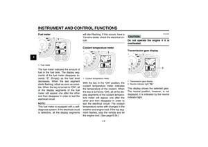
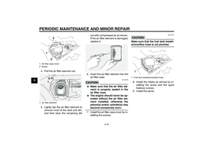
Average fuel consumption modeThis display shows the average fuel
consumption since it was last reset.
When the average fuel consumption
mode is selected, the display flashes
for five seconds, and then “AV_ _._
MPG” (average distance that can be
traveled using 1.0 Imp.gal of fuel) is dis-
played.
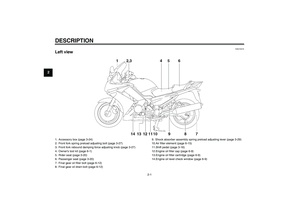
1. Ambient temperature
1. Instantaneous fuel consumption
1. Average fuel consumption
U3P6E2E0.book Page 11 Friday, September 14, 2007 9:43 AM
Page 26 of 102

INSTRUMENT AND CONTROL FUNCTIONS
3-12
3
NOTE:�
To reset the average fuel con-
sumption display, push the “RE-
SET” button to select the mode
again, and then push the “RESET”
button for 1 second while the dis-
play is flashing.
�
After resetting the average fuel
consumption display, “_ _._” will
be shown for that display until thevehicle has traveled 1 km (0.6 mi).
CAUTION:
ECA15472
If there is a malfunction, “– –.–” will
be displayed. Have a Yamaha dealercheck the vehicle.Self-diagnosis device
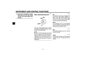
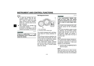
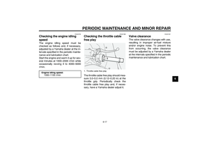
This model is equipped with a self-diag-
nosis device for various electrical cir-
cuits.
If any of those circuits are defective, the
engine trouble warning light will come
on, and then the multi-function display
will indicate a two-digit error code.
If the multi-function display indicates
such an error code, note the code num-
ber, and then have a Yamaha dealer
check the vehicle.
CAUTION:
ECA11790
If the multi-function display indi-
cates an error code, the vehicle
should be checked as soon as pos-
sible in order to avoid engine dam-age.
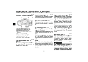
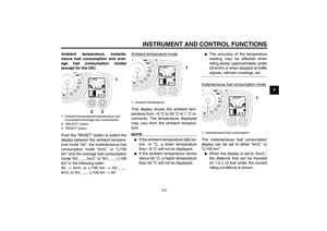
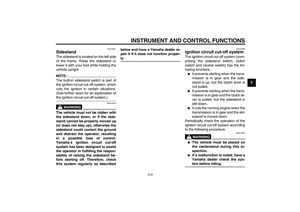
This model is also equipped with a self-
diagnosis device for the immobilizer
system.
If any of the immobilizer system circuits
are defective, the immobilizer system
indicator light will flash, and then the
multi-function display will indicate a
two-digit error code when the key is
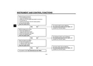
turned to “ON”.NOTE:If the multi-function display indicates er-
ror code 52, this could be caused by
transponder interference. If this errorappears, try the following.
1. Use the code re-registering key to
start the engine.NOTE:Make sure there are no other immobi-
lizer keys close to the main switch, and
do not keep more than one immobilizer
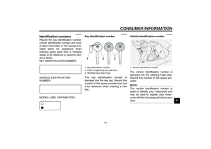
1. Error code display
2. Immobilizer system indicator light
U3P6E2E0.book Page 12 Friday, September 14, 2007 9:43 AM
Page 27 of 102
INSTRUMENT AND CONTROL FUNCTIONS
3-13
3 key on the same key ring! Immobilizer
system keys may cause signal interfer-
ence, which may prevent the engine
from starting.
2. If the engine starts, turn it off, and
try starting the engine with the
standard keys.
3. If one or both of the standard keys
do not start the engine, take the
vehicle, the code re-registering
key and both standard keys to a
Yamaha dealer and have the stan-
dard keys re-registered.
If the multi-function display indicates
any error codes, note the code number,
and then have a Yamaha dealer check
the vehicle.
EAU12331
Anti-theft alarm (optional) This model can be equipped with an
optional anti-theft alarm by a Yamaha
dealer. Contact a Yamaha dealer for
more information.
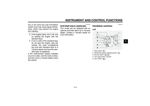
EAU12347
Handlebar switches Left1. Pass switch“”
2. Windshield position adjusting switch“”
3. Dimmer switch“/”
4. Turn signal switch“/”
5. Horn switch“”
U3P6E2E0.book Page 13 Friday, September 14, 2007 9:43 AM
Page 28 of 102

INSTRUMENT AND CONTROL FUNCTIONS
3-14
3Right
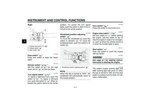
EAU12380
Pass switch“”
Press this switch to flash the head-
lights.
EAU12400
Dimmer switch“/”
Set this switch to“” for the high
beam and to“” for the low beam.
EAU12460
Turn signal switch“/”
To signal a right-hand turn, push this
switch to“”. To signal a left-hand
turn, push this switch to“”. When re-
leased, the switch returns to the centerposition. To cancel the turn signal
lights, push the switch in after it has re-
turned to the center position.
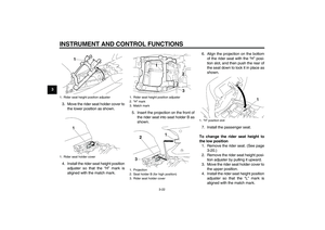
EAU12493
Windshield position adjusting
switch“”
To move the windshield up, push this
switch in direction (a). To move the
windshield down, push the switch in di-
rection (b).NOTE:When the key is turned to “OFF”, the
windshield will automatically return tothe lowest position.
EAU12500
Horn switch“”
Press this switch to sound the horn.
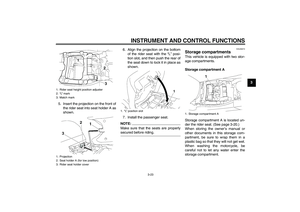
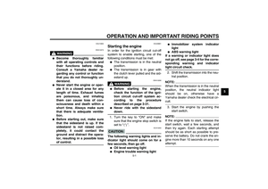
EAU12660
Engine stop switch“/”
Set this switch to“” before starting
the engine. Set this switch to“” to
stop the engine in case of an emergen-
cy, such as when the vehicle overturns
or when the throttle cable is stuck.
EAU12710
Start switch“”
Push this switch to crank the engine
with the starter.CAUTION:
ECA10050
See page 5-1 for starting instruc-tions prior to starting the engine.
EAU42340
The engine trouble warning light and
ABS warning light will come on when
the key is turned to “ON” and the start
switch is pushed, but this does not indi-
cate a malfunction.
1. Engine stop switch“/”
2. Hazard switch“”
3. Start switch“”
1. Windshield position adjusting switch“”
U3P6E2E0.book Page 14 Friday, September 14, 2007 9:43 AM
Page 29 of 102

INSTRUMENT AND CONTROL FUNCTIONS
3-15
3
EAU12733
Hazard switch“”
With the key in the “ON” or“” posi-
tion, use this switch to turn on the haz-
ard lights (simultaneous flashing of all
turn signal lights).
The hazard lights are used in case of
an emergency or to warn other drivers
when your vehicle is stopped where it
might be a traffic hazard.CAUTION:
ECA10061
Do not use the hazard lights for an
extended length of time with the en-
gine not running, otherwise the bat-tery may discharge.
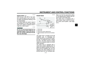
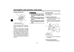
EAU12830
Clutch lever The clutch lever is located at the left
handlebar grip. To disengage the
clutch, pull the lever toward the handle-
bar grip. To engage the clutch, release
the lever. The lever should be pulled
rapidly and released slowly for smooth
clutch operation.
The clutch lever is equipped with a
clutch lever position adjusting dial. To
adjust the distance between the clutch
lever and the handlebar grip, turn the
adjusting dial while holding the lever
pushed away from the handlebar grip.Make sure that the appropriate setting
on the adjusting dial is aligned with the
arrow mark on the clutch lever.
The clutch lever is equipped with a
clutch switch, which is part of the igni-
tion circuit cut-off system. (See page
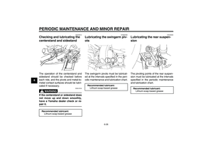
3-31.)1. Clutch lever
2. Arrow mark
3. Clutch lever position adjusting dial
4. Distance between clutch lever and handlebar
grip
U3P6E2E0.book Page 15 Friday, September 14, 2007 9:43 AM
Page 30 of 102

INSTRUMENT AND CONTROL FUNCTIONS
3-16
3
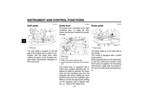
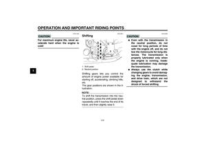
EAU12870
Shift pedal The shift pedal is located on the left
side of the engine and is used in com-
bination with the clutch lever when
shifting the gears of the 5-speed con-
stant-mesh transmission equipped on
this motorcycle.
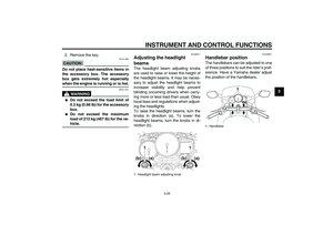
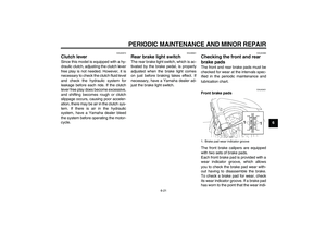
EAU26823
Brake lever The brake lever is located at the right
handlebar grip. To apply the front
brake, pull the lever toward the handle-
bar grip.
The brake lever is equipped with a
brake lever position adjusting dial. To
adjust the distance between the brake
lever and the handlebar grip, turn the
adjusting dial while holding the lever
pushed away from the handlebar grip.
Make sure that the appropriate setting
on the adjusting dial is aligned with
the“” mark on the brake lever.
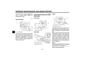
EAU39540
Brake pedal The brake pedal is on the right side of
the vehicle.
This model is equipped with a unified
brake system.
When pressing down on the brake ped-
al, the rear brake and a portion of the
front brake are applied. For full braking
performance, apply both the brake le-
ver and the brake pedal simultaneous-
ly.
1. Shift pedal
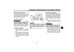
1. Brake lever
2.“” mark
3. Brake lever position adjusting dial
4. Distance between brake lever and handlebar
grip
1. Brake pedal
U3P6E2E0.book Page 16 Friday, September 14, 2007 9:43 AM
Page 31 of 102
 features a dual electronic con-
trol system, which acts on the front and
rear brakes independently. The ABS")
INSTRUMENT AND CONTROL FUNCTIONS
3-17
3
EAU39531
ABS The Yamaha ABS (Anti-lock Brake
System) features a dual electronic con-
trol system, which acts on the front and
rear brakes independently. The ABS is
monitored by an ECU (Electronic Con-
trol Unit), which will have recourse to
manual braking if a malfunction occurs.
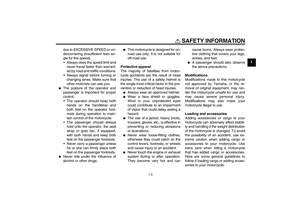
WARNING
EWA10090
�
The ABS performs best on long
braking distances.
�
On certain (rough or gravel)
roads, the braking distance may
be longer with than without the
ABS. Therefore, always keep a
sufficient distance to the vehicle
ahead to match the ridingspeed.
NOTE:�
The ABS performs a self-diagno-
sis test for a few seconds each
time the vehicle first starts off after
the main switch was turned on.
During this test, a “clicking” noise
can be heard from under the seat,
and if the brake lever or brake ped-al are even slightly applied, a vi-
bration can be felt at the lever and
pedal, but these do not indicate a
malfunction.
�
When the ABS is activated, the
brakes are operated in the usual
way. A pulsating action may be felt
at the brake lever or brake pedal,
but this does not indicate a mal-
function.
�
This ABS has a test mode which
allows the owner to experience the
pulsating at the brake lever or
brake pedal when the ABS is oper-
ating. However, special tools are
required, so please consult your
Yamaha dealer when performingthis test.
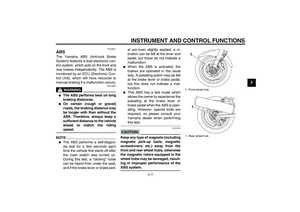
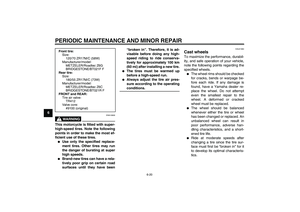
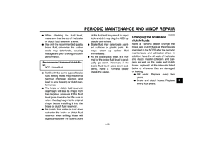
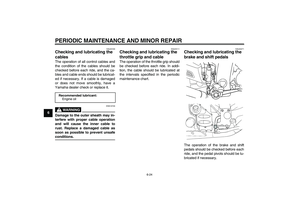
CAUTION:
ECA16120
Keep any type of magnets (including
magnetic pick-up tools, magnetic
screwdrivers, etc.) away from the
front and rear wheel hubs, otherwise
the magnetic rotors equipped in the
wheel hubs may be damaged, result-
ing in improper performance of theABS system.
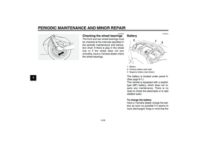
1. Front wheel hub
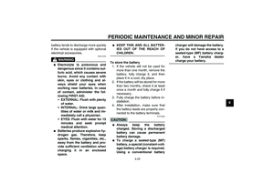
1. Rear wheel hub
11
U3P6E2E0.book Page 17 Friday, September 14, 2007 9:43 AM
Page 32 of 102

INSTRUMENT AND CONTROL FUNCTIONS
3-18
3
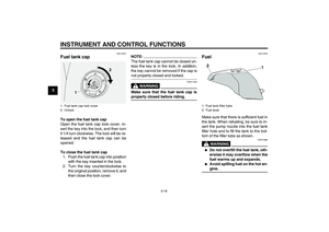
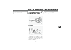
EAU13072
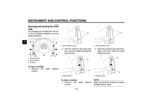
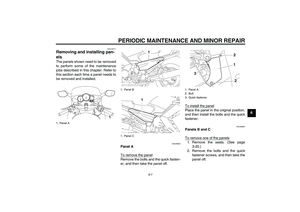
Fuel tank cap To open the fuel tank cap
Open the fuel tank cap lock cover, in-
sert the key into the lock, and then turn
it 1/4 turn clockwise. The lock will be re-
leased and the fuel tank cap can be
opened.
To close the fuel tank cap
1. Push the fuel tank cap into position
with the key inserted in the lock.
2. Turn the key counterclockwise to
the original position, remove it, and
then close the lock cover.
NOTE:The fuel tank cap cannot be closed un-
less the key is in the lock. In addition,
the key cannot be removed if the cap isnot properly closed and locked.
WARNING
EWA11090
Make sure that the fuel tank cap isproperly closed before riding.
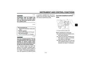
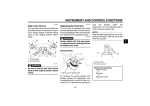
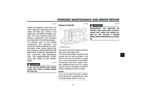
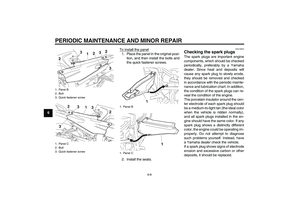
EAU13220
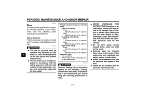
Fuel Make sure that there is sufficient fuel in
the tank. When refueling, be sure to in-
sert the pump nozzle into the fuel tank
filler hole and to fill the tank to the bot-
tom of the filler tube as shown.
WARNING
EWA10880
�
Do not overfill the fuel tank, oth-
erwise it may overflow when the
fuel warms up and expands.
�
Avoid spilling fuel on the hot en-gine.
1. Fuel tank cap lock cover
2. Unlock.
1. Fuel tank filler tube
2. Fuel level
U3P6E2E0.book Page 18 Friday, September 14, 2007 9:43 AM