Page 257 of 496
245
USING THE CONTROLLER
To use the rear seat entertainment sys-
tem controller, direct the signal output
portion of the controller to the signal
reception portion of the rear seat enter-
tainment system display.
The controller does not operate properly
when the signal reception portion of the
display is exposed to direct sunlight.
Block the display from direct sunlight.
CAUTION
To reduce the chance of injury in
case of an accident or a sudden stop
while driving, stow the controller in
the console box or front seat side
table when it is not in use.
NOTICE
Observe the followings, otherwise the
controller may be damaged.
�Do not drop or strongly knock the
controller against hard objects.
� Do not sit on or place heavy ob-
jects on the controller.
� Do not leave the controller exposed
to high temperatures (such as on
the instrument panel) for a long
time.
Page 291 of 496
279
CY19135
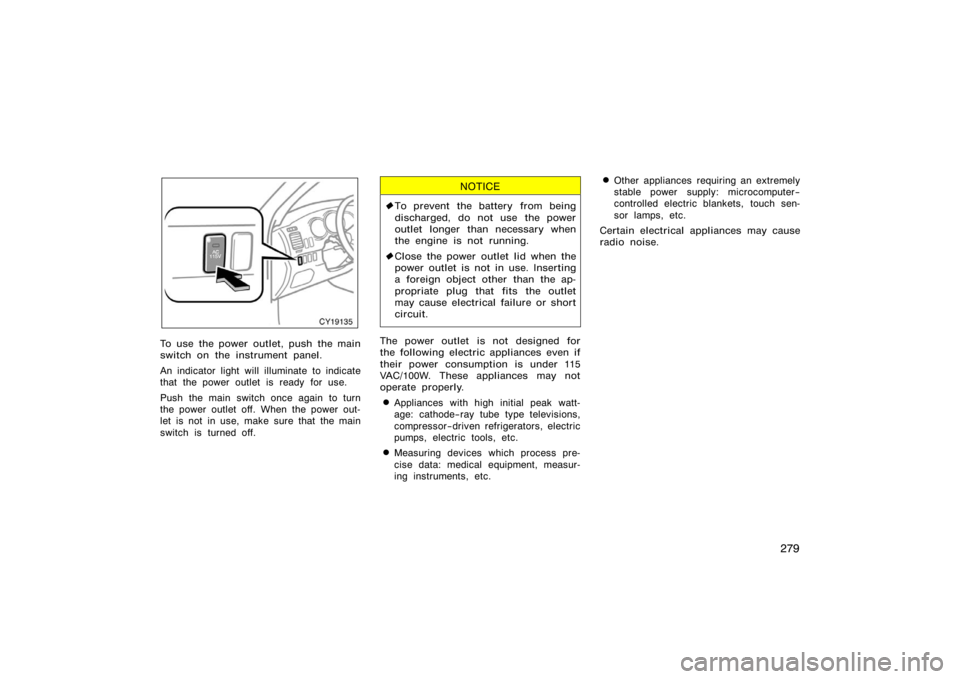
To use the power outlet, push the main
switch on the instrument panel.
An indicator light will illuminate to indicate
that the power outlet is ready for use.
Push the main switch once again to turn
the power outlet off. When the power out-
let is not in use, make sure that the main
switch is turned off.
NOTICE
�To prevent the battery from being
discharged, do not use the power
outlet longer than necessary when
the engine is not running.
� Close the power outlet lid when the
power outlet is not in use. Inserting
a foreign object other than the ap-
propriate plug that fits the outlet
may cause electrical failure or short
circuit.
The power outlet is not designed for
the following electric appliances even if
their power consumption is under 115
VAC/100W. These appliances may not
operate properly.
�Appliances with high initial peak watt-
age: cathode−ray tube type televisions,
compressor−driven refrigerators, electric
pumps, electric tools, etc.
�Measuring devices which process pre-
cise data: medical equipment, measur-
ing instruments, etc.
�Other appliances requiring an extremely
stable power supply: microcomputer−
controlled electric blankets, touch sen-
sor lamps, etc.
Certain electrical appliances may cause
radio noise.
Page 301 of 496
289
OPERATION OF INSTRUMENTS AND
CONTROLS
Air conditioning system
Controls290
. . . . . . . . . . . . . . . . . . . . . . . . . . . . . . . . . . . . .\
. . . . . . . . . . . . . .
Air flow selector settings 296
. . . . . . . . . . . . . . . . . . . . . . . . . . . . . . . . . . . . \
.
Operating tips 296
. . . . . . . . . . . . . . . . . . . . . . . . . . . . . . . . . . . . \
. . . . . . . . . .
Instrument panel and rear vents 299
. . . . . . . . . . . . . . . . . . . . . . . . . . . . . .
Air conditioning filter 300
. . . . . . . . . . . . . . . . . . . . . . . . . . . . . . . . . . . . \
. . . .
SECTION 1− 9
Page 303 of 496
291
�AUTO" button
For automatic operation of the air condi-
tioning, push the �AUTO" button. An indi-
cator light will illuminate to show that the
automatic operation mode has been se-
lected.
In the automatic operation mode, the air
conditioning selects the most suitable fan
speed, air flow, air intake and on−off of
the air conditioning according to the tem-
perature.
When you push the �AUTO" button with
the air intake mode at FRESH, internal
circulation may be applied for maximum
cooling.
You may use manual controls if you want
to select your own settings.
Fan speed selector
Select the mode button you desire to ad-
just the fan speed and push it. An indica-
tor light will illuminate to show which fan
speed mode is being selected.
In automatic operation, you do not have
to adjust the fan speed unless you desire
another fan speed mode.Temperature selector
To increase the temperature, push the
�UP" side, to decrease it, push the
�DOWN" side.
�LO" appears when you adjust to maxi-
mum cooling, and �HI" appears when you
adjust to maximum warming.
�OFF" button
Push the �OFF" button to turn off the air
conditioning system.
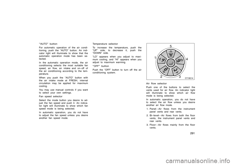
CY18014
Air flow selector
Push one of the buttons to select the
vents used for air flow. An indicator light
will illuminate to show which air flow
mode is being selected.
In automatic operation, you do not have
to select the air flow unless you desire
another air flow mode.
1. Panel� Air flows from the instrument
panel vents and rear vents.
2. Bi−level� Air flows from both the floor
vents, the instrument panel vents and
rear vents.
3. Floor� Air flows mainly from the floor
vents.
Page 306 of 496
294
�AUTO" button
For automatic operation of the air condi-
tioning, push the �AUTO" button. An indi-
cator light will illuminate to show that the
automatic operation mode has been se-
lected.
In the automatic operation mode, the air
conditioning selects the most suitable fan
speed, air flow, air intake and on−off of
the air conditioning according to the tem-
perature.
When you push the �AUTO" button with
the air intake mode at FRESH, internal
circulation may be applied for maximum
cooling.
You may use manual controls if you want
to select your own settings.
Fan speed selector
Select the mode button you desire to ad-
just the fan speed and push it. An indica-
tor light will illuminate to show which fan
speed mode is being selected.
In automatic operation, you do not have
to adjust the fan speed unless you desire
another fan speed mode.Temperature selector
To increase the temperature, push the �
�"
side, to decrease it, push the � �" side.
�LO" appears when you adjust to maxi-
mum cooling, and �HI" appears when you
adjust to maximum warming.
�DUAL" button
This button is used to set the tempera-
tures independently for the driver ’s seat
and front passenger seat.
Pushing the button changes the mode
from independent and linked.
Independent mode: Temperatures can be
set independently for the driver ’s seat and
front passenger ’s seat. An indicator light
will illuminated to show that the indepen-
dent mode has been selected.
Linked mode: The same temperature is
set for the driver’s seat and front passen-
ger ’s seat.
When the temperature for the front pas-
senger ’s seat is changed in linked mode,
the mode is changed automatically to in-
dependent mode.
�OFF" button
Push the �OFF" button to turn off the air
conditioning system.
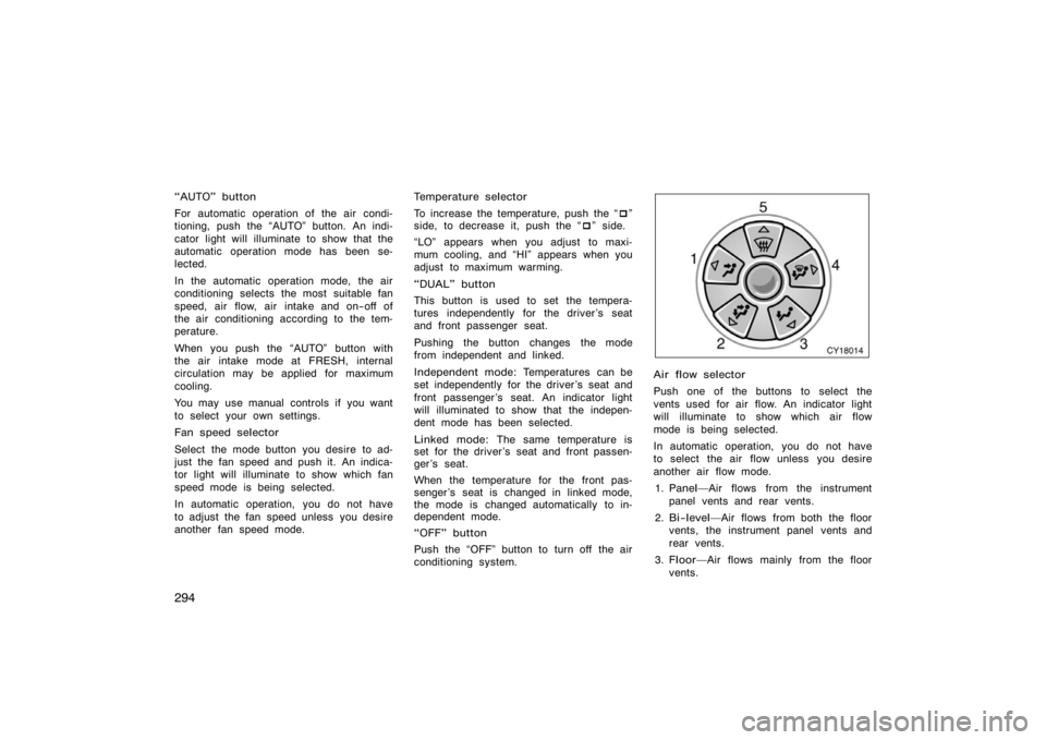
CY18014
Air flow selector
Push one of the buttons to select the
vents used for air flow. An indicator light
will illuminate to show which air flow
mode is being selected.
In automatic operation, you do not have
to select the air flow unless you desire
another air flow mode.
1. Panel� Air flows from the instrument
panel vents and rear vents.
2. Bi−level� Air flows from both the floor
vents, the instrument panel vents and
rear vents.
3. Floor� Air flows mainly from the floor
vents.
Page 311 of 496
299
Pressing the windshield air flow button
turns on the defogging function with the
purpose of clearing the front view.
When pressing the windshield air flow but-
ton, the air intake selects FRESH auto-
matically. This is to clean up the front
view more quickly.
It is not possible to return to RECIRCU-
LATE in this mode.
Press the �A/C" button for dehumidified
heating or cooling. This setting clears the
front view more quickly.
�To heat the vehicle interior while de-
frosting the windshield, choose
floor/windshield air flow.
CY18006
Center vents
CY18005
Side vents
CY18017
Rear vents
If air flow control is not satisfactory, check
the instrument panel and rear vents. The
instrument panel and rear vents may be
opened or closed as shown.
Instrument panel and rear
vents
Page 328 of 496
316
NOTICE
�To prevent the fuse from being
blown, do not use the electricity
over the total vehicle capacity of 12
VDC/120W.
� To prevent the battery from being
discharged, do not use the power
outlets longer than necessary when
the engine is not running.
� Close the power outlet lids when
the power outlets are not in use.
Inserting anything other than an ap-
propriate plug that fits the outlet,
or allowing any liquid to get into
the outlet may cause electrical fail-
ure or short circuits.
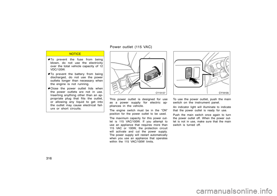
CY19137
This power outlet is designed for use
as a power supply for electric ap-
pliances in the vehicle.
The engine switch must be in the �ON"
position for the power outlet to be used.
The maximum capacity for this power out-
let is 115 VAC/100W. If you attempt to
use an appliance that requires more than
115 VAC or 100W, the protection circuit
will activate and cut the power supply.
The power supply will restart automatically
when you use an appliance that operates
within the 115 VAC/100W limits.
CY19135
To use the power outlet, push the main
switch on the instrument panel.
An indicator light will illuminate to indicate
that the power outlet is ready for use.
Push the main switch once again to turn
the power outlet off. When the power out-
let is not in use, make sure that the main
switch is turned off.
Power outlet (115 VAC)
Page 329 of 496
317
NOTICE
�To prevent the battery from being
discharged, do not use the power
outlet longer than necessary when
the engine is not running.
� Close the power outlet lid when the
power outlet is not in use. Inserting
anything other than an appropriate
plug that fits the outlet may cause
electrical failure or short circuits.
The power outlet is not designed for
the following electric appliances even
though their power consumption is un-
der 115 VAC/100W. These appliances
may not operate properly.
�Appliances with high initial peak watt-
age: cathode−ray tube type televisions,
compressor−driven refrigerators, electric
pumps, electric tools, etc.
�Measuring devices which process pre-
cise data: medical equipment, measur-
ing instruments, etc.
�Other appliances requiring an extremely
stable power supply: microcomputer−
controlled electric blankets, touch sen-
sor lamps, etc.
Certain electrical appliances may cause
radio noise.
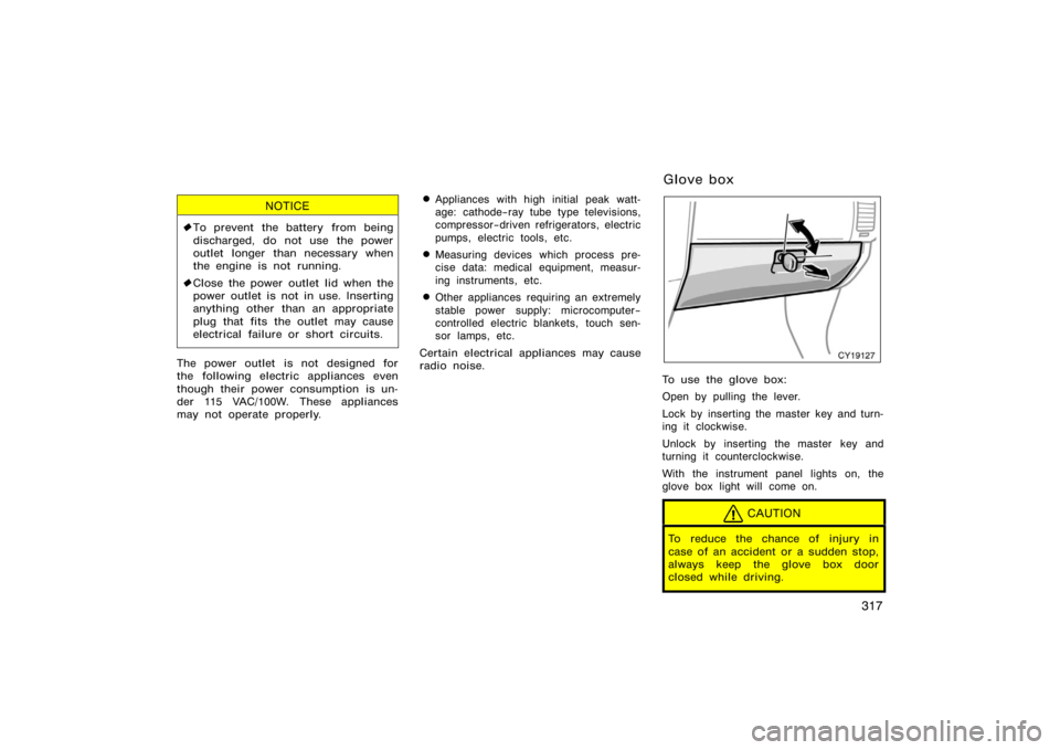
CY19127
To use the glove box:
Open by pulling the lever.
Lock by inserting the master key and turn-
ing it clockwise.
Unlock by inserting the master key and
turning it counterclockwise.
With the instrument panel lights on, the
glove box light will come on.
CAUTION
To reduce the chance of injury in
case of an accident or a sudden stop,
always keep the glove box door
closed while driving.
Glove box