2008 SUZUKI SX4 light
[x] Cancel search: lightPage 189 of 278

INSPECTION AND MAINTENANCE
9
80J21-03E
60G410
INSPECTION AND MAINTENANCEMaintenance Schedule ....................................................... 9-2
Periodic Maintenance Schedule ........................................ 9-3
Maintenance Recommended under Severe Driving
Conditions ........................................................................... 9-7
Engine Oil and Filter ........................................................... 9-11
Gear Oil ................................................................................ 9-14
Automatic Transaxle Fluid ................................................. 9-16
Engine Coolant .................................................................... 9-17
Windshield Washer Fluid ................................................... 9-19
Air Cleaner ........................................................................... 9-19
Spark Plugs ......................................................................... 9-20
Brakes .................................................................................. 9-21
Steering Wheel .................................................................... 9-23
Clutch Pedal ........................................................................ 9-24
Tires ...................................................................................... 9-24
Battery .................................................................................. 9-35
Fuses .................................................................................... 9-35
Headlight Aiming ................................................................. 9-39
Bulb Replacement ............................................................... 9-39
Wiper Blades ....................................................................... 9-44
Air Conditioning System .................................................... 9-48
Page 210 of 278
9-21INSPECTION AND MAINTENANCE
80J21-03E
BrakesBrake Fluid
80J004
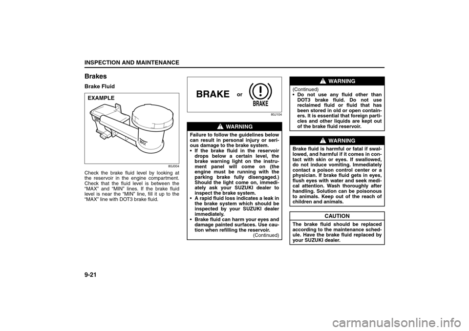
Check the brake fluid level by looking at
the reservoir in the engine compartment.
Check that the fluid level is between the
“MAX” and “MIN” lines. If the brake fluid
level is near the “MIN” line, fill it up to the
“MAX” line with DOT3 brake fluid.
80J104
EXAMPLE
WARNING
Failure to follow the guidelines below
can result in personal injury or seri-
ous damage to the brake system.
If the brake fluid in the reservoir
drops below a certain level, the
brake warning light on the instru-
ment panel will come on (the
engine must be running with the
parking brake fully disengaged.)
Should the light come on, immedi-
ately ask your SUZUKI dealer to
inspect the brake system.
A rapid fluid loss indicates a leak in
the brake system which should be
inspected by your SUZUKI dealer
immediately.
Brake fluid can harm your eyes and
damage painted surfaces. Use cau-
tion when refilling the reservoir.
(Continued)
or
WARNING
(Continued)
Do not use any fluid other than
DOT3 brake fluid. Do not use
reclaimed fluid or fluid that has
been stored in old or open contain-
ers. It is essential that foreign parti-
cles and other liquids are kept out
of the brake fluid reservoir.
WARNING
Brake fluid is harmful or fatal if swal-
lowed, and harmful if it comes in con-
tact with skin or eyes. If swallowed,
do not induce vomiting. Immediately
contact a poison control center or a
physician. If brake fluid gets in eyes,
flush eyes with water and seek medi-
cal attention. Wash thoroughly after
handling. Solution can be poisonous
to animals. Keep out of the reach of
children and animals.
CAUTION
The brake fluid should be replaced
according to the maintenance sched-
ule. Have the brake fluid replaced by
your SUZUKI dealer.
Clutch Pedal: 6
Tires: 6
Page 212 of 278
9-23INSPECTION AND MAINTENANCE
80J21-03E
Parking Brake Lever
60A226
Check the parking brake for proper adjust-
ment by counting the number of clicks
made by the ratchet teeth as you slowly
pull up on the parking brake lever to the
point of full engagement. The parking
brake lever should stop between the speci-
fied ratchet teeth and the rear wheels
should be securely locked. If the parking
brake is not properly adjusted or the
brakes drag after the lever has been fully
released, have the parking brake inspected
and/or adjusted by your SUZUKI dealer.
Steering Wheel
80J005
Check the play of the steering wheel by
gently turning it from left to right and mea-
suring the distance that it moves before
you feel slight resistance. The play should
be between the specified values. Check
that the steering wheel turns easily and
smoothly without rattling by turning it all the
way to the right and to the left while driving
very slowly in an open area. If the amount
of free play is outside the specification or
you find anything else to be wrong, an
inspection must be performed by your
SUZUKI dealer.
Power Steering (if equipped)
54G225
(1) UPPER
(2) LOWER
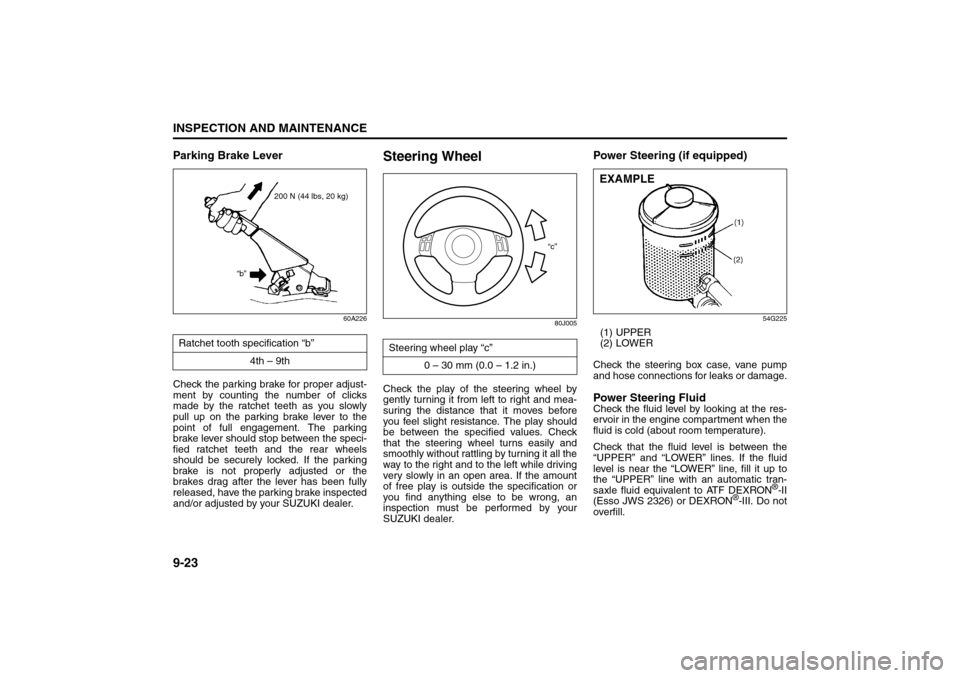
Check the steering box case, vane pump
and hose connections for leaks or damage.Power Steering FluidCheck the fluid level by looking at the res-
ervoir in the engine compartment when the
fluid is cold (about room temperature).
Check that the fluid level is between the
“UPPER” and “LOWER” lines. If the fluid
level is near the “LOWER” line, fill it up to
the “UPPER” line with an automatic tran-
saxle fluid equivalent to ATF DEXRON
®-II
(Esso JWS 2326) or DEXRON
®-III. Do not
overfill. Ratchet tooth specification “b”
4th – 9th
200 N (44 lbs, 20 kg)
“b”
Steering wheel play “c”
0 – 30 mm (0.0 – 1.2 in.)
“c”
EXAMPLE
Tires: 6
Page 215 of 278
9-26
INSPECTION AND MAINTENANCE
80J21-03E
Tire Inflation PressureTire inflation pressure should be checked
when the tire is cold. “Cold tire inflation
pressure” is the pressure in a tire that has
been driven less than 1 mile (1.6 km) or
has been standing for three hours or more.
80JS025
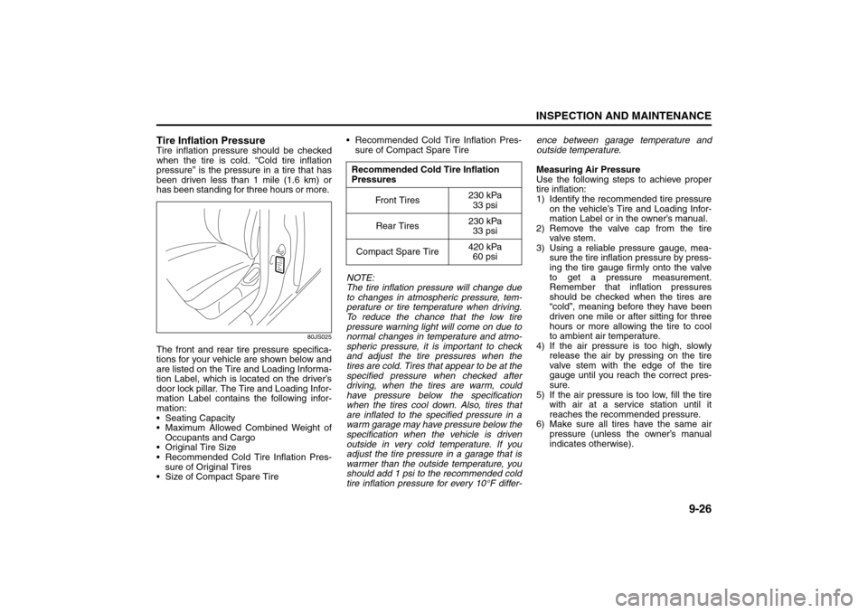
The front and rear tire pressure specifica-
tions for your vehicle are shown below and
are listed on the Tire and Loading Informa-
tion Label, which is located on the driver’s
door lock pillar. The Tire and Loading Infor-
mation Label contains the following infor-
mation:
Seating Capacity
Maximum Allowed Combined Weight of
Occupants and Cargo
Original Tire Size
Recommended Cold Tire Inflation Pres-
sure of Original Tires
Size of Compact Spare Tire Recommended Cold Tire Inflation Pres-
sure of Compact Spare Tire
NOTE:
The tire inflation pressure will change due
to changes in atmospheric pressure, tem-
perature or tire temperature when driving.
To reduce the chance that the low tire
pressure warning light will come on due to
normal changes in temperature and atmo-
spheric pressure, it is important to check
and adjust the tire pressures when the
tires are cold. Tires that appear to be at the
specified pressure when checked after
driving, when the tires are warm, could
have pressure below the specification
when the tires cool down. Also, tires that
are inflated to the specified pressure in a
warm garage may have pressure below the
specification when the vehicle is driven
outside in very cold temperature. If you
adjust the tire pressure in a garage that is
warmer than the outside temperature, you
should add 1 psi to the recommended cold
tire inflation pressure for every 10°F differ-ence between garage temperature and
outside temperature.
Measuring Air Pressure
Use the following steps to achieve proper
tire inflation:
1) Identify the recommended tire pressure
on the vehicle’s Tire and Loading Infor-
mation Label or in the owner’s manual.
2) Remove the valve cap from the tire
valve stem.
3) Using a reliable pressure gauge, mea-
sure the tire inflation pressure by press-
ing the tire gauge firmly onto the valve
to get a pressure measurement.
Remember that inflation pressures
should be checked when the tires are
“cold”, meaning before they have been
driven one mile or after sitting for three
hours or more allowing the tire to cool
to ambient air temperature.
4) If the air pressure is too high, slowly
release the air by pressing on the tire
valve stem with the edge of the tire
gauge until you reach the correct pres-
sure.
5) If the air pressure is too low, fill the tire
with air at a service station until it
reaches the recommended pressure.
6) Make sure all tires have the same air
pressure (unless the owner’s manual
indicates otherwise).
Recommended Cold Tire Inflation
Pressures
Fr on t T ir es230 kPa
33 psi
Rear Tires230 kPa
33 psi
Compact Spare Tire420 kPa
60 psi
Tires: 6
Page 219 of 278
9-30
INSPECTION AND MAINTENANCE
80J21-03E
Compact Spare Tire (if equipped)
54G115
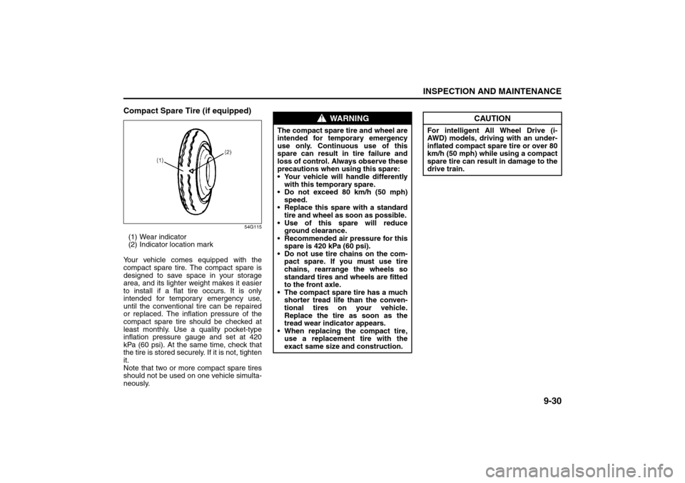
(1) Wear indicator
(2) Indicator location mark
Your vehicle comes equipped with the
compact spare tire. The compact spare is
designed to save space in your storage
area, and its lighter weight makes it easier
to install if a flat tire occurs. It is only
intended for temporary emergency use,
until the conventional tire can be repaired
or replaced. The inflation pressure of the
compact spare tire should be checked at
least monthly. Use a quality pocket-type
inflation pressure gauge and set at 420
kPa (60 psi). At the same time, check that
the tire is stored securely. If it is not, tighten
it.
Note that two or more compact spare tires
should not be used on one vehicle simulta-
neously.
WARNING
The compact spare tire and wheel are
intended for temporary emergency
use only. Continuous use of this
spare can result in tire failure and
loss of control. Always observe these
precautions when using this spare:
Your vehicle will handle differently
with this temporary spare.
Do not exceed 80 km/h (50 mph)
speed.
Replace this spare with a standard
tire and wheel as soon as possible.
Use of this spare will reduce
ground clearance.
Recommended air pressure for this
spare is 420 kPa (60 psi).
Do not use tire chains on the com-
pact spare. If you must use tire
chains, rearrange the wheels so
standard tires and wheels are fitted
to the front axle.
The compact spare tire has a much
shorter tread life than the conven-
tional tires on your vehicle.
Replace the tire as soon as the
tread wear indicator appears.
When replacing the compact tire,
use a replacement tire with the
exact same size and construction.
CAUTION
For intelligent All Wheel Drive (i-
AWD) models, driving with an under-
inflated compact spare tire or over 80
km/h (50 mph) while using a compact
spare tire can result in damage to the
drive train.
Tires: 6
Page 223 of 278

9-34
INSPECTION AND MAINTENANCE
80J21-03E
Steps for Determining Correct Load
Limit
1) Locate the statement “The combined
weight of occupants and cargo should
never exceed XXX kg or XXX lbs” on
your vehicle’s placard.
2) Determine the combined weight of the
driver and passengers that will be riding
in your vehicle.
3) Subtract the combined weight of the
driver and passengers from XXX kg or
XXX lbs.
4) The resulting figure equals the available
amount of cargo and luggage load
capacity. For example, if the “XXX”
amount equals 1400 lbs and there will
be five 150 lb passengers in your vehi-
cle, the amount of available cargo and
luggage load capacity is 650 lbs (1400
– 750 (5 x 150) = 650 lbs).
5) Determine the combined weight of lug-
gage and cargo being loaded on the
vehicle. That weight may not safely
exceed the available cargo and luggage
load capacity calculated in Step 4.
6) If your vehicle will be towing a trailer,
load from your trailer will be transferred
to your vehicle. Consult this manual to
determine how this reduces the avail-
able cargo and luggage load capacity of
your vehicle.Vehicle Loading Example
As an example, suppose that the Tire and
Loading Information label on your vehicle
indicates that your vehicle’s total load
capacity is 950 lbs. If you were to drive
your vehicle with one passenger, and the
total combined weight of you and your pas-
senger was 350 lbs, then the cargo and
luggage capacity of your vehicle would be
600 lbs (950 – 350 = 600 lbs).
If you later added 2 more passengers, hav-
ing a combined weight of 325 lbs, the
cargo and luggage capacity of your vehicle
would be reduced from 600 lbs to 275 lbs
(600 – 325 = 275 lbs). As you can see, as
the number and combined weight of vehi-
cle occupants increase, the vehicle’s cargo
and luggage capacity decreases.
Suppose again, that you were to take a trip
in your vehicle with the same three pas-
sengers described above, and you decided
to tow a trailer having a trailer tongue
weight of 75 lbs. The cargo and luggage
capacity would be reduced again, to 200
lbs (275 – 75 = 200 lbs).Determining Compatibility of Tire and
Vehicle Load Limits
The tires on your vehicle, when they are
inflated to the recommended tire inflation
pressure, have a load-carrying capacity
that is greater than the load that will be on
the tires when the vehicle is at its GVWR
or GAWR limit. Never use replacement
tires that have a load-carrying capacity
less than the original tires on your vehicle.
Tire load-carrying capacity information is
molded into the tire sidewall typically
shown as “Max. Load”. Use of replacement
tires with a lower load-carrying capacity
than the original tires, or failure to keep the
tires inflated to recommended tire pres-
sure, may reduce the GVWR or GAWR
limit of your vehicle.
NOTE:
Use of replacement tires with a higher
load-carrying capacity than the original
tires, or using a tire inflation pressure
higher than the recommended tire inflation
pressure, will not increase the GVWR or
GAWR limit of your vehicle.
Headlight Aiming:
Bulb Replacement: 7
Page 225 of 278

9-36
INSPECTION AND MAINTENANCE
80J21-03E
Fuses in the Engine Compartment
80J051
80J052
(1)
(2) (3)
(28) (27) (26) (25) (6) (7) (9) (11)
(15) (16) (17) (18) (19)
(24)
(8) (4) (5) (10)
(22) (21)
(23)(20)(12) (13) (14)
(30)
(29)
MAIN FUSE / PRIMARY FUSE
(1) 80A All electric load
(2) 50APower window, Ignition,
Wiper, Starter
(3) 50ATail light, Rear defogger,
Door lock, Hazard/Horn,
Dome
(4) – Blank
(5) – Blank
(6) 15A Head light (Right) fuse
(7) 15A Head light (Left) fuse
(8) 20A Front fog light fuse
(9) – Blank
(10) 40A ABS control module fuse
(11) 30A Radiator fan fuse
(12) 30A ABS control module fuse
(13) 30A Starting motor fuse
(14) 50A Ignition switch fuse
(15) 30A Blower fan fuse
(16) 20A Air compressor fuse
(17) 15A Throttle motor fuse
(18) 15A Automatic transaxle fuse
(19) 15A Fuel injection fuse
(20) – Automatic transaxle relay
(21) – Air compressor relay
(22) – Fuel pump relay
(23) – Condenser fan relay
(24) – Front fog light relay
(25) – Throttle motor relay
(26) – FI MAIN
(27) – Starting motor relay
(28) – Radiator fan relay
(29) – Radiator fan relay 2
(30) – Radiator fan relay 3
Bulb Replacement: 7
Page 226 of 278
9-37INSPECTION AND MAINTENANCE
80J21-03E
60A243
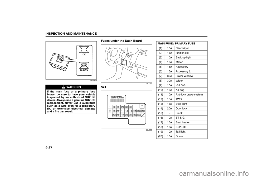
Fuses under the Dash Board
79J093
SX4
80J053
WARNING
If the main fuse or a primary fuse
blows, be sure to have your vehicle
inspected by an authorized SUZUKI
dealer. Always use a genuine SUZUKI
replacement. Never use a substitute
such as a wire even for a temporary
fix, or extensive electrical damage
and a fire can result.
BLOWNOK
(1) (2) (3) (4) (5) (6)
(8) (9) (10) (11) (12) (13) (14) (15) (16)
(18) (17) (19) (20) (21) (22) (23)(7)
MAIN FUSE / PRIMARY FUSE
(1) 15A Rear wiper
(2) 15A Ignition coil
(3) 10A Back-up light
(4) 10A Meter
(5) 15A Accessory
(6) 15A Accessory 2
(7) 30A Power window
(8) 30A Wiper
(9) 10A IG1 SIG
(10) 15A Air bag
(11) 10A Anti-lock brake system
(12) 15A 4WD
(13) 15A Stop light
(14) 20A Door lock
(15) – Blank
(16) 10A ST SIG
(17) 15A Seat heater
(18) 10A IG 2 SIG
(19) 10A Tail light
(20) 15A Dome
Bulb Replacement: 7