2008 SUZUKI SWIFT tail
[x] Cancel search: tailPage 891 of 1496

Downloaded from www.Manualslib.com manuals search engine Power Assisted Steering System: 6C-9
3) Start engine.
4) Read DTC according to the instructions displayed on
SUZUKI scan tool. For further details, refer to
operator’s manual for SUZUKI scan tool.
NOTE
• If communication between SUZUKI scan tool and the vehicle can not be
established, perform “Serial Data Link
Circuit Check”.
• DTC C1122 (engine speed signal failure) is indicated when ignition switch is at ON
position and engine is not running, but it
means there is nothing abnormal if
indication changes to a normal one when
engine is started.
5) After completing the check, turn ignition switch to
OFF position and disconnect SUZUKI scan tool from
DLC.
DTC ClearanceS7RS0B6304004
1) Turn ignition switch to OFF position.
2) Connect SUZUKI scan tool to data link connector (DLC) (1) located on underside of instrument panel
at driver’s seat side.
Special tool
(A): SUZUKI scan tool
3) Turn ignition switch to ON position.
4) Erase DTC according to the instructions displayed on SUZUKI scan tool. For further details, refer to
operator’s manual for SUZUKI scan tool.
5) After completing the clearance, turn ignition switch to OFF position and disconnect SUZUKI scan tool from
DLC.
DTC TableS7RS0B6304005
CAUTION!
Be sure to perform the “EPS Syst em Check” before starting troubleshooting corresponding to each
DTC.
(A)
1
I4RS0B450003-01
DTC No. Detecting item Detecting condition
(DTC will set when detecting) Trouble area MIL
No
CODES Normal — — —
�) C1113 Steering torque sensor (Main
and Sub) circuit correlation Voltage difference between torque
sensor main signal and sub signal
is more than 0.6 V for 1 second
continuously. • Torque sensor signal circuit
• Torque sensor
• P/S control module
1 driving
cycle
�) C1114 Steering torque sensor
reference power supply
circuit Circuit voltage of torque sensor 5
V reference power supply voltage
is more than 5.7 V or less than 4.3
V for 1 second continuously. • Torque sensor circuit
• Torque sensor
• P/S control module
1 driving
cycle
�) C1117 Steering torque sensor
failure signal circuit low Torque sensor internal failure
signal circuit voltage is less than
1.7 V when ignition switch turned
ON.
• Torque sensor signal circuit
• Torque sensor
• P/S control module1 driving
cycle
�) C1118 Steering torque sensor
failure signal circuit high Torque sensor internal failure
signal circuit voltage is more than
3.7 V for 1 second continuously. 1 driving
cycle
�) C1119 Steering torque sensor
power supply circuit Circuit voltage of torque sensor
main power supply
is less than
7.5 V for 1 second continuously. • Torque sensor circuit
• Torque sensor
• P/S control module
1 driving
cycle
Page 961 of 1496
Downloaded from www.Manualslib.com manuals search engine Air Conditioning System: Manual Type 7B-13
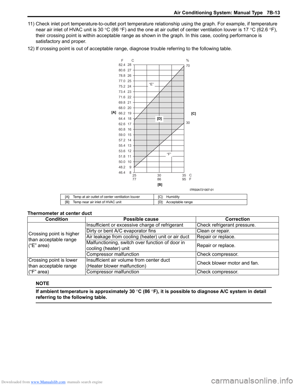
11) Check inlet port temperature-to-outlet port temperature relationship using the graph. For example, if temperature
near air inlet of HVAC unit is 30 °C (86 °F) and the one at air outlet of center ventilation louver is 17 °C (62.6 °F),
their crossing point is within acceptable range as shown in the graph. In this case, cooling performance is
satisfactory and proper.
12) If crossing point is out of acceptable range, diagnose trouble referring to the following table.
Thermometer at center duct
NOTE
If ambient temperature is approximately 30 °C (86 °F), it is possible to diagnose A/C system in detail
referring to the following table.
[A]: Temp at air outlet of center ventilation louver [C]: Humidity
[B]: Temp near air inlet of HVAC unit [D]: Acceptable range
ConditionPossible cause Correction
Crossing point is higher
than acceptable range
(“E” area) Insufficient or excessive charge of refrigerant Check refrigerant pressure.
Dirty or bent A/C evaporator fins
Clean or repair.
Air leakage from cooling (heater) unit or air duct Repair or replace.
Malfunctioning, switch over function of door in
cooling (heater) unit Repair or replace.
Compressor malfunct ion Check compressor.
Crossing point is lower
than acceptable range
(“F” area) Insufficient air volume from center duct
(Heater blower malfunction)
Check blower motor and fan.
Compressor malfunct ion Check compressor.
8 9
10 11 12 13 14
15 16 17 18 19
20
21
22
23
24
25 26
27
28
46.4 48.2 50.0 51.8 53.6 55.4 57.2 59.0 60.8 62.6 64.4
66.2 68.0
69.8
71.6
73.4
75.2
77.0
78.8 80.6
82.4
25 30 35
77 86 95
F C
C
F
“E”
“F”30 70 %
[A]
[B][C]
[D]
I7RS0A721007-01
Page 962 of 1496
Downloaded from www.Manualslib.com manuals search engine 7B-14 Air Conditioning System: Manual Type
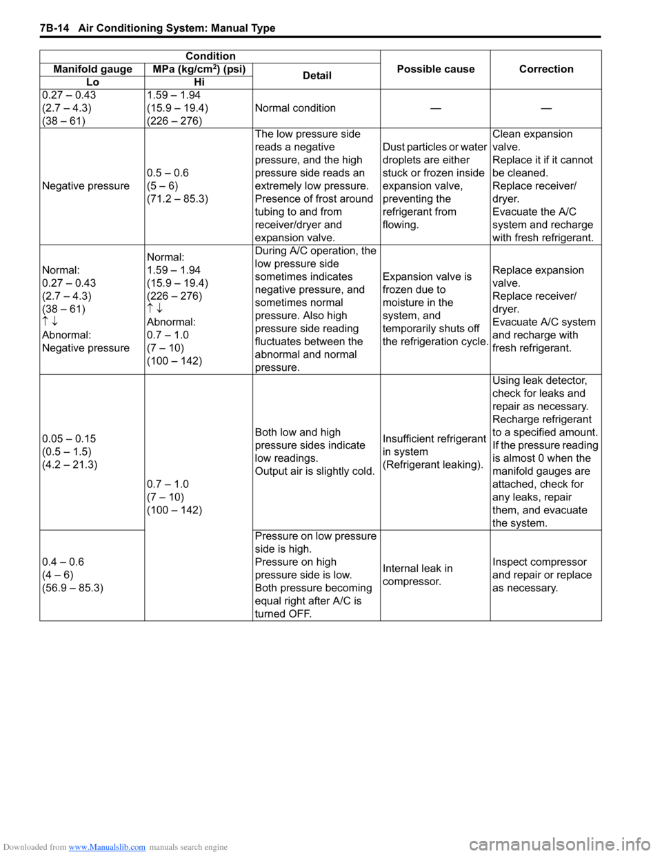
ConditionPossible cause Correction
Manifold gauge MPa (kg/cm2) (psi)
Detail
Lo Hi
0.27 – 0.43
(2.7 – 4.3)
(38 – 61) 1.59 – 1.94
(15.9 – 19.4)
(226 – 276)
Normal condition — —
Negative pressure 0.5 – 0.6
(5 – 6)
(71.2 – 85.3) The low pressure side
reads a negative
pressure, and the high
pressure side reads an
extremely low pressure.
Presence of frost around
tubing to and from
receiver/dryer and
expansion valve. Dust particles or water
droplets are either
stuck or frozen inside
expansion valve,
preventing the
refrigerant from
flowing.Clean expansion
valve.
Replace it if it cannot
be cleaned.
Replace receiver/
dryer.
Evacuate the A/C
system and recharge
with fresh refrigerant.
Normal:
0.27 – 0.43
(2.7 – 4.3)
(38 – 61)
↑ ↓
Abnormal:
Negative pressure Normal:
1.59 – 1.94
(15.9 – 19.4)
(226 – 276)
↑
↓
Abnormal:
0.7 – 1.0
(7 – 10)
(100 – 142) During A/C operation, the
low pressure side
sometimes indicates
negative pressure, and
sometimes normal
pressure. Also high
pressure side reading
fluctuates between the
abnormal and normal
pressure.
Expansion valve is
frozen due to
moisture in the
system, and
temporarily shuts off
the refrigeration cycle.
Replace expansion
valve.
Replace receiver/
dryer.
Evacuate A/C system
and recharge with
fresh refrigerant.
0.05 – 0.15
(0.5 – 1.5)
(4.2 – 21.3) 0.7 – 1.0
(7 – 10)
(100 – 142) Both low and high
pressure sides indicate
low readings.
Output air is slightly cold.
Insufficient refrigerant
in system
(Refrigerant leaking).Using leak detector,
check for leaks and
repair as necessary.
Recharge refrigerant
to a specified amount.
If the pressure reading
is almost 0 when the
manifold gauges are
attached, check for
any leaks, repair
them, and evacuate
the system.
0.4 – 0.6
(4 – 6)
(56.9 – 85.3) Pressure on low pressure
side is high.
Pressure on high
pressure side is low.
Both pressure becoming
equal right after A/C is
turned OFF.
Internal leak in
compressor.
Inspect compressor
and repair or replace
as necessary.
Page 963 of 1496
Downloaded from www.Manualslib.com manuals search engine Air Conditioning System: Manual Type 7B-15
A/C System Inspection at ECMS7RS0B7214004
Voltage Check
When checking voltage at ECM connector terminals related to A/C system, refer to “DTC P2101: Throttle Actuator
Control Motor Circuit Range / Performance in Section 1A”.
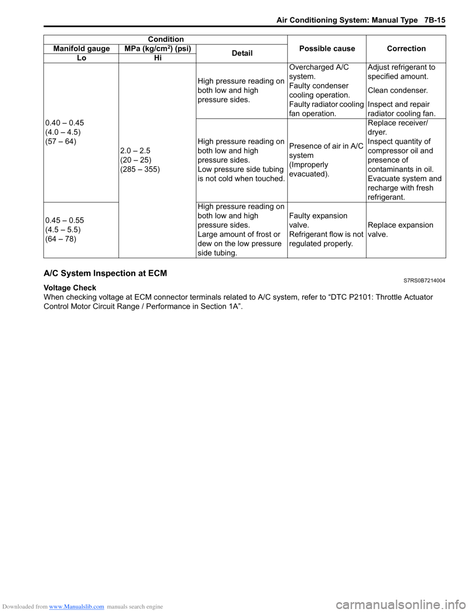
0.40 – 0.45
(4.0 – 4.5)
(57 – 64)
2.0 – 2.5
(20 – 25)
(285 – 355) High pressure reading on
both low and high
pressure sides.
Overcharged A/C
system.
Adjust refrigerant to
specified amount.
Faulty condenser
cooling operation. Clean condenser.
Faulty radiator cooling
fan operation. Inspect and repair
radiator cooling fan.
High pressure reading on
both low and high
pressure sides.
Low pressure side tubing
is not cold when touched. Presence of air in A/C
system
(Improperly
evacuated).Replace receiver/
dryer.
Inspect quantity of
compressor oil and
presence of
contaminants in oil.
Evacuate system and
recharge with fresh
refrigerant.
0.45 – 0.55
(4.5 – 5.5)
(64 – 78) High pressure reading on
both low and high
pressure sides.
Large amount of frost or
dew on the low pressure
side tubing.Faulty expansion
valve.
Refrigerant flow is not
regulated properly.
Replace expansion
valve.
Condition
Possible cause Correction
Manifold gauge MPa (kg/cm
2) (psi)
Detail
Lo Hi
Page 985 of 1496
Downloaded from www.Manualslib.com manuals search engine Air Conditioning System: Automatic Type 7B-37
On-Board Diagnostic System DescriptionS7RS0B7221007
NOTE
The diagnostic information as diagnostic
trouble code (DTC) can be known by using
SUZUKI scan tool. For further details, refer to
“DTC Check”.
HVAC control module detect s malfunctions, which may
occur in the following area.
• Outside air temperature sensor
• Inside air temperature sensor
• Evaporator temperature sensor
• Sunload sensor
• ECT sensor
• Temperature control actuator of HVAC unit
• Air flow control actuator of HVAC unit
• A/C refrigerant pressure sensor • HVAC control module
• VSS
• Serial Communication line
• CAN communication line
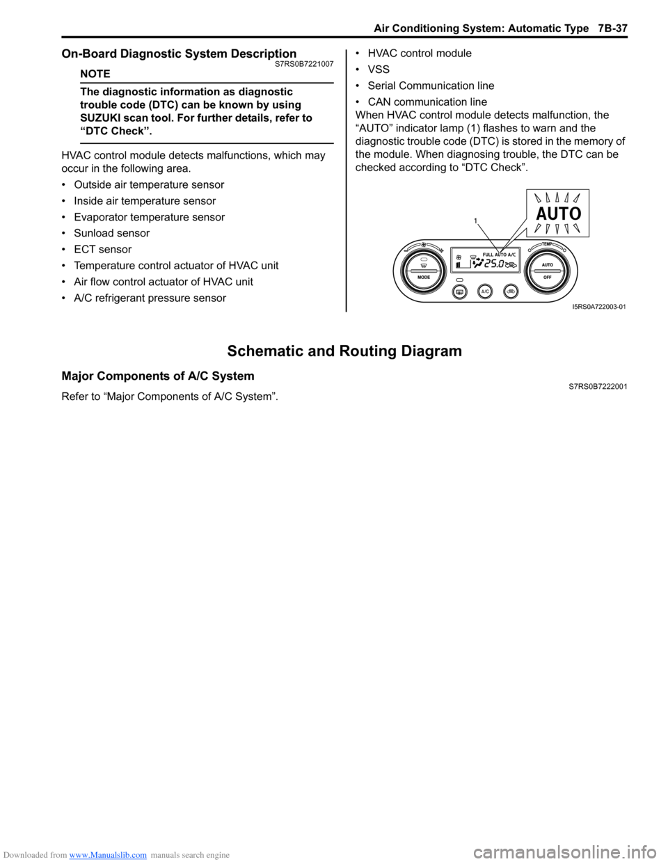
When HVAC control module detects malfunction, the
“AUTO” indicator lamp (1) flashes to warn and the
diagnostic trouble code (DTC) is stored in the memory of
the module. When diagnosing trouble, the DTC can be
checked according to “DTC Check”.
Schematic and Routing Diagram
Major Components of A/C SystemS7RS0B7222001
Refer to “Major Components of A/C System”.
1
I5RS0A722003-01
Page 994 of 1496
Downloaded from www.Manualslib.com manuals search engine 7B-46 Air Conditioning System: Automatic Type
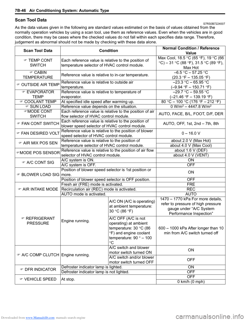
Scan Tool DataS7RS0B7224007
As the data values given in the following are standard values estimated on the basis of values obtained from the
normally operation vehicles by using a scan tool, use them as reference values. Even when the vehicles are in good
condition, there may be cases where the checked values do not fall within each specifies data range. Therefore,
judgement as abnormal should not be ma de by checking with these data alone.
Scan Tool Data Condition Normal Condition / Reference
Va l u e
�) TEMP CONT
SWITCH Each reference value is relative to the position of
temperature selector of HVAC control module. Max Cool, 18.5
°C (65 ° F), 19 °C (66
° C) – 31 °C (88 °F), 31.5 °C (89 °F),
Max Hot
�) CABIN
TEMPERATURE Reference value is relative to in-car temperature. –6.5
°C – 57.25 ° C
(20.3 °F – 135.05 °F)
�) OUTSIDE AIR TEMP Reference value is relative to outside air
temperature. –23.3
°C – 65.95 °C
(–9.94 °F – 150.71 °F)
�) EVAPORATOR
TEMP Reference value is relative to temperature of
evaporator. –29.7
°C – 59.55 °C
(–21.46 °F – 139.19 °F)
�) COOLANT TEMP At specified id le speed after warming up. 80 °C – 100 °C (176 ° F – 212 ° F)
�) SUN LOAD Reference value depends on the situation. 0 W/m
2 – 4447.8 W/m2
�)MODE CONT
SWITCH Each reference value is relative to the position of air
flow selector of HVAC control module.
AUTO, FACE, B/L, FOOT, D/F, DER
�) FAN CONT SWITCH Each reference value is relative to the position of
blower speed selector of HVAC control module. AUTO, OFF, 1st, 2nd – 7th, 8th
�) FAN DESIRED VOLT Reference value is relative to the position of blower
speed selector of HVAC control module. 0 – 16.0 V
�) AIR MIX POS SEN Reference value is relative to the position of
temperature selector of HVAC control module. about 2.0 V (Max Hot)
about 4.0 V (Max Cool)
�) MODE POS SENSOR Reference value is relative to the position of air flow
selector of HVAC control module. about 1.6 V (DEF)
about 4.0 V (VENT)
�) A/C CONT SIG A/C system is ON. ON
A/C system is OFF. OFF
�) BLOWER LOAD SIG Position of blower speed selector is 1st position or
more.
ON
Position of blower speed selector is OFF position. OFF
�) AIR INTAKE MODE Fresh air (FRE) mode is activated. FRE
Recirculation air (REC) mode is activated. REC
AUTO mode is activated. AUTO
�) REFRIGERANT
PRESSURE Engine running. A/C ON (A/C is operating)
at ambient temperature:
30
°C (86 °F) 1470 – 1770 kPa For more details,
refer to pressure of high pressure
gauge under “A/C System Performance Inspection”
A/C OFF (A/C is not
operating) at ambient
temperature: 30 °C (86
° F) and engine coolant
temperature: 90 ° – 100
° C 600 – 1000 kPa After longer than 10
min from A/C switch turned off
�) A/C COMP CLUTCH Engine running. A/C switch and blower
motor switch turned ON
ON
A/C switch and/or blower
motor switch turned OFF OFF
�) DFR INDICATOR Defroster indicator
lamp is lighted. ON
Defroster indicator la mp is not lighted. OFF
�) VEHICLE SPEED At stop. OFF
0 km/h (0 mph)
Page 996 of 1496
Downloaded from www.Manualslib.com manuals search engine 7B-48 Air Conditioning System: Automatic Type
Description for Each Step
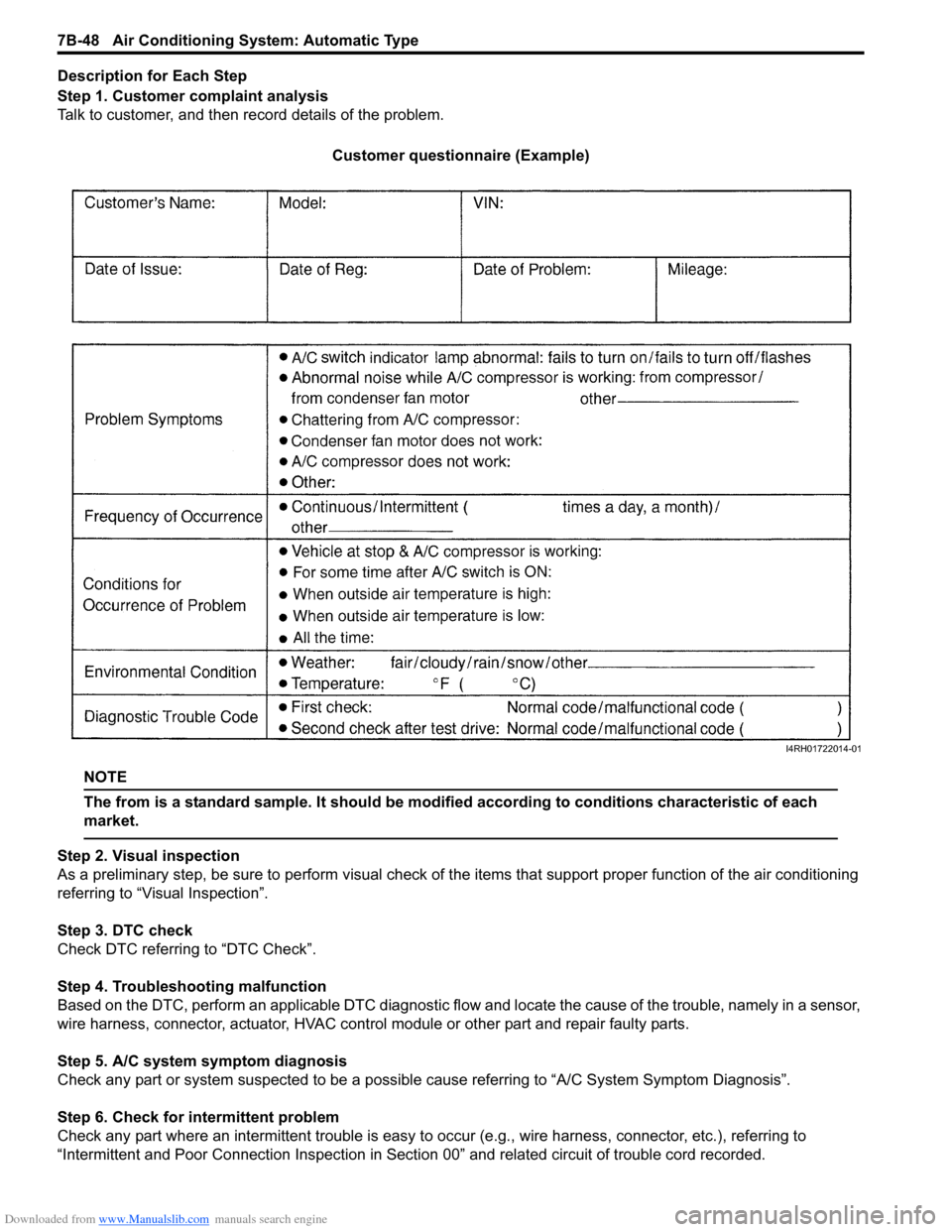
Step 1. Customer complaint analysis
Talk to customer, and then record details of the problem.
Customer questionnaire (Example)
NOTE
The from is a standard sample. It should be modified according to conditions characteristic of each
market.
Step 2. Visual inspection
As a preliminary step, be sure to perform visual check of th e items that support proper function of the air conditioning
referring to “Visual Inspection”.
Step 3. DTC check
Check DTC referring to “DTC Check”.
Step 4. Troubleshooting malfunction
Based on the DTC, perform an applicable DTC diagnostic flow and locate the cause of the trouble, namely in a sensor,
wire harness, connector, actuat or, HVAC control module or other part and repair faulty parts.
Step 5. A/C system symptom diagnosis
Check any part or system suspected to be a possible cause referring to “A/C System Symptom Diagnosis”.
Step 6. Check for intermittent problem
Check any part where an intermittent trouble is easy to oc cur (e.g., wire harness, connector, etc.), referring to
“Intermittent and Poor Connection Inspection in Sect ion 00” and related circuit of trouble cord recorded.
I4RH01722014-01
Page 1050 of 1496
Downloaded from www.Manualslib.com manuals search engine 8B-12 Air Bag System:
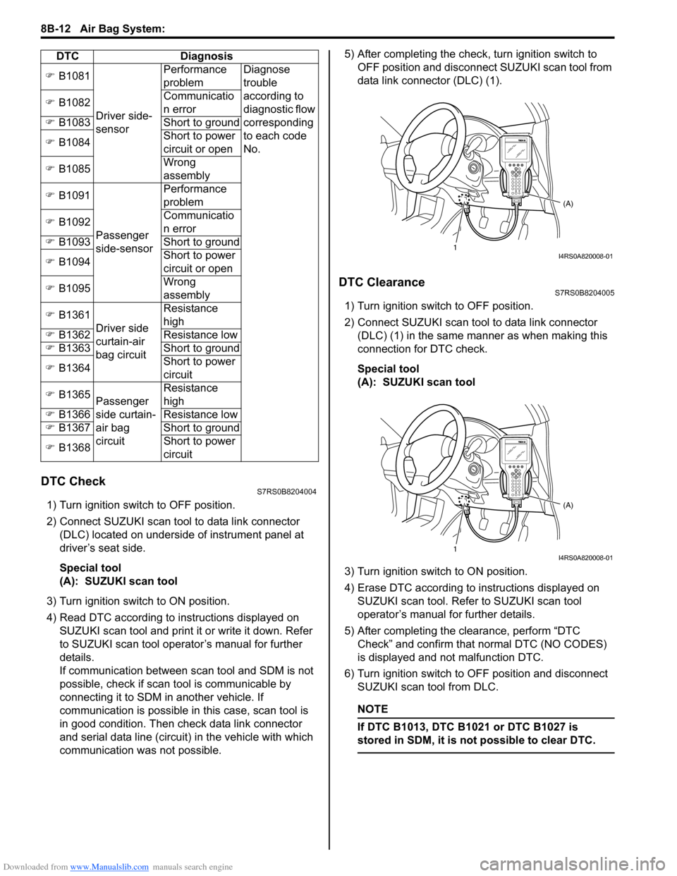
DTC CheckS7RS0B8204004
1) Turn ignition switch to OFF position.
2) Connect SUZUKI scan tool to data link connector (DLC) located on underside of instrument panel at
driver’s seat side.
Special tool
(A): SUZUKI scan tool
3) Turn ignition switch to ON position.
4) Read DTC according to instructions displayed on SUZUKI scan tool and print it or write it down. Refer
to SUZUKI scan tool operator’s manual for further
details.
If communication between scan tool and SDM is not
possible, check if scan tool is communicable by
connecting it to SDM in another vehicle. If
communication is possible in this case, scan tool is
in good condition. Then check data link connector
and serial data line (circuit) in the vehicle with which
communication was not possible. 5) After completing the check,
turn ignition switch to
OFF position and disconnect SUZUKI scan tool from
data link connector (DLC) (1).
DTC ClearanceS7RS0B8204005
1) Turn ignition switch to OFF position.
2) Connect SUZUKI scan tool to data link connector (DLC) (1) in the same manner as when making this
connection for DTC check.
Special tool
(A): SUZUKI scan tool
3) Turn ignition switch to ON position.
4) Erase DTC according to instructions displayed on
SUZUKI scan tool. Refer to SUZUKI scan tool
operator’s manual for further details.
5) After completing the clearance, perform “DTC Check” and confirm that normal DTC (NO CODES)
is displayed and not malfunction DTC.
6) Turn ignition switch to OFF position and disconnect SUZUKI scan tool from DLC.
NOTE
If DTC B1013, DTC B1 021 or DTC B1027 is
stored in SDM, it is not possible to clear DTC.
�) B1081
Driver side-
sensor Performance
problem
Diagnose
trouble
according to
diagnostic flow
corresponding
to each code
No.
�)
B1082 Communicatio
n error
�) B1083 Short to ground
�) B1084 Short to power
circuit or open
�) B1085 Wrong
assembly
�) B1091
Passenger
side-sensor Performance
problem
�) B1092 Communicatio
n error
�) B1093 Short to ground
�) B1094 Short to power
circuit or open
�) B1095 Wrong
assembly
�) B1361
Driver side
curtain-air
bag circuit Resistance
high
�) B1362 Resistance low
�) B1363 Short to ground
�) B1364 Short to power
circuit
�) B1365
Passenger
side curtain-
air bag
circuit Resistance
high
�) B1366 Resistance low
�) B1367 Short to ground
�) B1368 Short to power
circuit
DTC Diagnosis
1
(A)I4RS0A820008-01
1(A)I4RS0A820008-01