2008 SUZUKI SWIFT tail
[x] Cancel search: tailPage 370 of 1496
Downloaded from www.Manualslib.com manuals search engine 1F-7 Engine Cooling System:
Cooling System Flush and RefillS7RS0B1606005
WARNING!
To help avoid danger of being burned, do not
remove radiator cap while engine and
radiator are still hot. Scalding fluid and steam
can be blown out under pressure if cap is
taken off too soon.
NOTE
For detail of coolant specification, refer to
“Coolant Description”.
1) Remove radiator cap when engine is cool as follows.a) Turn cap counterclockwise slowly until it reaches a “stop” (Do not press down while turning it).
b) Wait until pressure is relieved (indicated by a hissing sound) then press down on cap and
continue to turn it counterclockwise.
2) With radiator cap removed, run engine until upper radiator hose is hot (this shows that thermostat is
open and coolant is flowing through system).
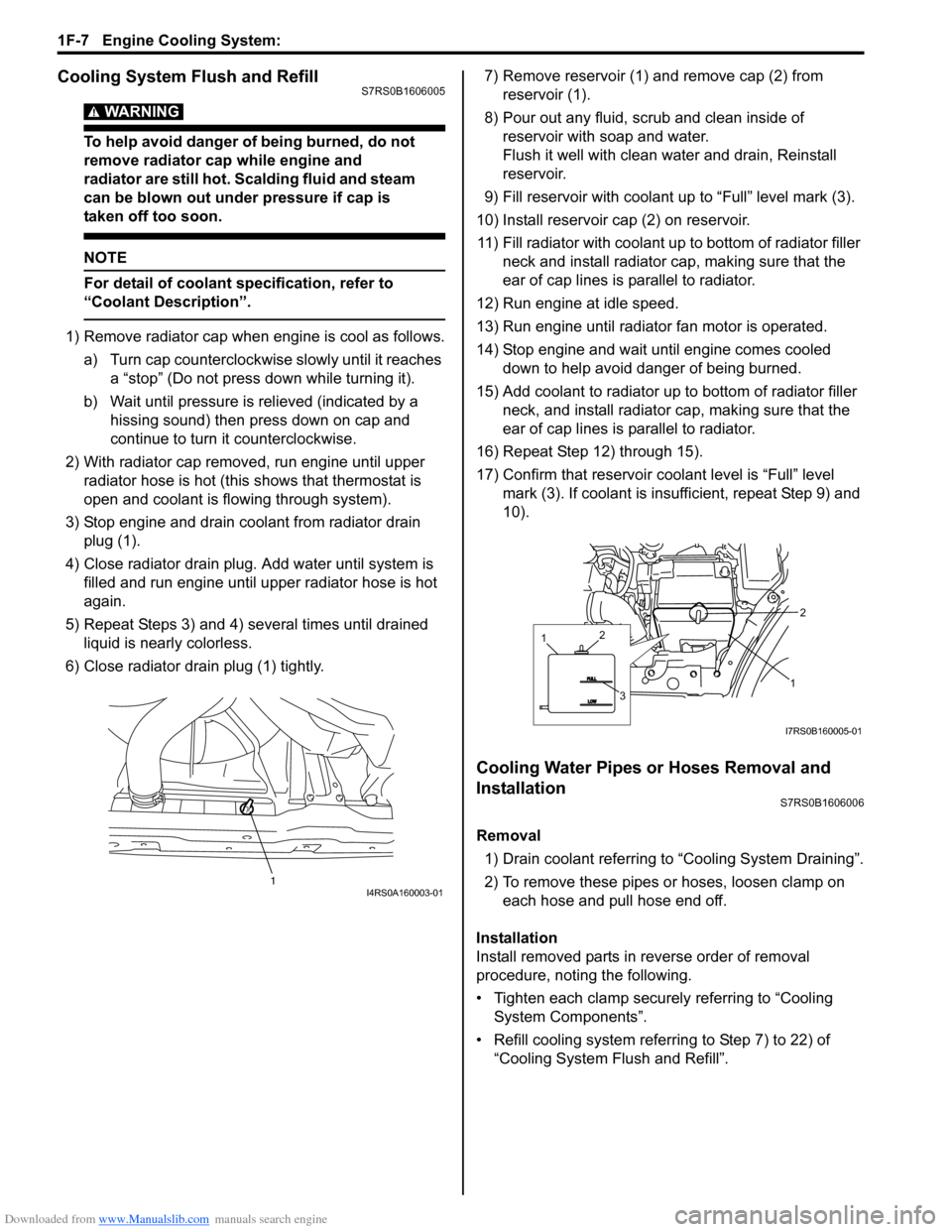
3) Stop engine and drain coolant from radiator drain plug (1).
4) Close radiator drain plug. Add water until system is filled and run engine until up per radiator hose is hot
again.
5) Repeat Steps 3) and 4) several times until drained liquid is nearly colorless.
6) Close radiator drain plug (1) tightly. 7) Remove reservoir (1) and remove cap (2) from
reservoir (1).
8) Pour out any fluid, scrub and clean inside of reservoir with soap and water.
Flush it well with clean water and drain, Reinstall
reservoir.
9) Fill reservoir with coolant up to “Full” level mark (3).
10) Install reservoir cap (2) on reservoir. 11) Fill radiator with coolant up to bottom of radiator filler neck and install radiator cap, making sure that the
ear of cap lines is parallel to radiator.
12) Run engine at idle speed.
13) Run engine until radiator fan motor is operated.
14) Stop engine and wait until engine comes cooled down to help avoid danger of being burned.
15) Add coolant to radiator up to bottom of radiator filler
neck, and install radiator ca p, making sure that the
ear of cap lines is parallel to radiator.
16) Repeat Step 12) through 15).
17) Confirm that reservoir cool ant level is “Full” level
mark (3). If coolant is insu fficient, repeat Step 9) and
10).
Cooling Water Pipes or Hoses Removal and
Installation
S7RS0B1606006
Removal
1) Drain coolant referring to “Cooling System Draining”.
2) To remove these pipes or hoses, loosen clamp on each hose and pull hose end off.
Installation
Install removed parts in reverse order of removal
procedure, noting the following.
• Tighten each clamp securely referring to “Cooling System Components”.
• Refill cooling system referrin g to Step 7) to 22) of
“Cooling System Flush and Refill”.
1I4RS0A160003-01
1
2
1
3
2
I7RS0B160005-01
Page 376 of 1496
Downloaded from www.Manualslib.com manuals search engine 1G-1 Fuel System:
Engine
Fuel System
Precautions
Precautions on Fuel System ServiceS7RS0B1700001
WARNING!
Before attempting service of any type on fuel system, the following should be always observed in
order to reduce the risk of fire and personal injury.
• Disconnect negative cable at battery.
• Do not smoke, and place no smoking signs near work area.
• Be sure to have CO
2 fire extinguisher handy.
• Be sure to perform work in a well-ventilated area and away from any open flames (such as gas hot heater).
• Wear safety glasses.
• To relieve fuel vapor pressure in fuel tank, remove fuel filler cap from fuel filler neck and then
reinstall it.
• As fuel feed line is still under high fuel pr essure even after stopping engine, loosening or
disconnecting fuel feed line directly may cause dangerous spout of fuel. Before loosening or
disconnecting fuel feed line, make sure to relieve fuel pressure referring to “Fuel Pressure Relief
Procedure”.
• A small amount of fuel may be released when the fuel line is disconnected. In order to reduce the risk of personal injury, cover a shop cloth to the fitting to be disconnected. Be sure to put that cloth
in an approved container after disconnecting.
• Never run engine with fuel pump relay disconnected when engine and exhaust system are hot.
• Note that fuel hose connection varies with each type of pipe. Be sure to connect and clamp each hose correctly referring to “Fuel Hose Disconnecting and Reconnecting”.
After connecting, make sure that it has no twist or kink.
• When installing inje ctor or fuel feed pipe, lubr icate its O-ring with gasoline.
General Description
Fuel System DescriptionS7RS0B1701001
CAUTION!
This engine requires the unleaded fuel only.
The leaded and/or low lead fuel can result in
engine damage and reduce the effectiveness
of the emission control system.
The main components of the fuel system are fuel tank,
fuel pump assembly (with fuel filter, fuel level gauge, fuel
pressure regulator, fuel feed line and fuel vapor line.
For the details of fuel flow, refer to “Fuel Delivery System
Diagram”.
Fuel Delivery System DescriptionS7RS0B1701002
The fuel delivery system consists of the fuel tank, fuel
pump assembly (with built-in f uel filter and fuel pressure
regulator), delivery pipe, injectors and fuel feed line.
The fuel in the fuel tank is pumped up by the fuel pump,
sent into delivery pipe and injected by the injectors.
As the fuel pump assembly is equipped with built-in fuel
filter and fuel pressure regulator, the fuel is filtered and
its pressure is regulated before being sent to the feed
pipe.
The excess fuel at fuel pressure regulation process is
returned back into the fuel tank.
Also, fuel vapor generated in fuel tank is led through the
fuel vapor line into the EVAP canister.
For system diagram, refer to “Fuel Delivery System
Diagram”.
Page 425 of 1496
Downloaded from www.Manualslib.com manuals search engine Exhaust System: 1K-2
Repair Instructions
Exhaust System ComponentsS7RS0B1B06001
WARNING!
To avoid the danger of being burned, do not touch the exhaust system when the system is hot. Any
service on the exhaust system should be performed when the system is cool.
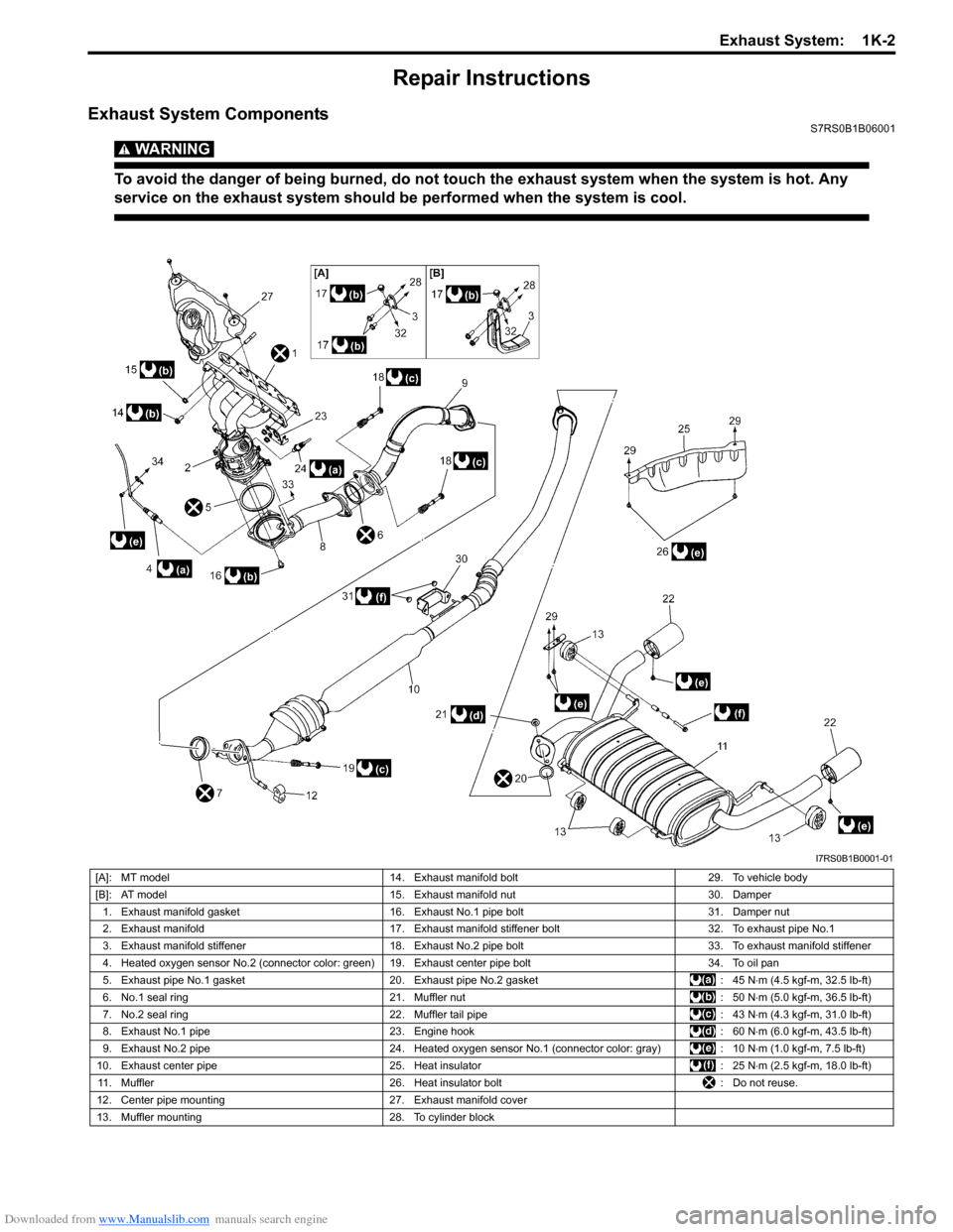
I7RS0B1B0001-01
[A]: MT model14. Exhaust manifold bolt 29. To vehicle body
[B]: AT model 15. Exhaust manifold nut 30. Damper
1. Exhaust manifold gasket 16. Exhaust No.1 pipe bolt 31. Damper nut
2. Exhaust manifold 17. Exhaust manifold stiffener bolt 32. To exhaust pipe No.1
3. Exhaust manifold stiffener 18. Exhaust No.2 pipe bolt 33. To exhaust manifold stiffener
4. Heated oxygen sensor No.2 (connector color: green) 19. Exhaust center pipe bolt 34. To oil pan
5. Exhaust pipe No.1 gasket 20. Exhaust pipe No.2 gasket : 45 N⋅m (4.5 kgf-m, 32.5 lb-ft)
6. No.1 seal ring 21. Muffler nut : 50 N⋅m (5.0 kgf-m, 36.5 lb-ft)
7. No.2 seal ring 22. Muffler tail pipe : 43 N⋅m (4.3 kgf-m, 31.0 lb-ft)
8. Exhaust No.1 pipe 23. Engine hook : 60 N⋅m (6.0 kgf-m, 43.5 lb-ft)
9. Exhaust No.2 pipe 24. Heated oxygen sensor No.1 (connector color: gray) : 10 N⋅m (1.0 kgf-m, 7.5 lb-ft)
10. Exhaust center pipe 25. Heat insulator : 25 N⋅m (2.5 kgf-m, 18.0 lb-ft)
11. Muffler 26. Heat insulator bolt : Do not reuse.
12. Center pipe mounting 27. Exhaust manifold cover
13. Muffler mounting 28. To cylinder block
Page 456 of 1496

Downloaded from www.Manualslib.com manuals search engine 2C-2 Rear Suspension:
Repair Instructions
Rear Wheel Alignment InspectionS7RS0B2306017
Measure toe and camber referring to “Front Wheel
Alignment Inspection and Adjustment in Section 2B”.
NOTE
Rear suspension is not adjustable structure.
Rear toe (total)
: IN 3.8 ± 3.8 mm (IN 0.1969 ± 0.1969 in)
Rear camber
: –1 ° ± 1
If measured value is out of specified value, check
following items for damage, deformation and crack.
• Rear axle (torsion beam)
• Spindle, wheel hub or wheel bearing
• Vehicle body
Rear Shock Absorber Removal and InstallationS7RS0B2306001
Removal 1) Hoist vehicle and remove rear wheels.
2) Remove tail end member trim (1) and quarter inner trim (2).
3) Support rear axle by using floor jack to prevent it from lowering.
4) Remove shock absorber lower nut.
5) Remove shock absorber upper nut. Then remove shock absorber, a pair of upper washers and lower
washer. Installation
1) Install shock absorber (1), a pair of upper washers (2) and lower washer.
Tighten new rear shock absorber upper nut (4) and
lower nut temporarily at this step.
CAUTION!
Never reuse the removed rear shock
absorber upper nut.
NOTE
A pair of upper washers (2) are installed as
shown in figure.
3. Clip
3
3 2
3
1
3
I7RS0B230001-01
3. Body panel
14
3 2
I6RS0C230005-01
Page 457 of 1496
Downloaded from www.Manualslib.com manuals search engine Rear Suspension: 2C-3
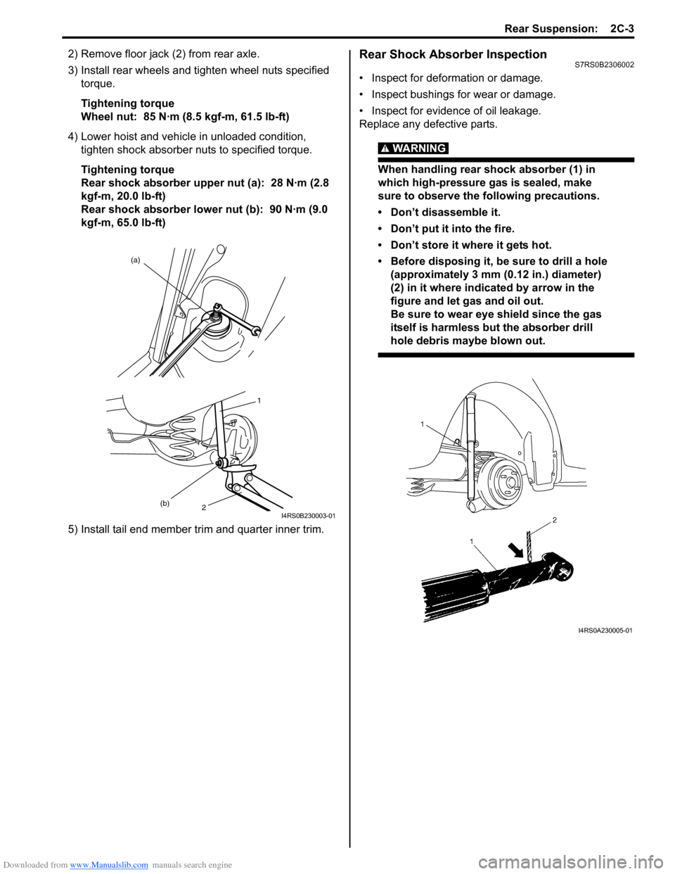
2) Remove floor jack (2) from rear axle.
3) Install rear wheels and tighten wheel nuts specified torque.
Tightening torque
Wheel nut: 85 N·m (8.5 kgf-m, 61.5 lb-ft)
4) Lower hoist and vehicle in unloaded condition, tighten shock absorber nuts to specified torque.
Tightening torque
Rear shock absorber upper nut (a): 28 N·m (2.8
kgf-m, 20.0 lb-ft)
Rear shock absorber lower nut (b): 90 N·m (9.0
kgf-m, 65.0 lb-ft)
5) Install tail end member trim and quarter inner trim.Rear Shock Absorber InspectionS7RS0B2306002
• Inspect for deformation or damage.
• Inspect bushings for wear or damage.
• Inspect for evidence of oil leakage.
Replace any defective parts.
WARNING!
When handling rear shock absorber (1) in
which high-pressure gas is sealed, make
sure to observe the following precautions.
• Don’t disassemble it.
• Don’t put it into the fire.
• Don’t store it where it gets hot.
• Before disposing it, be sure to drill a hole (approximately 3 mm (0.12 in.) diameter)
(2) in it where indicated by arrow in the
figure and let gas and oil out.
Be sure to wear eye shield since the gas
itself is harmless but the absorber drill
hole debris maybe blown out.
(a)
1
(b) 2
I4RS0B230003-01
I4RS0A230005-01
Page 461 of 1496
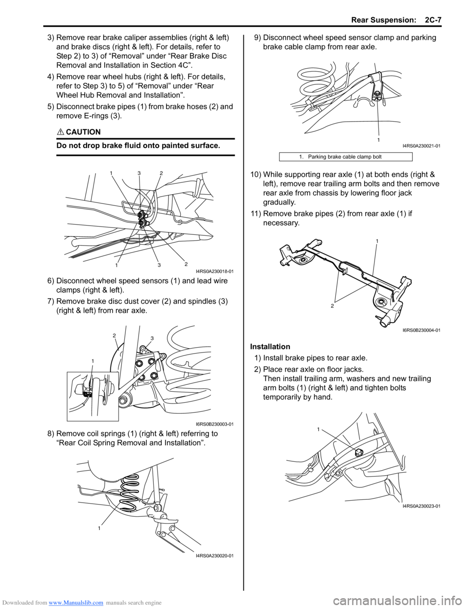
Downloaded from www.Manualslib.com manuals search engine Rear Suspension: 2C-7
3) Remove rear brake caliper assemblies (right & left)
and brake discs (right & left ). For details, refer to
Step 2) to 3) of “Removal” under “Rear Brake Disc
Removal and Installa tion in Section 4C”.
4) Remove rear wheel hubs (r ight & left). For details,
refer to Step 3) to 5) of “Removal” under “Rear
Wheel Hub Removal and Installation”.
5) Disconnect brake pipes (1) from brake hoses (2) and remove E-rings (3).
CAUTION!
Do not drop brake fluid onto painted surface.
6) Disconnect wheel speed sensors (1) and lead wire clamps (right & left).
7) Remove brake disc dust cover (2) and spindles (3) (right & left) from rear axle.
8) Remove coil springs (1) (right & left) referring to “Rear Coil Spring Removal and Installation”. 9) Disconnect wheel speed sensor clamp and parking
brake cable clamp from rear axle.
10) While supporting rear axle (1) at both ends (right & left), remove rear trailing arm bolts and then remove
rear axle from chassis by lowering floor jack
gradually.
11) Remove brake pipes (2) from rear axle (1) if necessary.
Installation 1) Install brake pipes to rear axle.
2) Place rear axle on floor jacks. Then install trailing arm, washers and new trailing
arm bolts (1) (right & left) and tighten bolts
temporarily by hand.
1
1
2
2
3
3I4RS0A230018-01
1
2
3
I6RS0B230003-01
1
I4RS0A230020-01
1. Parking brake cable clamp bolt
1I4RS0A230021-01
2
1
I6RS0B230004-01
1
I4RS0A230023-01
Page 466 of 1496

Downloaded from www.Manualslib.com manuals search engine 2C-12 Rear Suspension:
• Check noise and smooth rotation of wheel by rotating wheel. If it is defect ive, replace bearing.
Spindle Removal and InstallationS7RS0B2306014
Removal
1) Remove rear brake caliper assembly and brake disc. For details, refer to Step 2) to 4) of “Removal” under
“Rear Brake Disc Removal and Installation in
Section 4C”.
2) Remove rear wheel hub. For details, refer to Step 3) to 5) of “Removal” under “Rear Wheel Hub Removal
and Installation”.
3) Disconnect wheel speed sensor (1).
4) Remove brake disc dust cover (2) and spindle (3) from rear axle. Installation
1) Install brake disc dust cover (1), spindle (2) and new spindle bolts (3) and then tighten spindle bolts to
specified torque.
CAUTION!
Never reuse the removed rear spindle bolts.
Bolts are pre-coated wi th friction stabilizer.
Be sure to replace pre-coated bolt with a new
one, or bolt may loosen.
Tightening torque
Rear spindle bolt (a): 88 N·m (8.8 kgf-m, 64.0 lb-
ft)
2) Connect wheel speed sensor (4) and tighten wheel speed sensor bolt to specified torque.
Tightening torque
Wheel speed sensor bolt (b): 11 N·m (1.1 kgf-m,
8.0 lb-ft)
3) Install rear wheel hub re ferring to “Rear Wheel Hub
Removal and Installation”.
4) Install brake disc and rear brake caliper assembly referring to “Rear Brake Disc Removal and
Installation in Section 4C”.
5) Install wheel and tighten wheel nuts to specified torque.
Tightening torque
Wheel nut: 85 N·m (8.5 kgf-m, 61.5 lb-ft)
6) Adjust parking brake cable. For adjustment, see “Parking Brake Inspection and Adjustment in Section
4D”.
7) Perform brake test (foot brake and parking brake).
8) Check each installed part for fluid leakage.
I3RM0A230050-01
2
1 3
I6RS0B230015-01
1
(b)
4
2
3, (a)
I6RS0B230016-01
Page 475 of 1496

Downloaded from www.Manualslib.com manuals search engine Wheels and Tires: 2D-8
Tire Mounting and DismountingS7RS0B2406004
CAUTION!
When installing tire which has arrow
indicating tire rotation direction to wheel,
make sure that this tire rotation direction is
same as actual tire rotation direction when
vehicle is moving forward. Otherwise, it is
not possible to install wheel with tire to
vehicle in specified direction.
Use a tire changing machine to mount or dismount tires.
Follow equipment manufacturer’s instructions. Do not
use hand tools or tire irons al one to change tires as they
may damage tire beads or wheel rim.
Rim bead seats should be cleaned with a wire brush or
coarse steel wool to remove lubricants, old rubber and
light rust. Before mounting or dismounting a tire, bead
area should be well lubricated with approved tire
lubricant.
After mounting, inflate to specified pressure shown on
tire placard so that beads are completely seated.
WARNING!
Do not stand over tire when inflating. Bead
may break when bead snaps over rim’s safety
hump and cause serious personal injury.
Do not exceed 330 kpa (47.9 psi) pressure
when inflating. If 330 kpa (47.9 psi) pressure
will not seat beads, deflate, re-lubricate and
reinflate.
Over inflation may cause bead to break and
cause serious personal injury.
Install valve core and inflate to proper pressure.
Tire RepairS7RS0B2406005
There are many different materials and techniques on
the market to repair tires. As not all of these work on all
types of tires, tire manufacturers have published detailed
instructions on how and when to repair tires. These
instructions can be obtained from each tire
manufacturer.
Tire Repair for Emergency Repaired-Tire with
Sealant
S7RS0B2406006
WARNING!
Be sure to observe “Precaution for
Emergency Flat Tire Repair Kit”. Otherwise,
your health may be ruined.
1) Remove flat tire repair sealant from tire using plug (1), filler hose (2), sealant bottle (3) and extension
hose (4) in kit as follows.
a) Remove plug from fille r hose of sealant bottle.
Then connect ext ension hose to tip of filler hose.
b) Remove tire containing flat tire repair sealant from vehicle.
c) Loosen valve core carefully to release air.
WARNING!
Take care not to make sealant blast out from
valve. Otherwise, your health may be ruined.
d) Remove tire bead inside rim of wheel.
e) Make a clearance by inserting a tire lever (2) between tire bead and rim, and then insert hose
(1) thought clearance as shown in figure.
f) Press the bottle and suck out sealant (4), using bottle (3) as a pump.
NOTE
To make sealant easy to suck up from tire,
set bottle lower than sealant surface.
g) Change hose end position and repeat above step f) until sealant is not sucked out.
h) Put cap on bottle so that collected sealant does not leak.
4
1
2
3
I6RS0B240004-01
1 4
3 2
I6RS0C240003-01