2008 SUZUKI SWIFT intermittent
[x] Cancel search: intermittentPage 5 of 1496
Downloaded from www.Manualslib.com manuals search engine Table of Contents 00- i
00
Section 00
CONTENTS
Precautions
Precautions ............................................... 00-1
Precautions........................................................... 00-1
Precautions for Vehicles Equipped with a Supplemental Restraint (A ir Bag) System ........ 00-1
General Precautions ........... ................................ 00-4
Warning for Wheel (with tire) Removal ............... 00-7
Warning for Handling Emergency Flat Tire Repair Kit .......................................................... 00-7
Precautions for Catalytic Converter .................... 00-7
Precautions for Installing Mobile Communication Equipment ............................... 00-7
Precaution for CAN Communication System ...... 00-7 Precautions for Electrical Circuit Service ............ 00-8
Air Bag Warning ................................................ 00-10
Air Bag System Service Warning ...................... 00-10
Fastener Caution............................................... 00-10
Suspension Caution .......................................... 00-10
Wheels and Tires Caution ................................. 00-10
Precaution for Vehicle Equipped with ESP
®
System ............................................................ 00-11
Brake Caution ................................................... 00-11
Repair Instructions ........ .................................... 00-11
Electrical Circuit Inspection Procedure ............. 00-11
Intermittent and Poor Co nnection Inspection .... 00-13
Page 18 of 1496
Downloaded from www.Manualslib.com manuals search engine 00-13 Precautions:
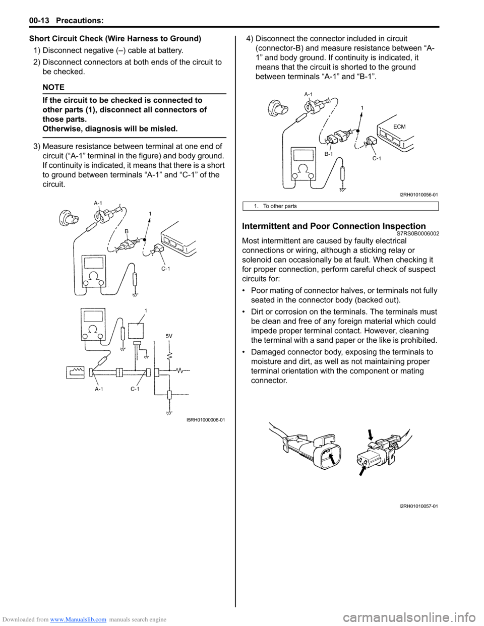
Short Circuit Check (Wire Harness to Ground)1) Disconnect negative (–) cable at battery.
2) Disconnect connectors at bot h ends of the circuit to
be checked.
NOTE
If the circuit to be checked is connected to
other parts (1), disconnect all connectors of
those parts.
Otherwise, diagnosis will be misled.
3) Measure resistance between terminal at one end of circuit (“A-1” terminal in the figure) and body ground.
If continuity is indicated, it means that there is a short
to ground between terminals “A-1” and “C-1” of the
circuit. 4) Disconnect the connector included in circuit
(connector-B) and measure resistance between “A-
1” and body ground. If continuity is indicated, it
means that the circuit is shorted to the ground
between terminals “A-1” and “B-1”.
Intermittent and Poor Connection InspectionS7RS0B0006002
Most intermittent are caused by faulty electrical
connections or wiring, although a sticking relay or
solenoid can occasionally be at fault. When checking it
for proper connection, perfor m careful check of suspect
circuits for:
• Poor mating of connector halves, or terminals not fully seated in the connector body (backed out).
• Dirt or corrosion on the terminals. The terminals must be clean and free of any foreign material which could
impede proper terminal contact. However, cleaning
the terminal with a sand paper or the like is prohibited.
• Damaged connector body, exposing the terminals to moisture and dirt, as well as not maintaining proper
terminal orientation with the component or mating
connector.
I5RH01000006-01
1. To other parts
I2RH01010056-01
I2RH01010057-01
Page 19 of 1496
Downloaded from www.Manualslib.com manuals search engine Precautions: 00-14
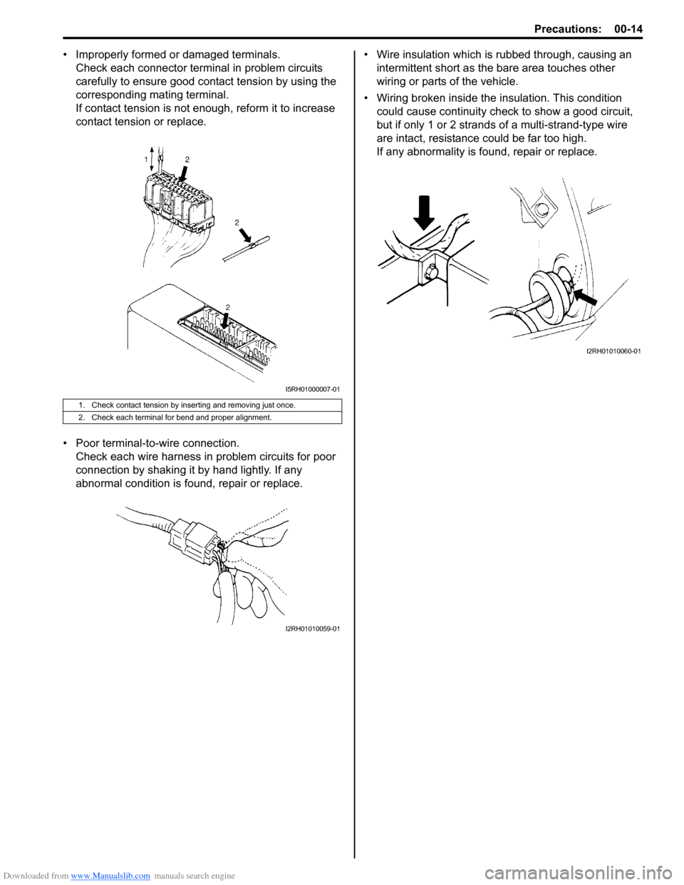
• Improperly formed or damaged terminals.Check each connector terminal in problem circuits
carefully to ensure good contact tension by using the
corresponding mating terminal.
If contact tension is not enough, reform it to increase
contact tension or replace.
• Poor terminal-to -wire connection.
Check each wire harness in problem circuits for poor
connection by shaking it by hand lightly. If any
abnormal condition is found, repair or replace. • Wire insulation which is rubbed through, causing an
intermittent short as the bare area touches other
wiring or parts of the vehicle.
• Wiring broken inside the insulation. This condition
could cause continuity check to show a good circuit,
but if only 1 or 2 strands of a multi-strand-type wire
are intact, resistance could be far too high.
If any abnormality is found, repair or replace.
1. Check contact tension by inserting and removing just once.
2. Check each terminal for bend and proper alignment.
I5RH01000007-01
I2RH01010059-01
I2RH01010060-01
Page 72 of 1496

Downloaded from www.Manualslib.com manuals search engine 1A-22 Engine General Information and Diagnosis:
Diagnostic Information and Procedures
Engine and Emission Control System CheckS7RS0B1104001
Refer to the following items for the details of each step.Step Action Yes No 1 �) Customer complaint analysis
1) Perform customer complaint analysis referring to “Customer Complaint Analysis”.
Was customer complaint analysis performed? Go to Step 2. Perform customer
complaint analysis.
2 �) DTC / Freeze frame data check, record and clearance
1) Check for DTC (including pending DTC) referring to “DTC / Freeze Frame Data Check, Record and
Clearance”.
Is there any DTC(s)? Print DTC and freeze
frame data or write them
down and clear them by
referring to “DTC
Clearance”, and go to
St ep 3 .Go to Step 4.
3 �) Visual inspection
1) Perform visual inspection referring to “Visual Inspection”.
Is there any faulty condition? Repair or replace
malfunction part, and go
to Step 11.
Go to Step 5.
4 �) Visual inspection
1) Perform visual inspection referring to “Visual Inspection”.
Is there any faulty condition? Repair or replace
malfunction part, and go
to Step 11.
Go to Step 8.
5 �) Trouble symptom confirmation
1) Confirm trouble symptom referring to “Trouble Symptom Confirmation”.
Is trouble symptom identified? Go to Step 6.
Go to Step 7.
6 �) Rechecking and record of DTC / Freeze frame data
1) Recheck for DTC and freeze frame data referring to “DTC Check”.
Is there any DTC(s)? Go to Step 9.
Go to Step 8.
7 �) Rechecking and record of DTC / Freeze frame data
1) Recheck for DTC and freeze frame data referring to “DTC Check”.
Is there any DTC(s)? Go to Step 9.
Go to Step 10.
8 �) Engine basic inspection and engine symptom
diagnosis
1) Check and repair according to “Engine Basic Inspection”
and “Engine Symptom Diagnosis”.
Are check and repair complete? Go to Step 11. Check and repair
malfunction part(s), and
go to Step 11.
9 �) Troubleshooting for DTC
1) Check and repair according to applicable DTC diag. flow.
Are check and repair complete? Go to Step 11. Check and repair
malfunction part(s), and
go to Step 11.
10 �) Intermittent problems check
1) Check for intermittent problems referring to “Intermittent Problems Check”.
Is there any faulty condition? Repair or replace
malfunction part(s), and
go to Step 11.
Go to Step 11.
Page 75 of 1496
Downloaded from www.Manualslib.com manuals search engine Engine General Information and Diagnosis: 1A-25
Step 2: DTC / Freeze Frame Data Check, Record and
Clearance
First, check DTC (including pending DTC), referring to
“DTC Check”. If DTC is indicated, print it and freeze
frame data or write them down and then clear them by
referring to “DTC Clearance”. DTC indicates malfunction
that occurred in the system but does not indicate
whether it exists now or it occurred in the past and the
normal condition has been restored now. To check which
case applies, check the sy mptom in question according
to Step 5 and recheck DTC according to Step 6 and 7.
Attempt to diagnose a trouble based on DTC in this step
only or failure to clear the DTC in this step will lead to
incorrect diagnosis, trouble diagnosis of a normal circuit
or difficulty in troubleshooting.
Step 3 and 4: Visual Inspection
As a preliminary step, be sure to perform visual check of
the items that support proper function of the engine
referring to “Visual Inspection”.
Step 5: Trouble Symptom Confirmation
Based on information obtained in “Step 1: Customer
Complaint Analysis: ” and “Step 2: DTC / Freeze Frame
Data Check, Record and Clearance: ”, confirm trouble
symptoms. Also, reconfirm DTC according to “DTC
Confirmation Procedure” described in each DTC diag.
flow.
Step 6 and 7: Rechecking and Record of DTC /
Freeze Frame Data
Refer to “DTC Check” for checking procedure.
Step 8: Engine Basic Inspection and Engine
Symptom Diagnosis
Perform basic engine check according to “Engine Basic
Inspection” first. When the end of the flow has been
reached, check the parts of the system suspected as a
possible cause referring to “Engine Symptom Diagnosis”
and based on symptoms appearing on the vehicle
(symptoms obtained through steps of customer
complaint analysis, trouble symptom confirmation and/or
basic engine check) and repair or replace faulty parts, if
any.
Step 9: Troubleshooting for DTC (See each DTC
Diag. Flow)
Based on the DTC indicated in Step 6 or 7 and referring
to the applicable DTC diag. flow, locate the cause of the
trouble, namely in a sensor, switch, wire harness,
connector, actuator, ECM or other part and repair or
replace faulty parts. Step 10: Intermittent Problems Check
Check parts where an intermit
tent trouble is easy to
occur (e.g., wire harness, connector, etc.), referring to
“Intermittent and Poor Connec tion Inspection in Section
00” and related circuit of DTC recorded in Step 2.
Step 11: Final Confirmation Test
Confirm that the problem symptom has gone and the
engine is free from any abnormal conditions. If what has
been repaired is re lated to the DTC, clear the DTC once,
perform DTC confirmation procedure and confirm that no
DTC is indicated.
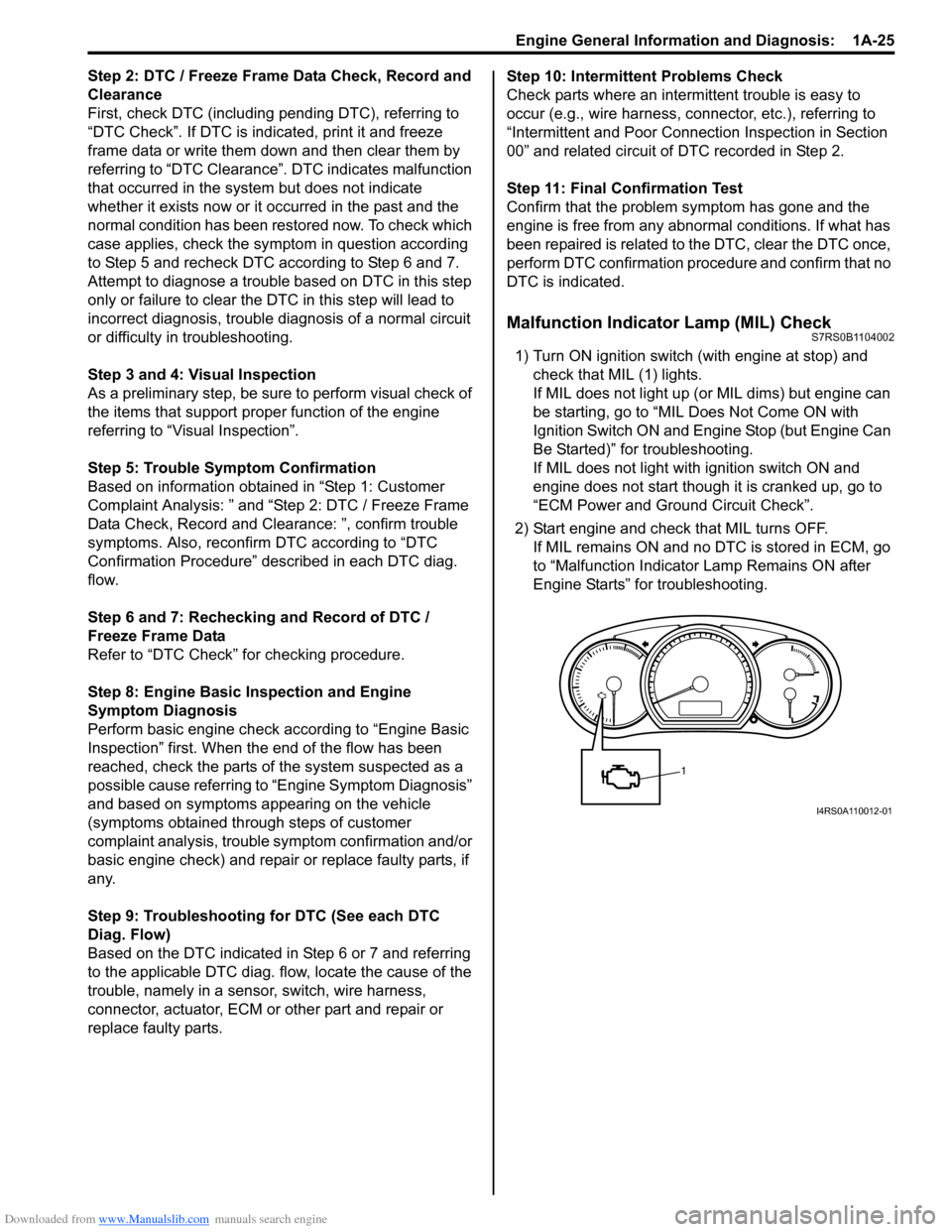
Malfunction Indicator Lamp (MIL) CheckS7RS0B1104002
1) Turn ON ignition switch (with engine at stop) and check that MIL (1) lights.
If MIL does not light up (or MIL dims) but engine can
be starting, go to “MIL Does Not Come ON with
Ignition Switch ON and Engine Stop (but Engine Can
Be Started)” for troubleshooting.
If MIL does not light with ignition switch ON and
engine does not start though it is cranked up, go to
“ECM Power and Ground Circuit Check”.
2) Start engine and check that MIL turns OFF. If MIL remains ON and no DTC is stored in ECM, go
to “Malfunction Indicator Lamp Remains ON after
Engine Starts” for troubleshooting.
1
I4RS0A110012-01
Page 111 of 1496
Downloaded from www.Manualslib.com manuals search engine Engine General Information and Diagnosis: 1A-61
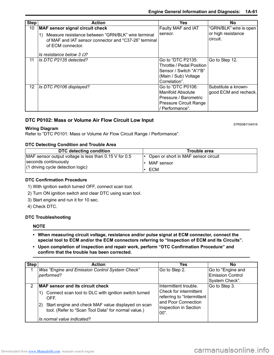
DTC P0102: Mass or Volume Air Flow Circuit Low InputS7RS0B1104018
Wiring Diagram
Refer to “DTC P0101: Mass or Volume Air Flow Circuit Range / Performance”.
DTC Detecting Condition and Trouble Area
DTC Confirmation Procedure1) With ignition switch turned OFF, connect scan tool.
2) Turn ON ignition switch and clear DTC using scan tool.
3) Start engine and run it for 10 sec.
4) Check DTC.
DTC Troubleshooting
NOTE
• When measuring circuit voltage, resistance and/ or pulse signal at ECM connector, connect the
special tool to ECM and/or the ECM connectors re ferring to “Inspection of ECM and Its Circuits”.
• Upon completion of inspection and repair work, perform “DTC Confirmation Procedure” and confirm that the trouble has been corrected.
10 MAF sensor signal circuit check
1) Measure resistance between “GRN/BLK” wire terminal
of MAF and IAT sensor connector and “C37-26” terminal
of ECM connector.
Is resistance below 3
Ω? Faulty MAF and IAT
sensor.
“GRN/BLK” wire is open
or high resistance
circuit.
11 Is DTC P2135 detected? Go to “DTC P2135:
Throttle / Pedal Position
Sensor / Switch “A”/“B”
(Main / Sub) Voltage
Correlation”.Go to Step 12.
12 Is DTC P0106 displayed? Go to “DTC P0106:
Manifold Absolute
Pressure / Barometric
Pressure Circuit Range
/ Performance”.Substitute a known-
good ECM and recheck.
Step
Action YesNo
DTC detecting condition Trouble area
MAF sensor output voltage is less than 0.15 V for 0.5
seconds continuously
(1 driving cycle detection logic) • Open or short in MAF sensor circuit
• MAF sensor
•ECM
Step
Action YesNo
1 Was “Engine and Emission Control System Check”
performed? Go to Step 2.
Go to “Engine and
Emission Control
System Check”.
2 MAF sensor and its circuit check
1) Connect scan tool to DLC with ignition switch turned
OFF.
2) Start engine and check MAF value displayed on scan tool. (Refer to “Scan Tool Data” for normal value.)
Is normal value indicated? Intermittent trouble.
Check for intermittent
referring to “Intermittent
and Poor Connection
Inspection in Section
00”.
Go to Step 3.
Page 113 of 1496
Downloaded from www.Manualslib.com manuals search engine Engine General Information and Diagnosis: 1A-63
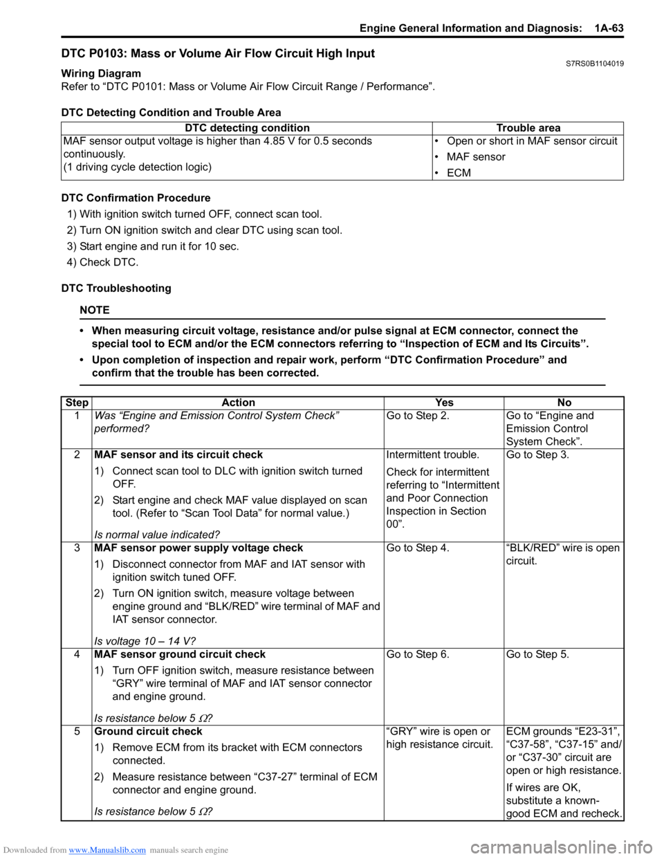
DTC P0103: Mass or Volume Air Flow Circuit High InputS7RS0B1104019
Wiring Diagram
Refer to “DTC P0101: Mass or Volume Air Flow Circuit Range / Performance”.
DTC Detecting Condition and Trouble Area
DTC Confirmation Procedure1) With ignition switch turned OFF, connect scan tool.
2) Turn ON ignition switch and clear DTC using scan tool.
3) Start engine and run it for 10 sec.
4) Check DTC.
DTC Troubleshooting
NOTE
• When measuring circuit voltage, resistance and/ or pulse signal at ECM connector, connect the
special tool to ECM and/or the ECM connectors re ferring to “Inspection of ECM and Its Circuits”.
• Upon completion of inspection and repair work, perform “DTC Confirmation Procedure” and confirm that the trouble has been corrected.
DTC detecting condition Trouble area
MAF sensor output voltage is higher than 4.85 V for 0.5 seconds
continuously.
(1 driving cycle detection logic) • Open or short in MAF sensor circuit
• MAF sensor
•ECM
Step
Action YesNo
1 Was “Engine and Emission Control System Check”
performed? Go to Step 2.
Go to “Engine and
Emission Control
System Check”.
2 MAF sensor and its circuit check
1) Connect scan tool to DLC with ignition switch turned
OFF.
2) Start engine and check MAF value displayed on scan tool. (Refer to “Scan Tool Data” for normal value.)
Is normal value indicated? Intermittent trouble.
Check for intermittent
referring to “Intermittent
and Poor Connection
Inspection in Section
00”.
Go to Step 3.
3 MAF sensor power supply voltage check
1) Disconnect connector from MAF and IAT sensor with
ignition switch tuned OFF.
2) Turn ON ignition switch, measure voltage between engine ground and “BLK/RED” wire terminal of MAF and
IAT sensor connector.
Is voltage 10 – 14 V? Go to Step 4.
“BLK/RED” wire is open
circuit.
4 MAF sensor ground circuit check
1) Turn OFF ignition switch, measure resistance between
“GRY” wire terminal of MAF and IAT sensor connector
and engine ground.
Is resistance below 5
Ω? Go to Step 6. Go to Step 5.
5 Ground circuit check
1) Remove ECM from its br acket with ECM connectors
connected.
2) Measure resistance between “C37-27” terminal of ECM connector and engine ground.
Is resistance below 5
Ω? “GRY” wire is open or
high resistance circuit.
ECM grounds “E23-31”,
“C37-58”, “C37-15” and/
or “C37-30” circuit are
open or high resistance.
If wires are OK,
substitute a known-
good ECM and recheck.
Page 116 of 1496
Downloaded from www.Manualslib.com manuals search engine 1A-66 Engine General Information and Diagnosis:
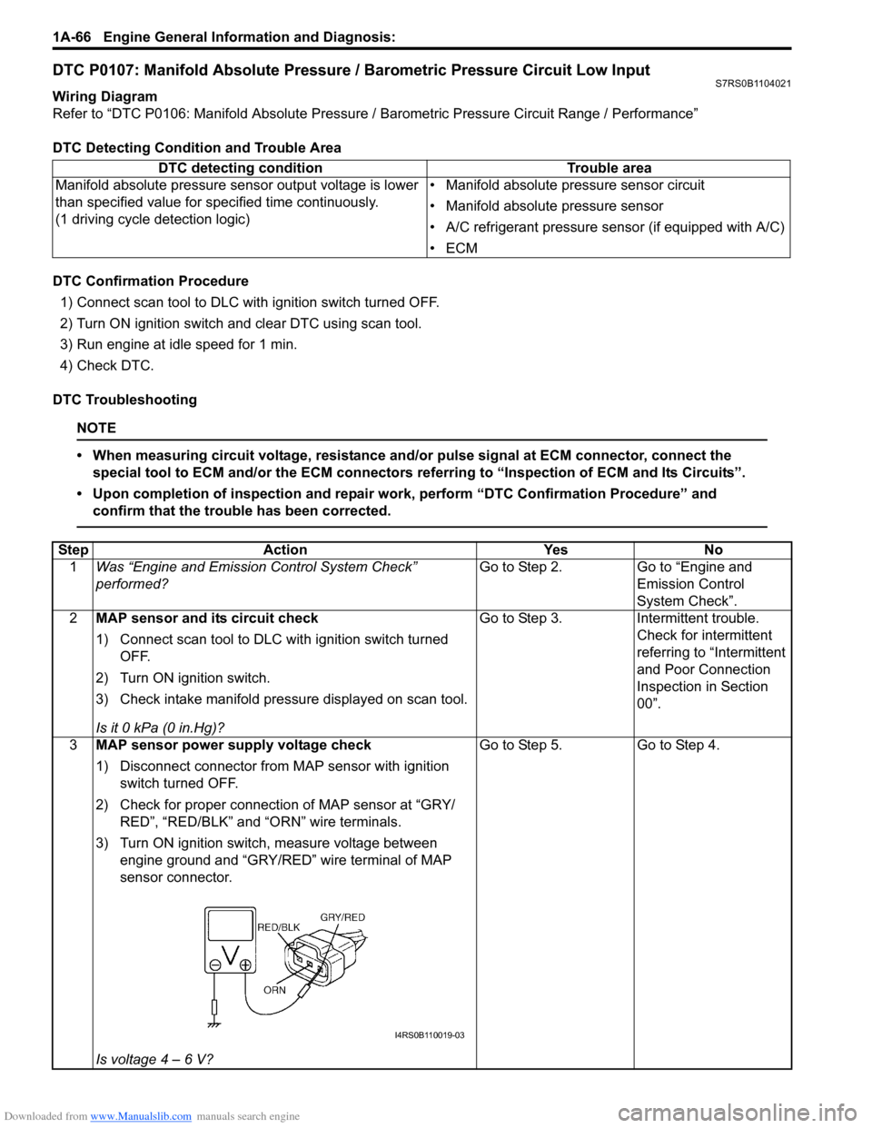
DTC P0107: Manifold Absolute Pressure / Barometric Pressure Circuit Low InputS7RS0B1104021
Wiring Diagram
Refer to “DTC P0106: Manifold Absolute Pressure / Barometric Pressure Circuit Range / Performance”
DTC Detecting Condition and Trouble Area
DTC Confirmation Procedure 1) Connect scan tool to DLC with ignition switch turned OFF.
2) Turn ON ignition switch and clear DTC using scan tool.
3) Run engine at idle speed for 1 min.
4) Check DTC.
DTC Troubleshooting
NOTE
• When measuring circuit voltage, resistance and/ or pulse signal at ECM connector, connect the
special tool to ECM and/or the ECM connectors re ferring to “Inspection of ECM and Its Circuits”.
• Upon completion of inspection and repair work, perform “DTC Confirmation Procedure” and confirm that the trouble has been corrected.
DTC detecting condition Trouble area
Manifold absolute pressure se nsor output voltage is lower
than specified value for s pecified time continuously.
(1 driving cycle detection logic) • Manifold absolute pressure sensor circuit
• Manifold absolute pressure sensor
• A/C refrigerant pressure sensor (if equipped with A/C)
•ECM
Step
Action YesNo
1 Was “Engine and Emission Control System Check”
performed? Go to Step 2.
Go to “Engine and
Emission Control
System Check”.
2 MAP sensor and its circuit check
1) Connect scan tool to DLC with ignition switch turned
OFF.
2) Turn ON ignition switch.
3) Check intake manifold pressure displayed on scan tool.
Is it 0 kPa (0 in.Hg)? Go to Step 3.
Intermittent trouble.
Check for intermittent
referring to “Intermittent
and Poor Connection
Inspection in Section
00”.
3 MAP sensor power supply voltage check
1) Disconnect connector from MAP sensor with ignition
switch turned OFF.
2) Check for proper connection of MAP sensor at “GRY/ RED”, “RED/BLK” and “ORN” wire terminals.
3) Turn ON ignition switch, measure voltage between engine ground and “GRY/RED” wire terminal of MAP
sensor connector.
Is voltage 4 – 6 V? Go to Step 5.
Go to Step 4.
I4RS0B110019-03